38 solenoid valve diagram how to understand
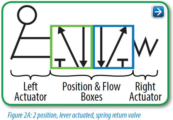
7 Symptoms Of A Bad Shift Solenoid ( & Replacement Cost ) 26/11/2020 · When you replace a shift solenoid, valve body, or solenoid pack, you should always replace the transmission fluid and filter. These are the prices, including parts and labor costs. The prices do not include diagnosis and fluid replacement costs. Single shift solenoid replacement cost: $50 – 150$ Shift solenoid pack replacement cost: $300 – 600$ Valve body … Introduction to Valve Symbol Reading - LunchBox Sessions The operators are little symbols at the left and right sides of the valve symbol, which indicate how the spool is moved. The solenoid operators indicate that the valve can be operated electrically. The envelope that a solenoid operator is attached to is the position that the valve spool will move to when that solenoid is energized.
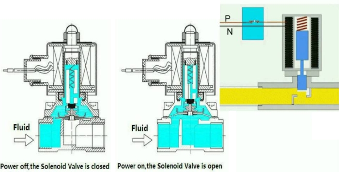
PDF Solenoid Valves and Their Importance in Refrigeration Systems 1 A solenoid is a simple form of an electromagnet consisting of a coil of insulated copper wire. A solenoid valveis an electromechanical valve frequently used to control the flow of liquid or gas. Definitions Solenoid valves are found in many applications and are commonly used in refrigeration and air conditioning systems.

Solenoid valve diagram how to understand
PLC Valve Control Ladder Logic | PLC Valve Logic | PLC ... Consider solenoid valve (SOV) is Normally Close (NC) type. In normal position, the SOV is in off position or de-energized state, so the instrument air supply will be blocked as SOV is Normally closed. if SOV is energized i.e. PLC sends the signal then SOV energizes and becomes normally open (NO), so allows instrument air supply through its. Understanding Circuit Symbols - AutomationDirect Understanding Circuit Symbols. Directional air control valves are the building blocks of pneumatic control. Symbols representing these valves provide a wealth of information about the valve they represent. Symbols show the methods of actuation, the number of positions, the flow paths and the number of ports. Here is a brief breakdown of how to ... PDF ENGINEERING SYMBOLOGY, PRINTS, AND DRAWINGS Module 2 ... ENGINEERING FLUIDS DIAGRAMS AND PRINTS To read and understand engineering fluid diagrams and prints, usually referred to as P&IDs, an individual must be familiar with the basic symbols. EO 1.1 IDENTIFY the symbols used on engineering P&IDs for the following types of valves: a. Globe valve g. Relief valve b. Gate valve h. Rupture disk
Solenoid valve diagram how to understand. How to Read a Spool Valve Schematic Drawing - YouTube C'mon over to where you can learn PLC programming faster and easier than you ever thought possible!===== Chec... Bad transmission solenoid symptoms: Diagnosis and Fixing ... 10/11/2021 · To do this, you need to find a transmission diagram that shows the wiring pattern. Next, you’ll need to look for the pins that go to the faulty solenoid. Remove the transmission plug that’s on the transmission. Then use the scanner to detect the faulty shift solenoid. The trouble codes from the transmission shift solenoid test will help you understand the problem. FAQs: … Bad VVT Solenoid Symptoms: What You Need to Know - In The ... 21/07/2020 · Variable Valve Timing Solenoid Symptoms. These days, since most newer vehicles have variable valve timing, VVT solenoid failure is fairly common. A faulty VVT solenoid can cause several problems. The most common include: Illuminated Check Engine Light. Your car’s primary computer, which is often referred to as the powertrain control module (PCM), monitors … PDF Solenoid Valves - Parker Hannifin solenoid valves and the 180 solenoid pilot control...and all solenoid valves in the field that are equipped with the old style KC-2 coil. When changing from the old KC model coils to the current MKC * E34, B33, E33 and E42 are obsolete. * OE34, OB33, OE33 and OE42 are obsolete. Solenoid Valves Installation and Servicing Instructions SD-15/52021
Concept of Interlocking in PLC - Interlock Ladder Diagram You can understand the “inter-” part of the term when you realize that the code for pump2 would be the same as pump1, except that the pump1 contact would be the interlock instead of pump2 Some programmers (including me) take all the interlock conditions and have them power a … AUDI Fault Codes DTC - Car PDF Manual, Wiring Diagram ... 07/01/2017 · P1577 Open or damaged circuit connected to the solenoid valve of the right hydraulic motor support. The N145 sensor is subject to diagnosis. P1588 Code P158800 reports damage to the power supply line of the solenoid valves of the hydraulic bearings of the power unit. The cause of the problem should be sought in the operation of sensors N144 and ... Solenoid Valves 101- Trimantec To fully understand how these solenoid valves work it's best to start by understanding what a solenoid is. A solenoid is a coil that is tightly wound into a helix. This coil is wrapped around a metallic core which when energized, creates an electromagnet. PDF Simplified Valve Circuit Guide - Omega 8" Nugget solenoid operated valve. This valve does not have provisions for an external pilot supply which is required for "Normally Open" solenoid operated valves. Three-way valve applied to a spring return cylinder. Three-way Valves Three-way valves are the same as 2-way valves with the addition of a third port for exhausting downstream air.
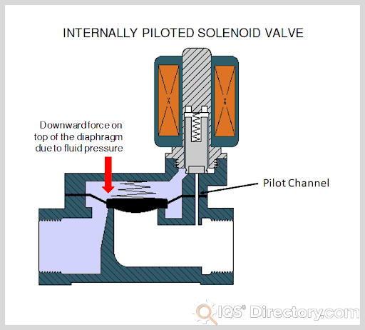
Understanding Solenoid Valves - ACHR News A solenoid valve is an electronically operated device. It is used to control the flow of liquids or gases in a positive, fully-closed or fully-open mode. The valve is commonly used to replace a manual valve or where remote control is desirable. Pneumatic Circuit Symbols Explained - Automationdirect.com ... Mar 21, 2016 — Directional air control valves are the building blocks of pneumatic control. Pneumatic circuit symbols representing these valves provide ... Chevrolet Silverado, GMC Sierra (2007-2013) Fuse Diagram Fuse box diagram (fuse layout), location and assignment of fuses and relays Chevrolet Silverado, GMC Sierra 1500, 2500HD, 3500HD (2007-2013). 3/2 Solenoid Valves Normally Closed Normally open & Universal Solenoid valves operate using electromagnetic attraction to move the valve from the seat and most often, a spring to return the valve to the start position. This direct lift principle works well for small valve sizes or very low pressures but as valve sizes increase, the size of coil and its power consumption rises exponentially making it bulky ...
How a Solenoid Valve Works ~ Learning Instrumentation And ...
Solenoid Driver Circuit Diagram The complete circuit diagram for Solenoid driver circuit is shown in the image below. We will understand why it is designed so, once after taking a look at the complete circuit. As you can see the circuit is very simple and easy to build, hence we can test this using a small breadboard connection.

BOOK 2, CHAPTER 14: Proportional control valves | Power & Motion
How Does 3/2 Way Pneumatic Solenoid Valve Work? The 2-position and 3-port pneumatic solenoid valve can be divided into the normally-closed mode and the normally-open mode. The 3/2-way pneumatic solenoid valve is usually used together with the single-acting pneumatic actuator, and adopts the single electric control, namely the single coil. The coil voltage grade generally adopts DC 12V, DC ...

How to Read a Spool Valve Schematic Drawing - RealPars
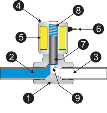
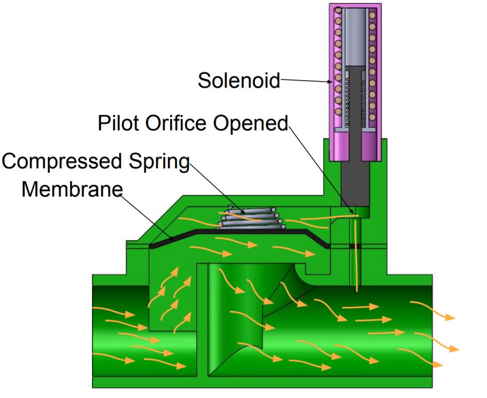
PDF 4 Engineering Information Solenoid Valves A solenoid valve is a combination of two basic functional units: • A solenoid (electromagnet) with its core • A valve body containing one or more orifices Flow through an orifice is shut off or allowed by the movement of the core when the solenoid is energized or de-energized. ASCO valves have a solenoid mounted directly on the valve body. The
Solenoid Valve Symbols
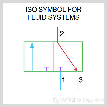
PDF Solenoid and Pressure-operated Valve Technology All leaflets are available on: 42 - General & Engineering Information ISO 1219 symbols - SOLENOID AND PRESSURE-OPERATED VALVE TECHNOLOGY ports/positions function control return symbol (1) 3/2 U (universal) solenoid spring 2 13 NC solenoid air
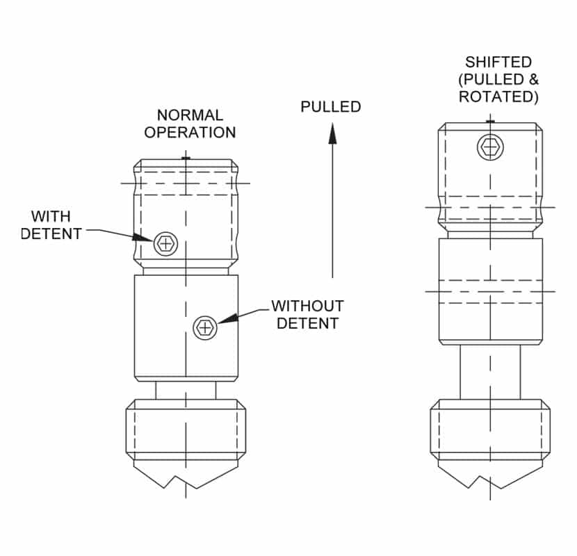
Manual Overrides • Related Fluid Power
PDF Understanding and Troubleshooting Valves ground, and at solenoid on valve in valve box. • Could be a bad solenoid (very rare). • Check to see if the water main is on. (top) These are most of the reasons why a valve is not working properly. If you have the opportunity, take a valve apart and match the parts to the attached diagram. This diagram is for Hardie / Irritrol ®

News
Flow Diagrams | Solenoid Solutions Most equipment requires either a 12V or 24V (volt) DC circuit.Understanding the ANSI symbols and manufacturer's flow diagrams ensures the proper valve is specified. Normally Close (NC) or Normally Open (NO) When designing a direct-acting solenoid valve as part of a fluid control system, the process begins with the flow in a de-energized mode.

How to Read a Spool Valve Schematic Drawing - RealPars
Solenoid Valve - How They Work | Tameson.com It is essential to understand your application before selecting a solenoid valve. Some important selection criteria are as follows: Type of solenoid valve: Determine whether your application requires a 2-way or 3-way solenoid valve. Housing material: Determine valve housing material based on the chemical properties and temperature of the media, but also the environment the …

How Solenoid Valve Works? Parts of Solenoid Valves - Bright ...
Asco Solenoid Valve Wiring Diagram - Wiring Tech Asco solenoid valve wiring diagram free wiring diagram variety of asco solenoid valve wiring diagram a wiring diagram is a streamlined standard pictorial. To engage push type manual operator push stem at base of valve body. On Asco Solenoid Valve 8262 Wiring Diagram. Series and valves are 2-way direct-acting general service below. Asco Solenoid ...
Solenoid Valve Basics
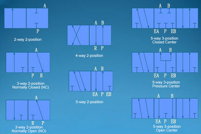
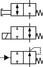
Understanding Pneumatic Schematics - Gears EdS solenoid valve at rest. Triangle Symbols indicate output or exhaust port B In this position Port A Is being exhausted through Arrows indicate exhaust port EA. direction of gas flow through the valve and ports The Dark Rectangles indicate the possible positions or conditions of the valve. This valve has 5 ports and 2 possible

Solenoid Valves | Discrete Control System Elements ...
Smc solenoid Valve Wiring Diagram Gallery - Wiring Diagram ... Wiring Diagram Pictures Detail: Name: smc solenoid valve wiring diagram - SMC type high quality fittings AQ340F 04 00 O D 4mm quick exhaust valve with one touch fittings with silencer in Pneumatic Parts from Home Improvement on
Pneumatic Circuit Symbols Explained |Library.AutomationDirect
how to understand 3/2 and 5/2 solenoid valve pneumatic ... in this video we are describe about pneumatic connection diagram of solenoid valve 3/2 and 5/2 , and practical explanation in this video.pls follow us socia...
Pneumatic Circuit Symbols Explained |Library.AutomationDirect
a guide to understanding pneumatic directional control valves solenoid operated valve. This valve does not have provisions for "Normally Open" solenoid operated valves. N.O. 2-WAY. SYMBOL. ACTUATED. POSITION.
4 Basic Pneumatic Circuits | Power & Motion
How to Read a Spool Valve Schematic Drawing - RealPars The number of ports a valve has is shown by the number of endpoints in a given box. We should only count the ports in a single box once per symbol. For example, in the 3-position valve, there are three boxes that show the three possible positions, but the valve has five physical ports. So the valve will be called a 5/3 solenoid valve.

Solenoid Valves | Discrete Control System Elements ...
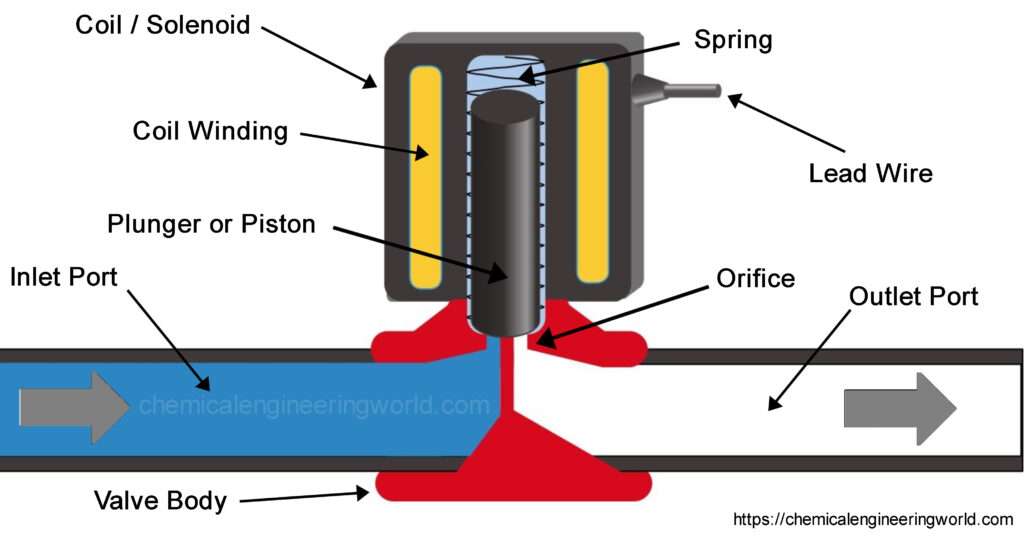
Technical Information - Parker Hannifin Solenoid valves are electrically operated devices used to control flow. They are used for the remote on/off or directional control of liquids, gases and steam. They do not regulate flow. Solenoid valves consist of two main elements: 1.) An electrical coil in the solenoid, and 2.) A valve body or pressure vessel. The solenoid is the electromagnetic

How to Read a Spool Valve Schematic Drawing - RealPars
Solenoid Valve Symbols The solenoid valve symbols are the schematic diagram used to describe functions of the solenoid valve. The schematic diagram is usually applied to the pneumatic system design and product identifications for pneumatic system designers and solenoid valve users to get a thorough understanding of product functions.
Solenoid Valve SYJ Series
How to Read Pneumatic Schematic Symbols.... - Blogger The spring symbol defines the "at rest" position of the solenoid valve. The spring "Pushes" from the side it is drawn on and places the right side block diagram of the valve in function. The T Symbol This symbol indicates that a port is closed and is neither passing or exhausting gas. Pressure or Air supply symbol
Solenoid Valve: What Is It? How It Works, Materials & Uses
Reading Pneumatic Schematic Symbols - Gears EdS solenoid valve. The spring "Pushes" from the side it is drawn on and places the right side block diagram of the valve in function. The Arrows The Arrow symbols illustrate the direction of gasses flowing into and out of the valve ports. Gas is pressure is supplied from port P. De pending on which of the valve blocks is in function, the gas is
What is a Directional Control Valve? (5/2 Solenoid Valve ...
Solenoid Valve Symbols - Solenoid Valves World Solenoid Valve and Common Pneumatic System Symbols. Understanding ANSI / ISO Schematic Symbols for fluid power and pneumatic components are used to identify and graphically denote the function and operation of piped control systems. Understanding schematic symbols will help to better understand at a glance the application, control, direction, amount of flow for actuated valves, cylinders and rotary actuators.
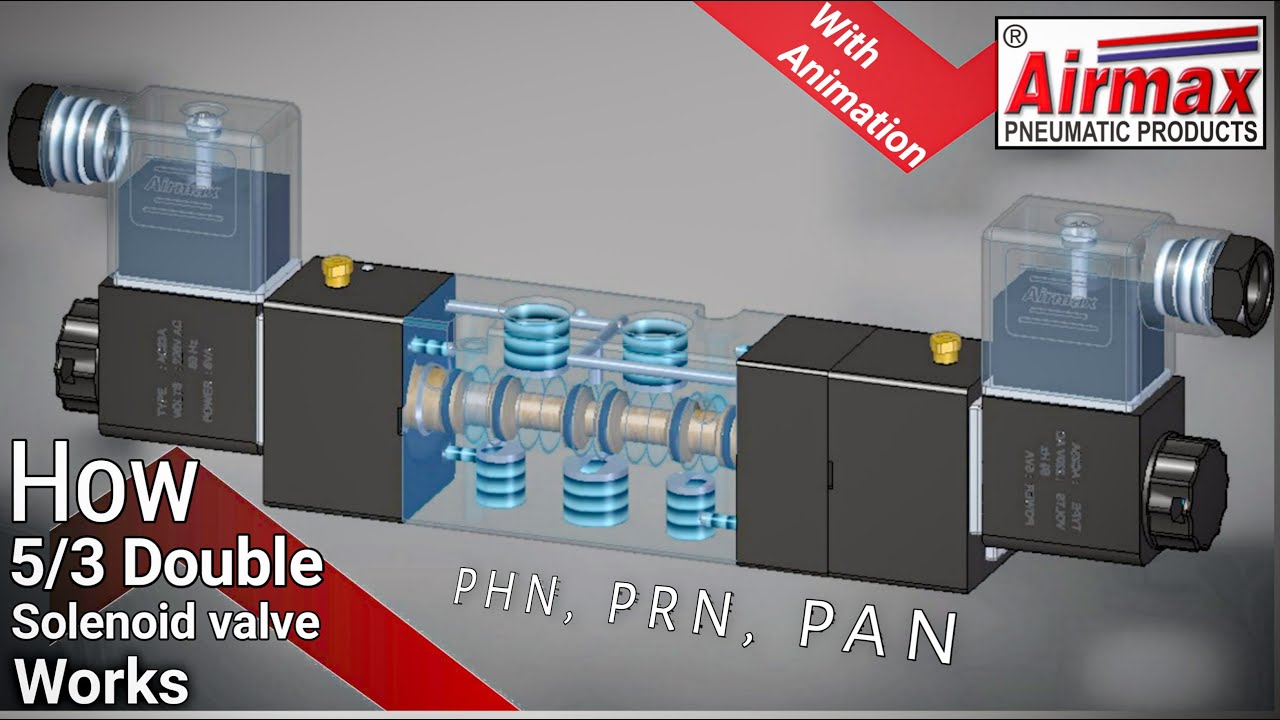
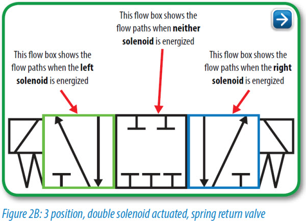
How 5/3 Double Solenoid Valve Works | what is the difference between PHN, PAN & PRN
P0741: Torque Converter Clutch Solenoid Circuit ... 14/06/2021 · To understand this code better, ... Worn valve body; Failed TCC solenoid (when equipped) A problem with the TCC circuit, such as damaged wiring or loose connections (when equipped) A faulty sensor inhibiting TCC lockup (on electrically controlled TCC systems) Low or dirty transmission fluid; Issues with the control module, such as software in need of an update; …

Diagram And Introduction Of Solenoid Valve Symbol Schematic ...
Solenoid Valve Symbols - Connexion Developments The spring symbol defines the “at Rest” position of the solenoid valve. The spring “pushes” from the side it is drawn on and places the right side block diagram of the valve in function. The T Symbol. This symbol indicates that a port is closed and is neither passing or exhausting gas. Pressure of air supply symbol.
Basics: Project 071c 12V solenoid valve at Acoptex.com ...
BMW X5 (E70) (2006-2013) Fuse Diagram - FuseCheck.com Fuse box diagram (fuse layout), location, and assignment of fuses and relays BMW X5 (E70) (2006, 2007, 2008, 2009, 2010, 2011, 2012, 2013).

Understanding Solenoid Design & Function | Tameson.com
PDF solenoid driver circuits - EVDL channel FET, or an IGBT, depending on the voltage and current of the solenoid. The pass transistor applies voltage to the solenoid and the series RC. The circuit turns on the solenoid in the exact same way as Figure 1. The difference is that when this solenoid turns off, the current in the solenoid is routed through two 1N4001 diodes.
Solenoid Valve: What Is It? How It Works, Materials & Uses
PDF ENGINEERING SYMBOLOGY, PRINTS, AND DRAWINGS Module 2 ... ENGINEERING FLUIDS DIAGRAMS AND PRINTS To read and understand engineering fluid diagrams and prints, usually referred to as P&IDs, an individual must be familiar with the basic symbols. EO 1.1 IDENTIFY the symbols used on engineering P&IDs for the following types of valves: a. Globe valve g. Relief valve b. Gate valve h. Rupture disk
How sprinkler solenoid valves work - Make:
Understanding Circuit Symbols - AutomationDirect Understanding Circuit Symbols. Directional air control valves are the building blocks of pneumatic control. Symbols representing these valves provide a wealth of information about the valve they represent. Symbols show the methods of actuation, the number of positions, the flow paths and the number of ports. Here is a brief breakdown of how to ...

Application fundamentals of safety solenoids
PLC Valve Control Ladder Logic | PLC Valve Logic | PLC ... Consider solenoid valve (SOV) is Normally Close (NC) type. In normal position, the SOV is in off position or de-energized state, so the instrument air supply will be blocked as SOV is Normally closed. if SOV is energized i.e. PLC sends the signal then SOV energizes and becomes normally open (NO), so allows instrument air supply through its.
Electric Valve Solenoids (EVS)
What is Solenoid Valve and How does a Solenoid Valve Work?

Solenoid Valve: What Is It? How It Works, Materials & Uses
Solenoid Valve Working and Types - Chemical Engineering World

Direct-Acting Solenoid Valve Animation | Valve, Directions ...

Process Engineering | Solenoid Valve Selection: Don't Be ...
How Solenoid Valves Work - The Engineering Mindset
Directional Valve Symbols

What is a hydraulic diverter valve? How does a diverter valve ...

Solenoid Valve | Hermawan's Blog (Refrigeration and Air ...

Help me to understand pneumatic diagram : r/engineering

What Is A Solenoid Valve? How Does The Solenoid Valve Work ...

How to Read a Spool Valve Schematic Drawing
0 Response to "38 solenoid valve diagram how to understand"
Post a Comment