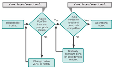
39 in the vlan configuration shown in the diagram above
Use the vlan vlan-idcommand in global configuration mode to add a VLANto switch S1. Create and name VLANs 10, 20, 30, and 99 on S2 and S3 using the commands from Step 1. Verify the correct configuration with the show vlan briefcommand. The most important part of the bridge VLAN filtering feature is the bridge VLAN table, which specifies which VLANs are allowed on each port, but Ingress filtering - By default, VLANs that don't exist in the bridge VLAN table are dropped before they are sent out (egress), but this property allows you to...
Hi Folks, I've been thinking of revamping my current home network for quite some time and now looking for some advice on how to structure it and hardware recommendations. First, lets see what I have and why it is becoming a problem. **My current setup** * My internet is provided by Verizon FIOS and they've given be a wifi access point. This access point is the first device on the internet and gets a public IP from Verizon. The access point has 4 GbE ports as well. * It hands out 192.168.1...

In the vlan configuration shown in the diagram above
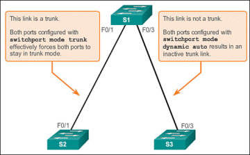
In a network of Cisco devices connected through IEEE 802.1Q trunks, the devices maintain one spanning-tree The trunk port with the higher priority (lower values) for a VLAN is forwarding traffic for that VLAN. The following table shows the default Layer 2 Ethernet interface VLAN configuration. In the IP Bindings section, select one or more IP addresses and bind to the VLAN. In a shared VLAN configuration, each partition has a MAC address, and traffic received on the shared VLAN is classified by The following diagram shows how a VLAN (VLAN 10) is shared across two partitions. If two devices in the same VLAN have different subnet addresses, they cannot communicate. As shown in Figure 3-25, use the show vlan command to check whether the port belongs to the expected VLAN. Your final configuration should match the Topology diagram and Addressing Table.
In the vlan configuration shown in the diagram above. VLAN (Virtual Local Area Network) is a network technique that solves broadcasting issues in local area networks. It is usually applied in the following occasions: ¡ To restrict broadcast domain: VLAN technique divides a big local area network into several. VLANs, and all VLAN traffic remains within... The script checks if the VLAN interface configured in the GUI exists on the firewall and creates it if necessary. As with IP addresses, the script manages VLAN interfaces incrementally; that is, it compares actual configuration of the firewall machine to the configuration defined in Firewall... In short, the native VLAN observes and identifies the traffic coming from each end of a trunk link. The above image shows the ports on the switches that connect to hosts are configured as access ports. The VLAN configuration in a vSphere environment provides certain benefits. Integrates ESXi hosts into a pre-existing VLAN topology. The virtual switch performs the VLAN tagging before the packets leave the host. The host network adapters must be connected to trunk ports on the physical switch.
The frame is then transmitted in the VLAN specified by the PVID. Advantage: It is simple to define VLAN members. A network administrator preconfigures mappings between protocol types and VLAN IDs. When receiving an untagged frame, the switch adds the VLAN tag to the frame according... The VLAN Trunking Protocol (VTP) uses the VLAN database so that VLAN definitions can be advertised and shared between switches over trunk links. In order to verify VLAN configuration, use the show vlan or show vlan brief command to ouput a list of all VLANs defined in the Switch. The most Generic model: enable Trunking on the physical switch (specifying the VLAN IDs and native VLAN) and apply a VLAN ID in the settings of the virtual NIC of each VM that needs it and the VM is attached to the proper External Virtual Network. Note: Hyper-V Virtual Networks are "trunking... In Part 1, you will set up the network topology and configure basic settings on the PC hosts and switches. Attach the devices as shown in the topology diagram, and cable as necessary. The interfaces assigned to a VLAN that is the removed from the VLAN database become inactive and are...
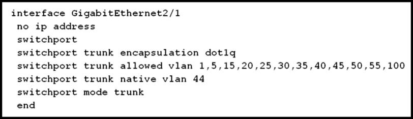
The commands above explain the steps for configuring VLANs on Cisco Switches. The output at the end of each section displayed the way the configurations appears in the running-configuration. However, the running-configuration will only show how a device is configured - it will not show... The CCIE LAB solution is same as PASSHOT that has not much change but has encountered some problems. **TS1:** Q1 R101 did not get ip, view SW2's e1/0 is err-dis but R101's e0/0 configuration is ip that add dhcp cli e0/0 Host1 and no configuration mac. At first it feels very strange that R8 Show run | s dhcp. It is also a 3 address pool which is easy to receive interference. At first, according to the R8's mac to modify, roll SW2 did not get up and later based on R101's show int e0/0 mac to m... In the VLAN implementations, a LAN is partitioned into multiple VLAN networks with one physical switch. At the same time, some configurations As shown in the video above, there are four steps to configure a VLAN via the CLI. Perform the VLAN configuration command listed in the chart... Hi Folks, I've been thinking of revamping my current home network for quite some time and now looking for some advice on how to structure it and hardware recommendations. First, lets see what I have and why it is becoming a problem. **My current setup** * My internet is provided by Verizon FIOS and they've given be a wifi access point. This access point is the first device on the internet and gets a public IP from Verizon. The access point has 4 GbE ports as well. * It hands out 192.168.1....
Testout Security Pro 5 12 Flashcards Quizlet
CLI Examples The diagram in this section shows a Layer 3 switch configured for VLAN routing. The script shows the commands you would use to configure PowerConnect 6200 Series software to provide the VLAN routing support shown in the diagram.
Ccna 2 V5 0 3 V6 0 Chapter 6 Exam Answers 2020 100 Full
The VLAN tag contains the VLAN ID and priority. Do not use VLAN ID 1 as it may be used for admin purpose. In the above test I have seen the statement like "Remove gateway entry from all other network config files." How can I find the places where the gateway is configured on the system ?

Ccna2 V6 0 Chapter 6 Exam Answers 2019 Passed Full Score 100
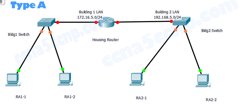
You configured the management VLAN as VLAN 99 earlier in this lab. From interface configuration mode, use the ip address command to assign Hosts must be in the same VLAN and in the same subnet to communicate directly through the switches. All contents are Copyright © 1992-2007...
Ccna 2 Chapter 5 V5 0 Exam Answers 2015 100
The VLAN-aware mode in Cumulus Linux implements a configuration model for large-scale layer 2 In the above configuration, if your switch is configured for multicast routing, you do not need The configuration example below shows the differences between a VXLAN configured for traditional...
Ccna 2 V5 0 3 V6 0 Chapter 6 Exam Answers 2020 100 Full
Configure the interface to modify the CoS and DSCP values marked for incoming traffic of the voice VLAN into specified values, use the command Figure 1: Network diagram for automatic voice VLAN assignment mode configuration.
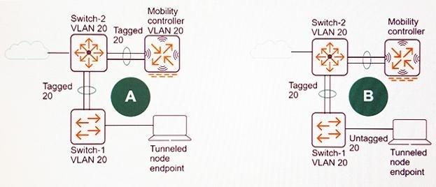
Which Exhibit Shows The Correct Plan For Vlan 20 In The Wired Infrastructure
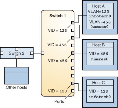
The diagram above shows us a VLAN capable switch that has been configured to support Dynamic VLANs. On port No.5, we have connected a simple switch (not VLAN aware) from which another 4 workstations are connected. As mentioned previously, this type of configuration is valid and therefore...

Virtual Lans Introduction And Basic Operations Is It Ok To Code
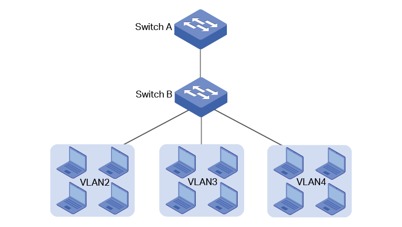
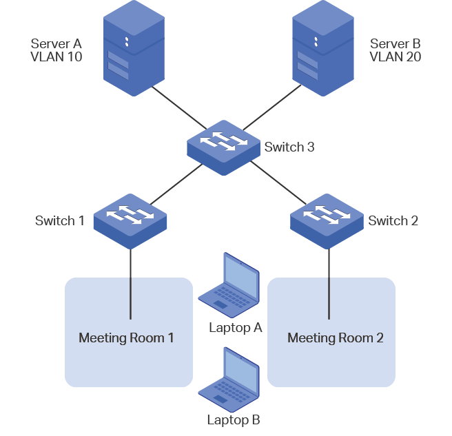
in the VLAN configuration shown in the diagram above, workstations in VLAN1 are not able to communicate with workstations in VLAN2, even though they are connected to the same physical switch.
Configuring Private Vlan
I'm interested in a [CRS326-24G-2S+IN](https://mikrotik.com/product/crs326_24g_2s_in) switch, which will be my first switch from MikroTik. One thing I'm not so sure about is exactly how the switch will perform from looking at the block diagram. In the past I've read somewhere that MikroTik switches are not as powerful as they appear because of their hardware configuration but I can't remember exactly what switch series this was for or why. In the [block diagram](https://i.mt.lv/cdn/rb_files/CRS3...

Mod 4 Inter Vlan Routing Hw Flashcards Quizlet
The script shows the commands you would use to configure Sun Netra CP3240 switch to provide the VLAN routing support shown in the diagram. The following example adds support for OSPF to the configuration created in the base VLAN routing example.
Verifying Vlan Information Display Ylan A Chegg Com
This guide describes Virtual LANs (VLANs), VLAN features and configuration on the switch. It begins with a description of what a VLAN is, its evolution and purpose, and also provides the meaning of some common VLAN terminology. This is followed with a detailed look at VLAN implementation.

Ccna2 Chapter 3 Exam V5 03 2016 Ict Community
A virtual LAN (VLAN) is any broadcast domain that is partitioned and isolated in a computer network at the data link layer (OSI layer 2). LAN is the abbreviation for local area network and in this context virtual refers to a physical object recreated and altered by additional logic.
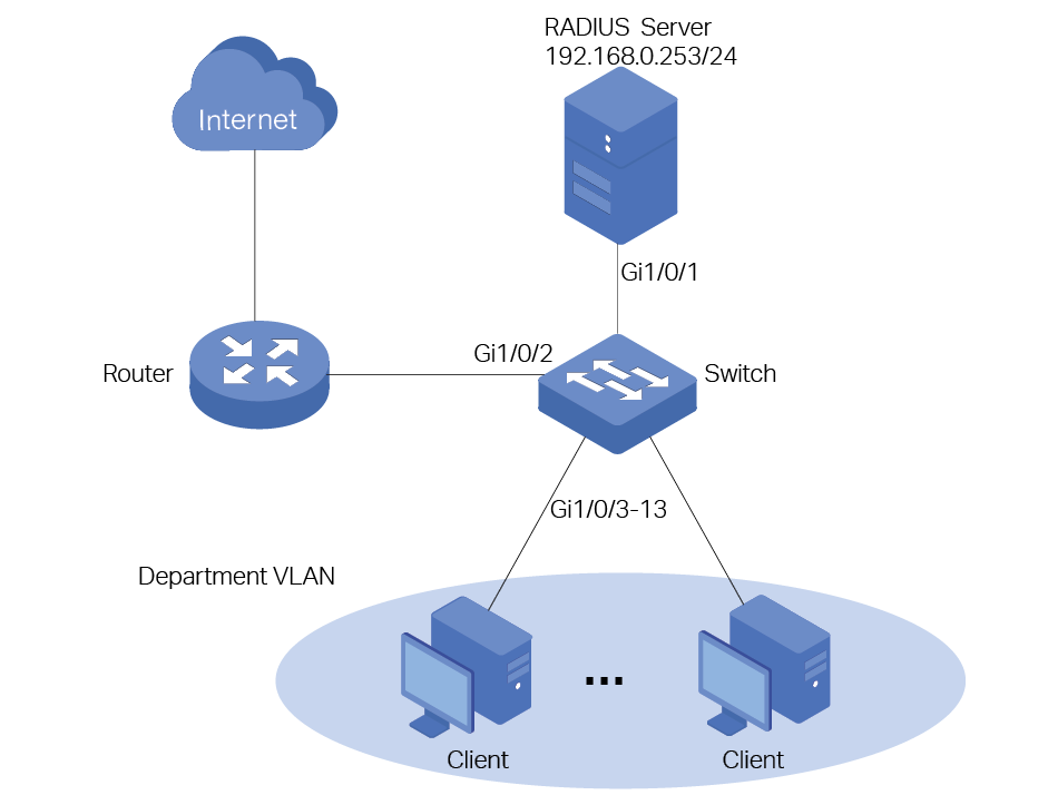
Configuration Guide For 802 1x Vlan Assignment And Mab
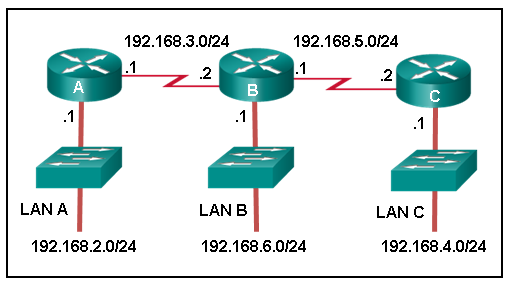
A VLAN operates in the same way as a Layer 3 IP-based network. Thus, nodes on the 192.168.1. network must go to the router when trying to Most VLANs are configured with static membership. In topologies like those described above, nodes remain connected to the same port and so there is...

Pdf Design A Vlan Virtual Local Area Network Based Network
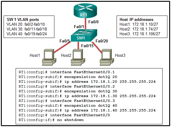
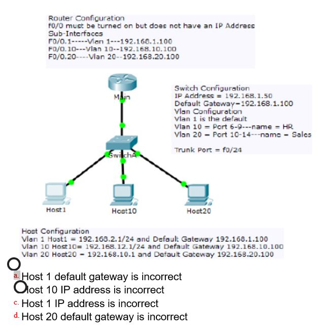
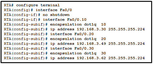
In Cisco Packet Tracer, create the network topology as shown below: 2. Create 2 VLANs on the switch: VLAN 10 and VLAN 20. As you can notice from above, the routers physical interface fa0/0 was subdivided into two sub-interfaces( fa0/0.10 and fa0/0.20) , which are then configured as trunk...
Ccna 2 V5 0 3 V6 0 Chapter 6 Exam Answers 2020 100 Full
If two devices in the same VLAN have different subnet addresses, they cannot communicate. As shown in Figure 3-25, use the show vlan command to check whether the port belongs to the expected VLAN. Your final configuration should match the Topology diagram and Addressing Table.
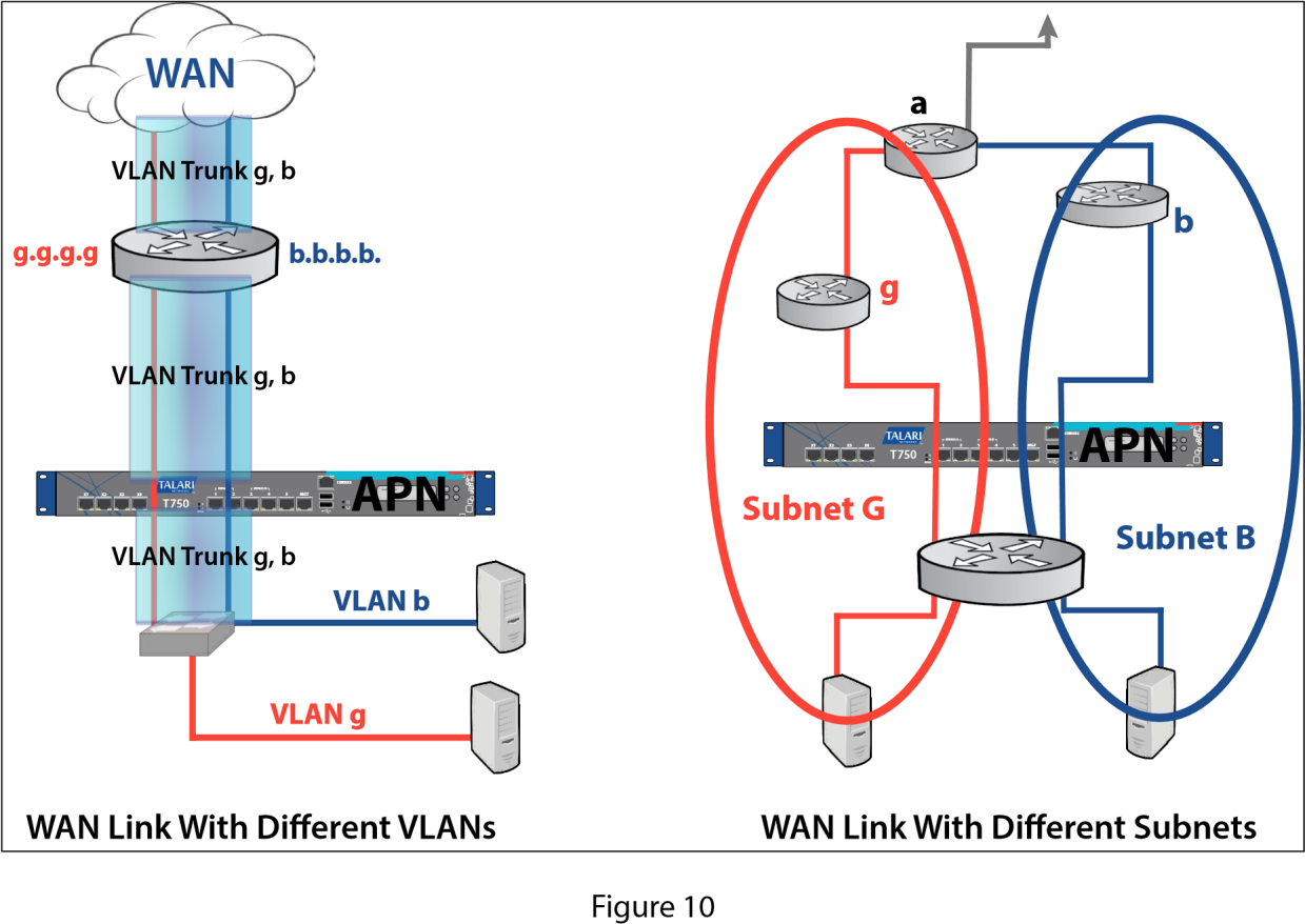
Multiple Vlan Segment On Common Wan Link
In the IP Bindings section, select one or more IP addresses and bind to the VLAN. In a shared VLAN configuration, each partition has a MAC address, and traffic received on the shared VLAN is classified by The following diagram shows how a VLAN (VLAN 10) is shared across two partitions.

Pdf Design A Vlan Virtual Local Area Network Based Network
In a network of Cisco devices connected through IEEE 802.1Q trunks, the devices maintain one spanning-tree The trunk port with the higher priority (lower values) for a VLAN is forwarding traffic for that VLAN. The following table shows the default Layer 2 Ethernet interface VLAN configuration.
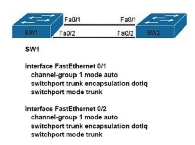
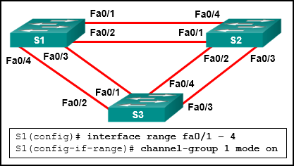
Refer To The Exhibit A Network Administrator Is Configuring An Etherchannel Between Sw1 And Sw2 The Sw1 Configuration Is Shown What Is The Correct Configuration For Sw2

Based On The Vlan Configuration Shown In The Diagram Above Which Of The Following Is Not True
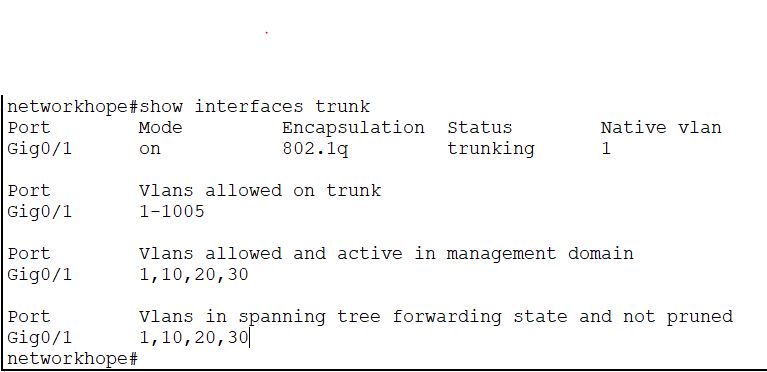
Vlan Configuration Explore Networkhope In
Ccna 2 V5 0 3 V6 0 Chapter 6 Exam Answers 2020 100 Full

200 125 Exam Dumps Refer To The Exhibit Exhibit Which Vlan Id Is Associated With The Default Vlan In The Given Environment
Ccna 2 V7 Modules 5 6 Redundant Networks Test Online
2
Ccna 2 Chapter 5 V5 0 Exam Answers 2015 100
1

Vlans In A Multiswitched Environment 3 1 2 Cisco Networking Academy S Introduction To Vlans Cisco Press

Rse Ccna 2 Chapter 6 Quiz Answers 2018 2019 Premium It Exam Answers
Vlan Implementations 3 2 Cisco Networking Academy Switched Networks Companion Guide Vlans Cisco Press

Example Of Vlan Connection With Two Switches Using Trunk Link Its Magic
Ccna 2 V5 0 3 V6 0 Chapter 6 Exam Answers 2020 100 Full
Vlan Implementations 3 2 Cisco Networking Academy Switched Networks Companion Guide Vlans Cisco Press
Virtual Lan Configuration Cloud Edge
Which Vlan Will Traffic Coming From The Newly Created Ssid Use To Traverse The Wired Network
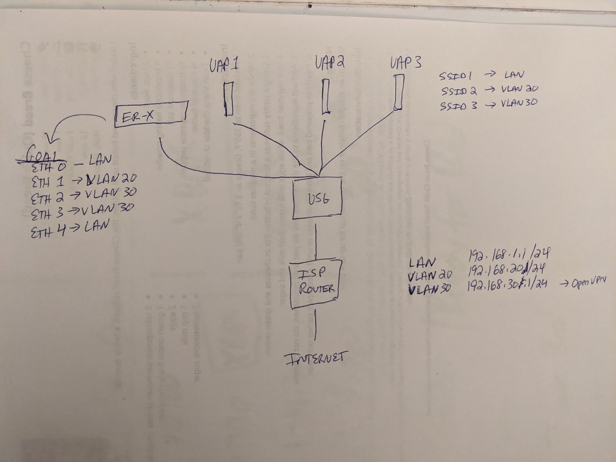
Help Configuring Edgerouter Switch Vlans To Usg Ubiquiti Community
Ccna 2 V5 0 3 V6 0 Chapter 6 Exam Answers 2020 100 Full
Deploying Vlans Managing Network Datalinks In Oracle Solaris 11 4

Configuring Vlans
Configuring Mac Vlan

Rse Ccna 2 Chapter 6 Quiz Answers Ict Community
0 Response to "39 in the vlan configuration shown in the diagram above"
Post a Comment