38 fuel oil piping diagram
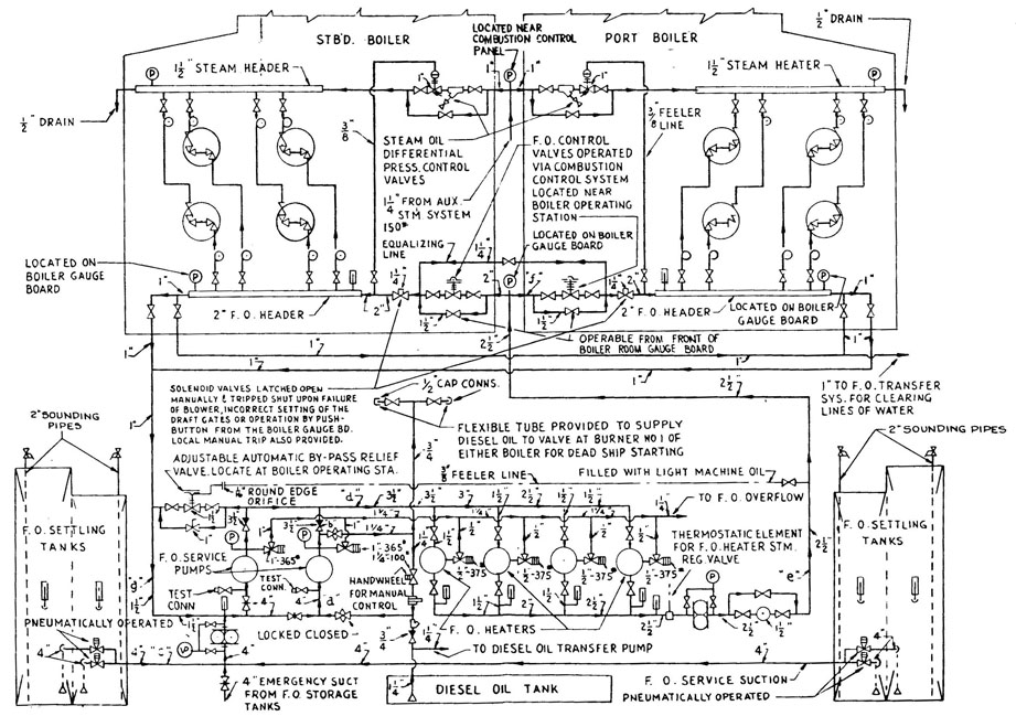
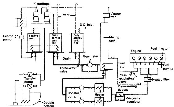
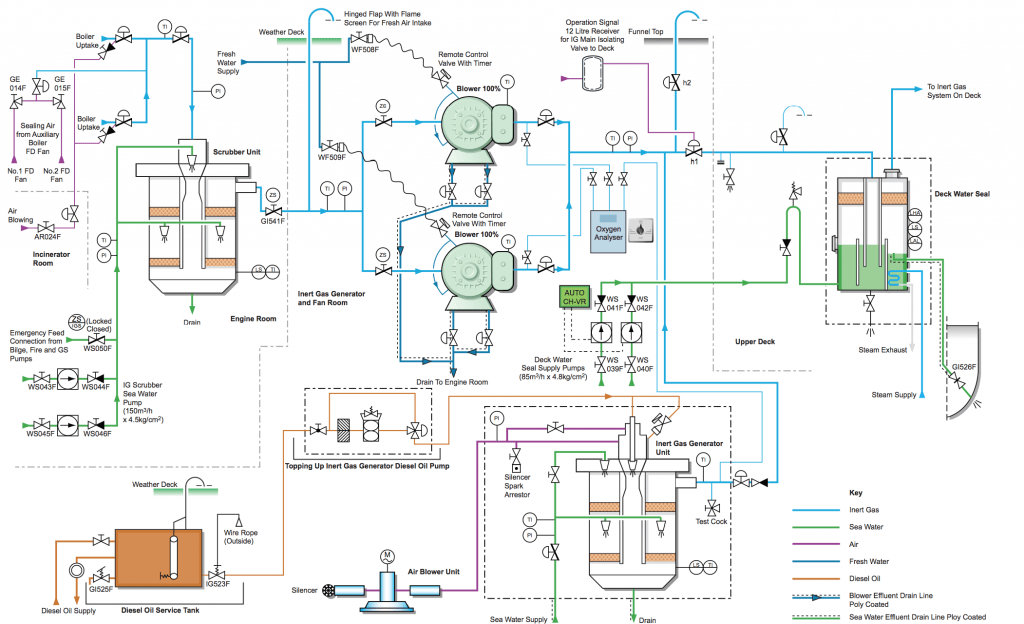
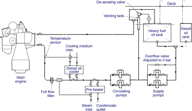
PDF Fuel Oil Piping System Part 1 - General B. Handle fuel oil system components carefully to avoid damage to material component, enclosure and finish. C. Store fuel oil system components in a clean, dry space and protect from the weather. PART 2 - PRODUCTS 2.1 PIPE AND FITTINGS: A. Fuel Oil Piping Buried Below Ground: 1. PDF Fuel Oil System - Uniri In the system shown in the diagram above, the oil is stored in tanks in the double bottom from which it is pumped to a settling tank and heated. After passing through centrifuges the cleaned, heated oil is pumped to a daily service tank. From the daily service tank the oil flows through a three-way valve to a mixing tank.
PDF U.S. Department of Veterans Affairs No.2 Burner Fuel Oil Systems, Burner Fuel Oil Systems - Standard Piping Diagram Author: Department of Veterans Affairs, Office of Construction and Facilities Management, Facilities Standards Service Subject: standard detail Created Date: 8/5/2021 6:34:18 PM
Fuel oil piping diagram
PDF I. Piping Diagrams I. PIPING DIAGRAMS Figure 6 . 23 LP- 276 REV. 3.28.14 Figure 7 NOTES: 1. This drawing is meant to demonstrate system piping concept only. Installer is responsible for all equipment and detailing required by local codes. 2. Boiler circulator(s) must be rated for open loop applications. Do not use cast-iron circulators. PDF PiPing: Double-WalleD SyStemS D - Maine PiPing: Double-WalleD SyStemS D ouble-walled piping systems consist of pipes within pipes and are designed to prevent releases into the environment by containing leaked fuel in the "interstitial space" created between the two walls of the pipe. There are two types of double-walled pipe: Rigid piping made of fiberglass-reinforced plastic (FRP). PDF An Engineering Guide to Modern Fuel Systems that is found in the building. Storage tanks and buried piping will not be addressed. Description of a modern diesel fuel system as a standby energy source. The modern diesel fuel or fuel oil systems are used differently than systems designed a decade or more ago. In early fuel oil system designs, boilers were the primary user of the fuel. The ...
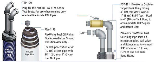
Fuel oil piping diagram. Fuel Oil Piping Diagram for Main Tank… - 3sinfotech Fuel Oil Piping Diagram for Main Tank, Day Tank, and Diesel Genset Fuel oil systems design has always been a challenge for most designers. It involves thorough knowledge of NFPA codes, EPA regulation, local and state laws, and client requirements. 2019 GUIDELINES FOR ON BOARD SAMPLING FOR THE … .5 be clearly marked for easy identification and described in either the piping diagram or other relevant documents; .6 each sampling point should be located in a position shielded from any heated surface or electrical equipment and the shielding device or construction should be sturdy enough to endure leaks, splashes or spray under design pressure of the fuel oil supply line so … Chapter 13: Fuel Oil Piping and Storage, Mechanical Code ... 1301.4 Fuel Tanks, Piping and Valves. The tank, piping and valves for appliances burning oil shall be installed in accordance with the requirements of this chapter. Where an oil burner is served by a tank, any part of which is above the level of the burner inlet connection and where the fuel supply line is taken from the top of the tank, an ... PDF Fuel Oil Piping Systems Installation Instructions OPW FlexWorks Fuel Oil Piping Systems are designed to provide a reliable, secondarily contained, underground fuel supply system to generators and boilers from remote fuel tanks. Typical applications include a 3/4" or 1" supply and a 1" overflow return line running from a remote AST or UST to a generator engine or boiler Day Tank.
DOC Section 231113 - Facility Fuel-oil Piping If fuel-oil piping is installed with less than [12 inches (305 mm)] of cover to finished grade, install in containment piping. Comply with requirements in Section 312000 "Earth Moving" for excavating, trenching, and backfilling. Fuel Oil System for Marine Diesel Engine The fuel oil system for a marine diesel engine can be considered in two parts—the fuel supply and the fuel injection systems. Fuel supply deals with the provision of fuel oil suitable for use by the injection system. Marine Fuel oil system includes various piping systems provided for bunkering, storage, transfer, offloading and treatment of ... PDF FUEL OIL PIPING AND STORAGE - ecodes.biz Thefueloilsystemshallbesized for themaximum capacity of fuel oil required. The minimum size of a supply line shall be3/ 8 -inch (9.5 mm) inside diameter nominal pipe or 3/ 8 -inch (9.5 mm) OD tubing. The minimum size of a return line shall be1/ 4 -inch (6.4 mm) inside diameter nominal pipe or 5/ 16 -inch (7.9 mm) outside diameter tubing. STANDARD DETAILS (PG-18-4) - Office of Construction ... Natural Gas and Liquefied Petroleum Gas Burner and Igniter Fuel Standard Piping Diagram: PDF. SD235239-04: No. 2, 5 & 6 Burner Fuel Oil Systems Standard Piping Diagram : PDF. SD236400-01: Air cooled chiller - piping connections: PDF. SD236400-02: Water cooled chiller - piping connections: PDF. SD236500-01:
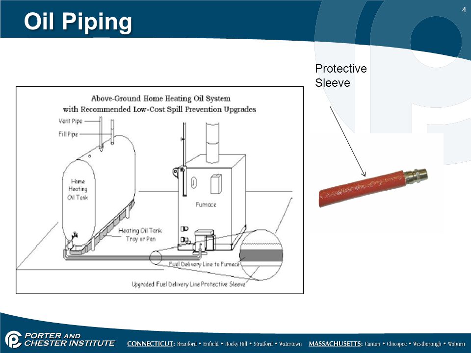
PDF FLOW DIAGRAM OF FUEL OIL SYSTEM (SSF DIESEL ENGINES).Sheet ... fuel oil to diesel is to in pipe specifica71t* oss-e4a a. 2'. n-rj 1/2* n-rj e. cp with a to tx xØØØl set nessi.Æ psig ax ftÆl ort so 1/2- to fl.-el on- ecircu-at1œa 2 oil rev. per oe-6345 ed. c. 11 0.6 retired exe>ptic date cate cate civil elec. oconee a istec rture condition 1 power nuclear station units 1, 2 & 3 flow diagram of fuel ... PDF READY Oil Tanks and Piping Chapter Oil Tanks and Piping Chapter 3 Chapter 3—Oil Tanks and Piping 3-3 Introduction The comfort, cleanliness and efficiency of today's oilheat systems rely on clean, uncontaminated fuel reaching the oilburner. To achieve this: • Install tanks properly. • Maintain tanks by regularly inspecting them and fixing minor defects before PDF FUEL OIL PIPING AND STORAGE - ecodes.biz ground fuel oil tanks. 1305.4 Return piping. Return piping shall connect to the top of the fuel oil tank. Valves shall not be installed on return piping. 1305.5 System pressure. The system shall be designed for the maximum pressure required by the fuel-oil-burning appli-ance. Air or other gases shall not be used to pressurize tanks. 1305.6 Fill ... PDF Sst & Srs Day Tank Manual main fuel tank. The Day Tank must not be more than 18' higher than the lowest fuel level in the main fuel tank. Never locate the Day Tank in a confined space without consideration for accidental fuel spillage and use a rupture basin when necessary. Never locate the Day Tank near a surface or object which may be adversely affected by fuel oil. Never
TSPS Engineering Manual
The nine major steps of designing generator fuel systems Learning objectives. Know the nine key considerations for designing a generator set fuel oil system. Consult authorities having jurisdiction to review the proposed design early in the project. Recall important rules-of-thumb when designing a fuel oil system. Backup generator sets (gensets) are critical to business continuity and life safety.

Is My Oil Tank Safe? - Garthwaite Energy, Inc.
PDF An Introduction to Petroleum Fuel Facilities: Piping Systems pressure of the ANSI/ASME B16.5 piping system flanges at 100 degrees F (38 degrees C), see Table 1. Test hydrant and direct aircraft fueling systems and installation fuel pipelines with fuel that will be used in the pipeline or, at a minimum, a fuel with the same minimum specification flashpoint as the fuel that will be used when the piping is in

Fuel Oil System Diagram on Ship with Diagram Marine Diesel Engine
Liquids - Kinematic Viscosities - Engineering ToolBox Engine & Gear Oil - Recommended Viscosity vs. Outside Temperature - Oil viscosity vs. temperature. Fuel Oil Burners - Pot types, gun types and rotary types fuel burners. Fuel Oil Combustion Values - Combustion values in Btu/gal for fuel oils No.1 to No.6. Fuels - Viscosities vs. Temperature - Fuels oil viscosities vs. temperature.
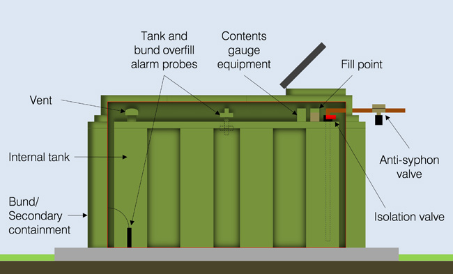
Get to Know Your Oil Storage Tank
Gas & #2 Fuel Oil Supply Design Guide - Aerco GAS & #2 FUEL OIL SUPPLY DESIGN GUIDE . Multi-Fuel, Condensing Boilers • Latest Update: 2/28/2018 . TECHNICAL APPLICATION GUIDE This document provides Fuel Components, Pressure, Piping, and Venting for MFC Series boilers. Applies to MFC Series Models: • MFC 3000 • MFC 4000 • MFC 5000 • MFC 6000 • MFC 8000 MFC 10000 Gas Train

archnav.de - piping diagrams (print)
PDF Drawing, M-017A, Rev. 17, 'Piping & Instrument Diagram ... on piping and instrumentation diagrams those controlled actual termination under db-op-00009 of all other vents or drains are not shown instead, an open ended pipe is displayed, fins untagced pet fuel sampling. the following valves are internal to the fuel manifolds for edg i-i 1-2. diesel dorr 787 158 0034 1 098 i-all doi 01 0039 note 13 t46-1

Ballastwassersysteme | BOLLFILTER
Lube Oil System - an overview | ScienceDirect Topics Lube and seal oil systems, and steam and process gas piping require a thorough cleaning before a new machinery train can be commissioned. Cleaning seal and lube oil systems is also often required during a machinery turnaround. In practice, however, cleaning these systems rarely gets the attention deserved.
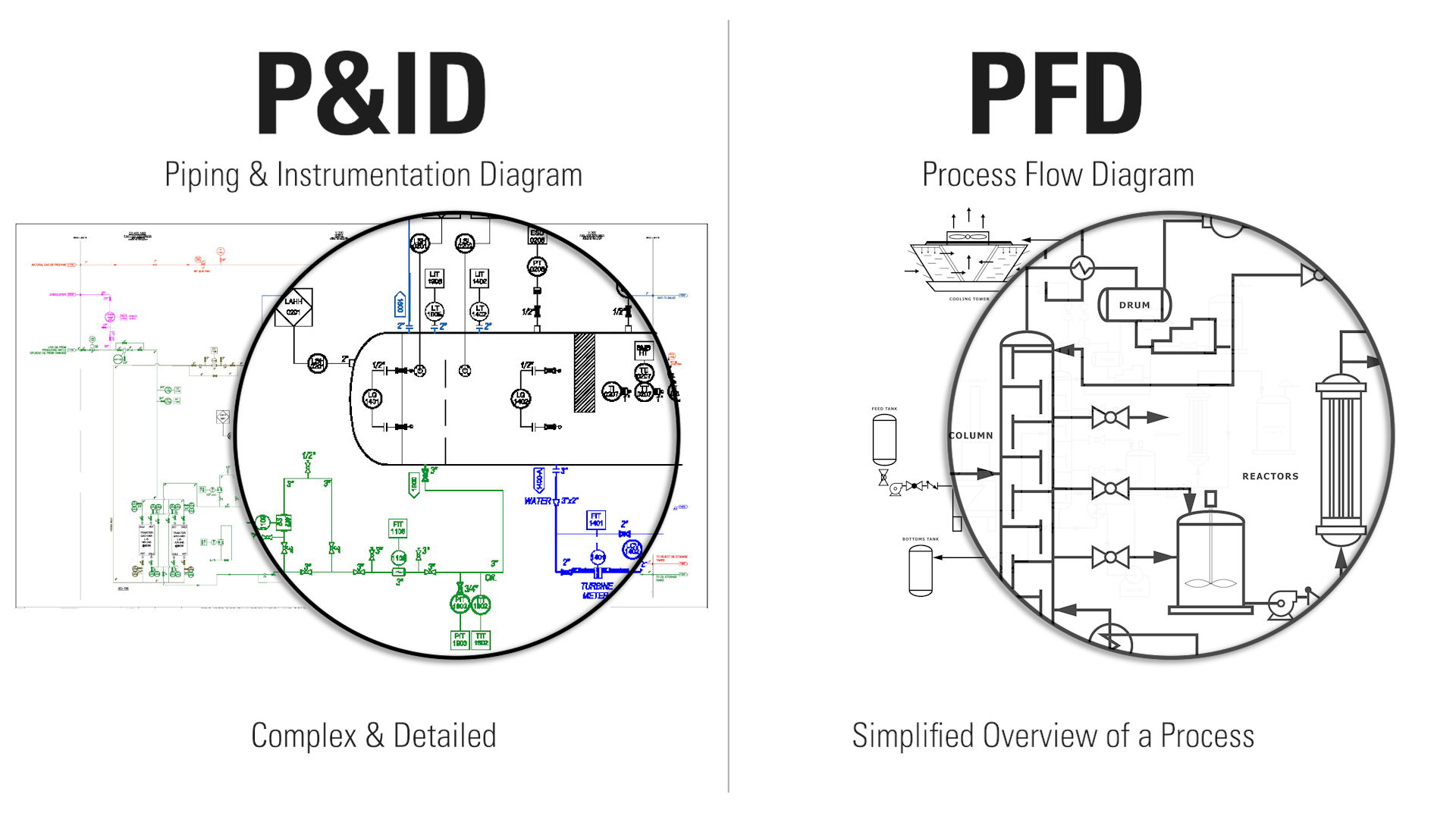
How to Read Oil and Gas P&ID Symbols | Kimray
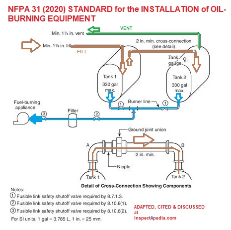
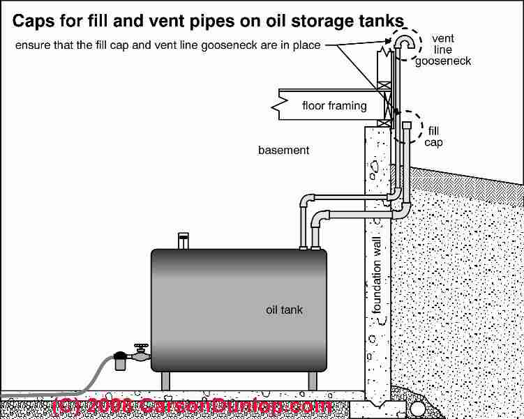
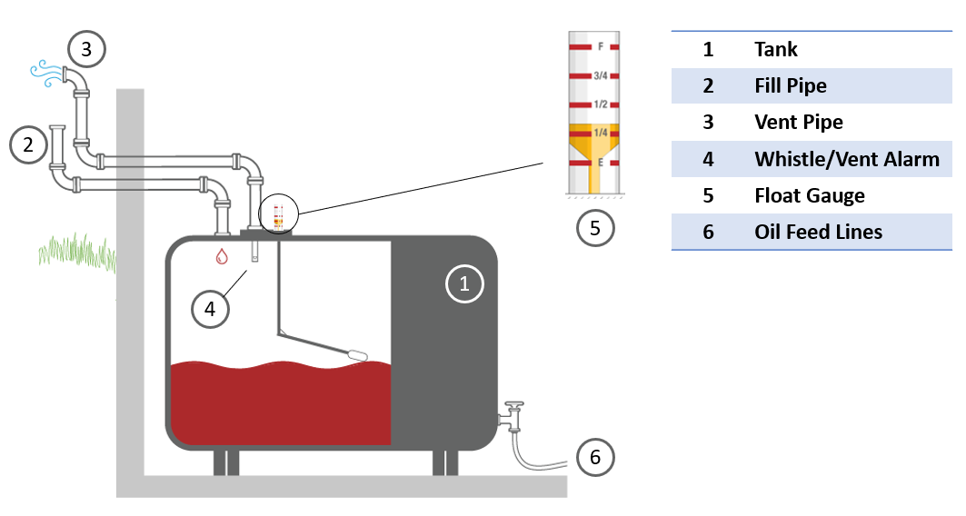
Oil Piping for Duplex or Paired Oil Storage Tanks Oil tank piping: how to hook up fill & vent & oil line piping on duplex or dual oil storage tanks: this document describes the typical piping arrangements for heating oil storage tanks: how the oil tank fill, vent, and supply piping are arranged when two oil storage tanks (or more) are installed at a building.
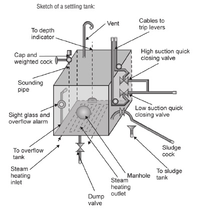
Heating of Fuel Oil Storage Tank - Guideline for Cargo Ships
PDF 06 .1 Rev OIL SUPPLY PIPING - Power Flame burner oil piping can be found in Table 6 this page, Figure 11 on page 12, and Figure 12 on page 13. It is very important to properly size the oil suction line and oil filter, to provide fuel flow to the burner without exceeding 10" suction pressure (vacuum) at the oil pump suction port. The method to properly size copper tubing is outlined

DG & ME FUEL OIL SYSTEM DIAGRAM
PDF Typical Piping for Conventional Single Boiler Installation ... application type diagram see installation manual for complete instructions. install in accordance with all local codes. typical piping for conventional single boiler installation lb-500, lb-750, lb-1000 • safety relief valve setting should not exceed pressure rating of any component in the system. • piping should conform to local codes.

Heating Oil Piping Defects & Leaks: where heating oil leaks ...
MARPOL Annex VI - Fuel Oil Sampling Points. Operators should arrange for in-use fuel oil sampling points to be installed, or designated (in accordance with section 2 of the Annex to MEPC.1/Circ. 864/Rev.1) and ensure the arrangement is described in either a piping diagram or other relevant documents and made available for survey. Early compliance is recommended.
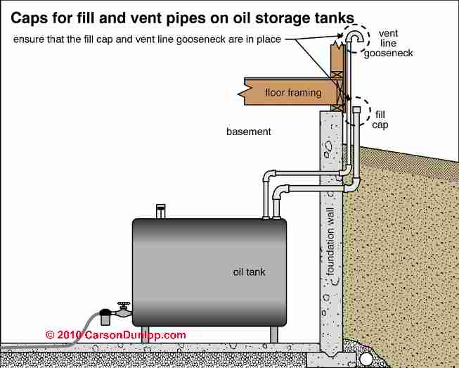
Oil Piping for Duplex or Paired Oil Storage Tanks
PDF Cummins Pt Fuel System This technical manual contains copyrighted material DEPARTMENTS OF THE ARMY AND THE AIR FORCE WASHINGTON 26, DC., 5 September 1966 TM 55-4018-1/TO 88G1-6-21 is published for the use of all concerned.

Fuel Oil Transfer System For Marine Diesel Engines
Pipe & Pump Sizing | Preferred Utilities Mfg To speak to a Preferred engineer who knows NFPA fuel codes and is experienced with fuel oil storage and handling systems, call (203) 743-6741. INSTRUCTIONS The goal is to select a pump that meets the flow and pressure requirements of your project, and design the piping system so that the suction on the pump inlet, and discharge pressure at the ...
Oil Tank Fill & Vent Piping Installation & Inspection
Oil Tank Fill & Vent Piping Installation & Inspection Fill and Product Piping Connections to Domestic Storage Tanks: The fill pipe material shall be 2 in (50 mm) schedule 40 black steel. Threaded joints in the fill piping shall be made fuel oil-tight using joint compound conforming to CAN/ULC-S642-M, Compounds and Tapes for Threaded Pipe Joints, or equivalent.
Project Guide – Marine Four-stroke diesel engine compliant ...
PDF NFPA 31 Fuel Oil Piping, Installation and Testing Chapter ... 8.4 Fuel Return Piping. A return line from a burner or pump to a supply tank shall have no valves or obstructions and shall enter the top of the same tank. 8.5 Supply Piping to Oil-Burning Appliances. 8.5.1 All piping shall be connected into the top of the supply tank. Where two tanks are cross-
Fuel Oil System for Marine Diesel Engine
PDF An Engineering Guide to Modern Fuel Systems that is found in the building. Storage tanks and buried piping will not be addressed. Description of a modern diesel fuel system as a standby energy source. The modern diesel fuel or fuel oil systems are used differently than systems designed a decade or more ago. In early fuel oil system designs, boilers were the primary user of the fuel. The ...
Boiler Efficiency and Combustion Control
PDF PiPing: Double-WalleD SyStemS D - Maine PiPing: Double-WalleD SyStemS D ouble-walled piping systems consist of pipes within pipes and are designed to prevent releases into the environment by containing leaked fuel in the "interstitial space" created between the two walls of the pipe. There are two types of double-walled pipe: Rigid piping made of fiberglass-reinforced plastic (FRP).
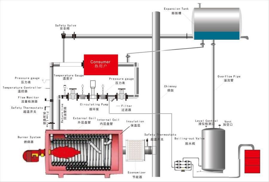
China Customized Electricity Heating Hot Oil System ...
PDF I. Piping Diagrams I. PIPING DIAGRAMS Figure 6 . 23 LP- 276 REV. 3.28.14 Figure 7 NOTES: 1. This drawing is meant to demonstrate system piping concept only. Installer is responsible for all equipment and detailing required by local codes. 2. Boiler circulator(s) must be rated for open loop applications. Do not use cast-iron circulators.

BOILER FUEL OIL SYSTEM

Get Answer) - Light and medium fuel oils, numbers 1, 2, 3 ...
Heating Oil Piping Defects & Leaks: where heating oil leaks ...
Mechanical for Oil Heat - ppt video online download
SUPERVISE FUEL-OIL PIPING AND STORAGE IN BUILDINGS

Fuel Oil System Diagram on Ship with Diagram Marine Diesel Engine
How to Draw and Read Line Diagrams Onboard Ships?

Dual-Fuel Engines | DAIHATSU DIESEL
American engineer . oils. Hand pumps are also used in the ...

Vector Art — Nina Constable

Gas oil station vector stock vector. Illustration of ...
Fuel Injection System Components

Distillation | Distillation, Piping and instrumentation ...

TYPICAL UNDERGROUND FUEL OIL TANK

Heating oil - Wikipedia

Preventing Water From Entering The Fuel System | Beckett Corp.
Flexible Piping Systems for Fuel Oil and Generator ...
Fuel oil System
Submarine Main Propulsion Diesels - Chapter 5

Investigating Fuel Oil Leaks and Spills – Expert Article ...
How an Oil Tank Works - Smart Oil Gauge
0 Response to "38 fuel oil piping diagram"
Post a Comment