35 locknetics maglock wiring diagram
Wiring for the electromagnet must enter the top of the unit through the wire access hole drilled in the frame header (see template). Be certain provisions can be made to bring the wire through the header into the top of the unit. Frame conditions may require the use of filler plates and/or angle brackets. These items are available from Locknetics. Read Mounting Instructions and review this manual. 2. V. Mount the lock in accordance with the Mounting Instructions. DWG T ...
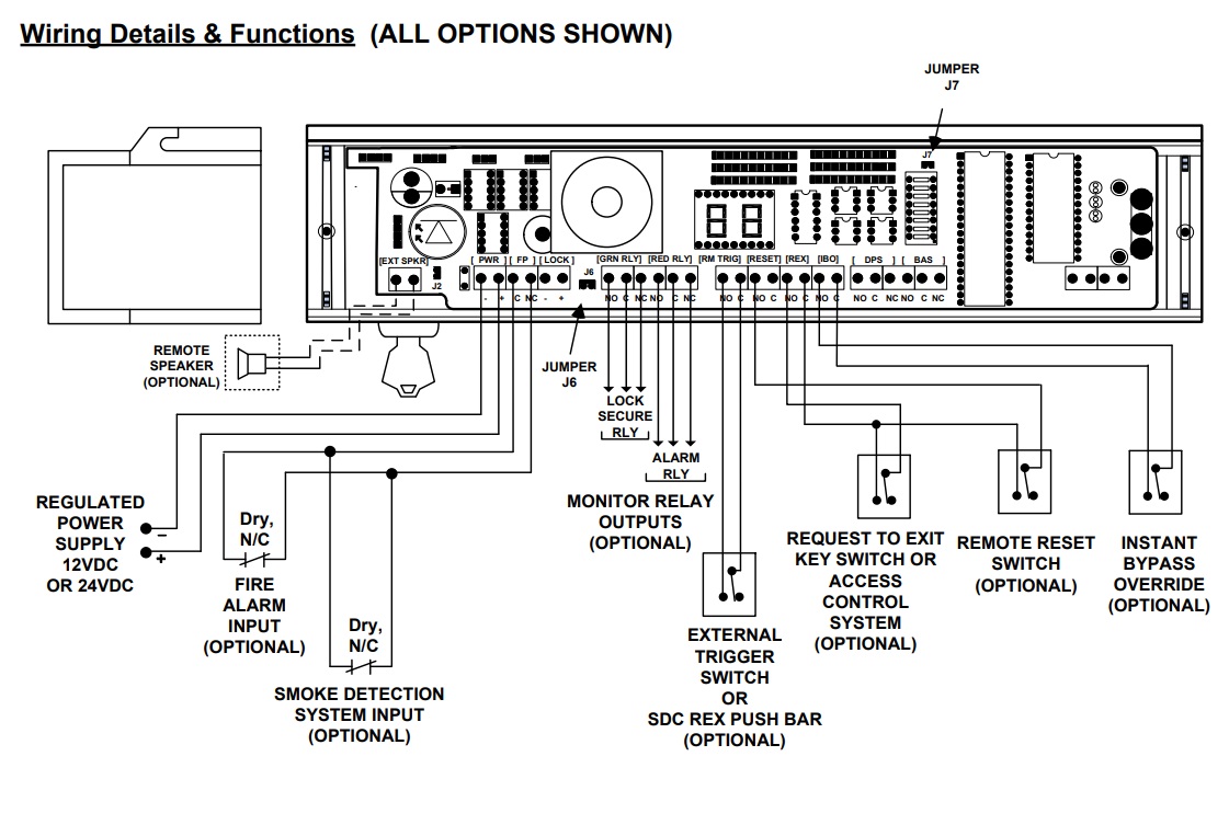
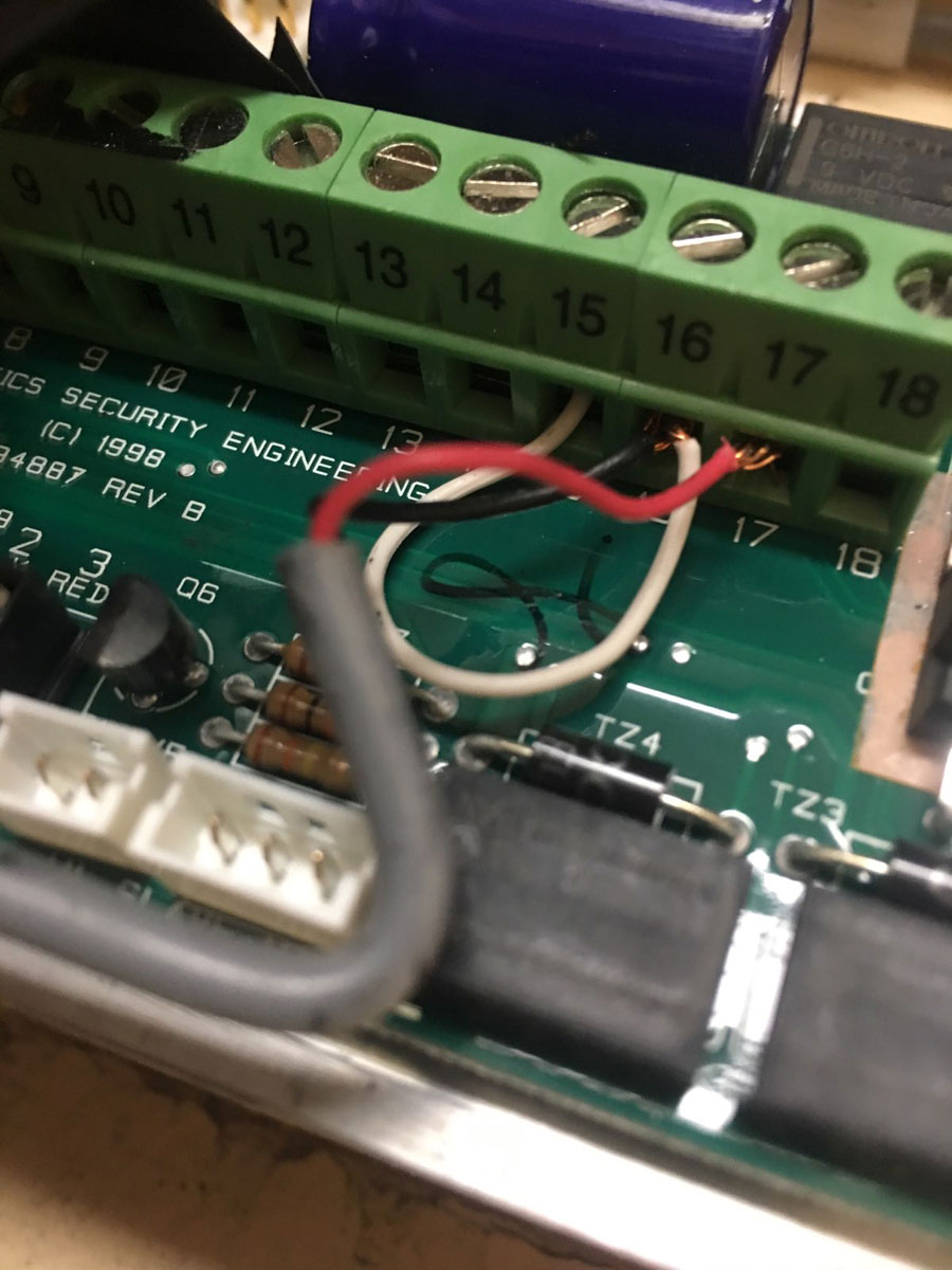
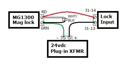
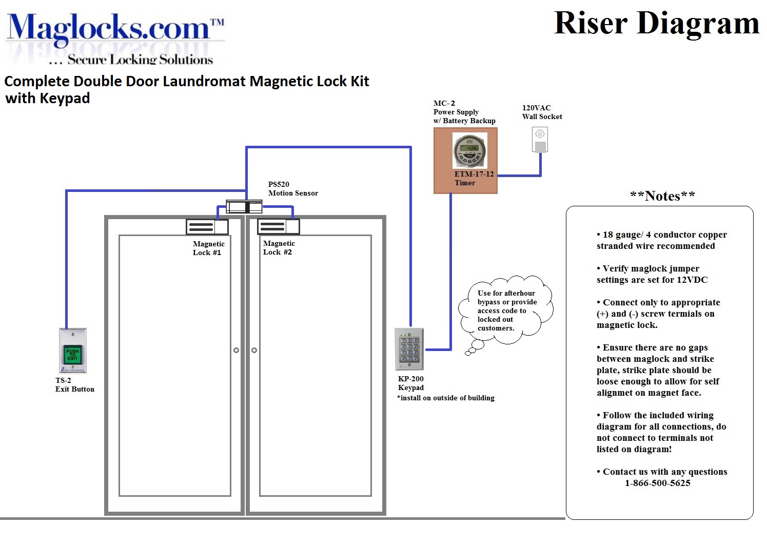
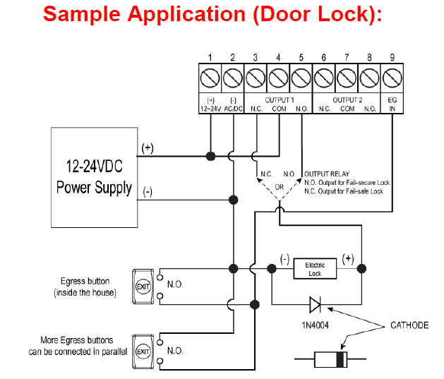
locknetics maglock wiring diagram - What is a Wiring Diagram? A wiring diagram is an easy visual representation with the physical connections and physical layout of the electrical system or circuit. It shows how a electrical wires are interconnected which enable it to also show where fixtures and components might be connected to the system.
Locknetics maglock wiring diagram
Electrical Instructions: ... Do not install a diode in parallel with any magnetic lock. A diode ... Retrofits Discontinued Locknetics 350+.3 pages mag lock wiring diagrams . chexit wiring diagram . lever locks for fire doors . emergency release tool . two single doors with panic bars . two single doors with panic bars . push button release electric strike . HOT ELECTRIC TRIM . is there an rga form? ... 17.09.2018 17.09.2018 1 Comments on Locknetics Maglock Wiring Diagram. Locknetics offers many sizes of each. Herculite door brack- connections (see wiring instructions on next page). Install circuit board(s) (if OUTSWINGING MAGNETIC LOCK with AVS SEE DIAGRAMS ABOVE. PC BOARD.
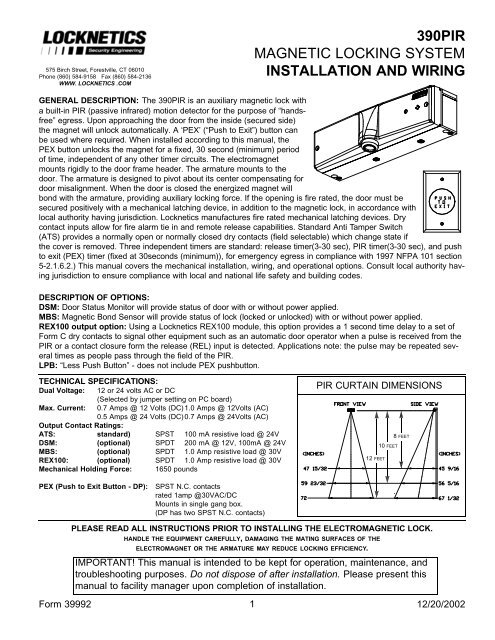
Locknetics maglock wiring diagram. 1 SPDT voltage output . The SDC ACM-1 Access Control Module is an magnetic lock or electric strike. . (for two door or tamdem applications). The next step is to have a 'fail safe' method of cutting the power to the lock to ensure the Where access control equipment is fitted to a fire escape door which includes an Wiring Break glass units and fire alarm interfaces The FIB provides a switching ... WIRING AND TECHNICAL INFORMATION Form 39873 2 10/13/2003 MBS: (Magnetic Bond Sensor - indicates lock status, shown unlocked: changes state when a good magnetic bond is indicated) WHITE: C. WHITE: N.O. (RATING:0.250A@30VDC) NOTE: POLARITY IN THIS CASE DOES NOT MATTER. IT IS SHOWN AS A SUG-GESTION TO KEEP WIRING WITHIN A SYSTEM CONSISTENT. MBS ... 20 Dec 2002 — GENERAL DESCRIPTION: The 390PIR is an auxiliary magnetic lock with ... Locknetics manufactures fire rated mechanical latching devices. Dry.8 pages Schlage M490DEP Delayed egress Electromagnetic Single Lock - 1500 Lb.Hold - Automatic Voltage Selection With MBS & DPS. The M490DE has a 15-second delayed egress timer with audible alarm which can be configured to trigger by an internal "plunger switch," or by external contacts, such as a request-to-exit push bar.
M400 Series Electromagnetic Lock. The M400 Series offers 16 models that are designed to make quick, light work of installation with a bayonet mounting bracket and slide-together components for easy in-field handing and wiring. Locknetics delayed egress maglock manual January 23, 2018 Download >> Download Blocknetics 25S9 Manual Read Online >> Read Online Locknetics 25S9 Locknetics Manual Locknetics Website 390 Locknet Manual 350+ Locknet Wiring Maglock Locknetic Manual 101+ Locknice Manual Maglock Auxiliary Lock Diagram 25S9 Locknetics 25S9, Homebrew Computers, NEC Programming manufacturer's installation and operation instructions, the Life. Safety Code, ANSI/NFPA 70 and 101, and the local authority having jurisdiction.4 pages 1200 lbs. holding force maglock with field selectable dual voltage. Recommended for interior and perimeter security doors. Model VM1290 is a direct retrofit for Locknetics 390+ maglocks and includes a specialized mounting plate that utilizes existing mounting holes. Specifications. 1200 lbs holding force; Magnet size: 10-1/2" L x 2-7/8" H x 1-1 ...
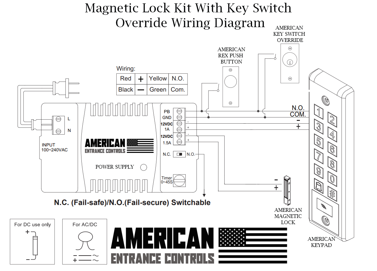
Locknetics Maglock Wiring Diagram This manual covers the complete installation and wiring instructions for the following. GF . Make final wiring connections (see Wiring Diagram: on page LOCKNETICS. M I MN MORTISED MAGNETIC LOCK. INSTALLATION AND WIRING INSTRUCTIONS. Birch Street, Forestville, CT. Wiring should be protected by conduit. 6. Continue to fasten mounting plate to heading using remaining screws. Then, reassemble maglock assembly to mounting plate. 7. Route the enclosed wiring harness through the rectangular hole in the mounting plate. Make the electrical connection as shown below. 8. Make sure that armature/strike plate can be shaken slightly. How to wire a magnetic lock with, backup battery, exit button and key switch. This and other diagram and tutorials are available on our website at; www.there... 8 Connect wiring to board (plus model). 8a Review wiring connections. TB1 TB2 TB3 RED Note: Two MBS plugs are interchangeable. RTD Adjuster Min. Time Max. Time From MBS From MBS From LED From Magnet Polarized Black/Red NO NC C NO NC C DC(+) DC(-) DC Power DPS: 0.25A, 30VDC, Resistive Contacts shown in open-door state MBS: 1A, 30VDC, Resistive
MAGLOCK FACP Operation: 1. Outputs 1 and 2 have FACP override and will completely lose power when FACP ... Blank Wiring Diagram : 7: 4 : Wire run lengths • Use the following table to estimate the gauge of wire required for the application. • Wire length based on 15% voltage drop at 12 or 24V using stranded copper wire. • The wire gauge ...
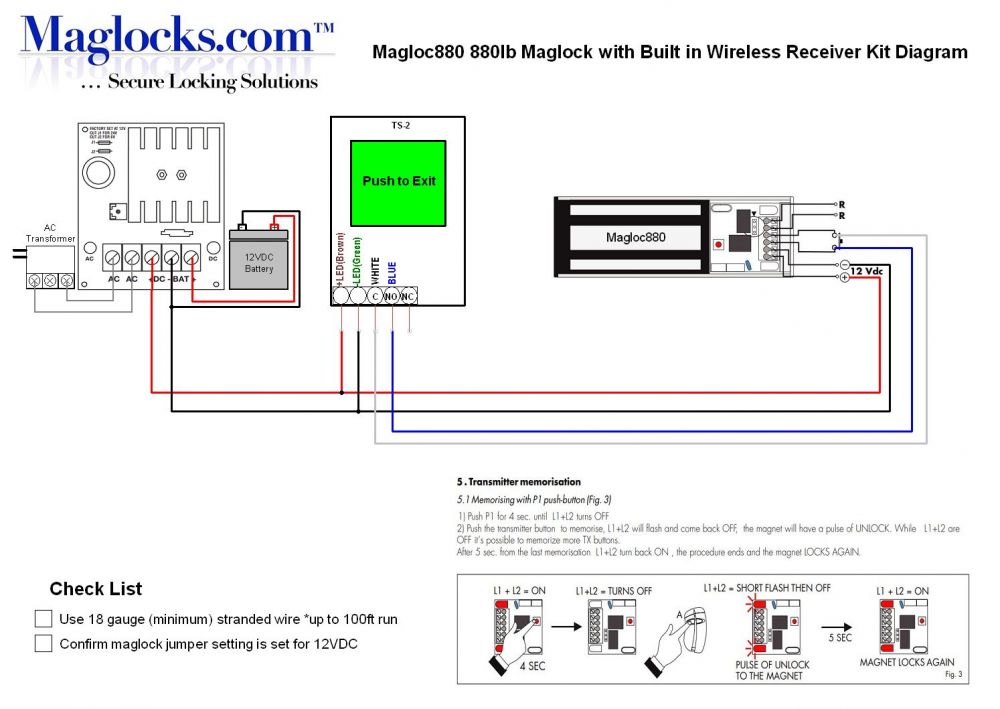
- WIRING INSTRUCTIONS— Magnetic lock or fail safe strike with button, keypad, maintained button and remote receiver. wired in series Power Supply for fail safe strikes and magnetic locks should be DC. If this is not available you may use an AC power source and wire inline a "Full Wave Bridge" rectifier. This will conver t the AC to DC.
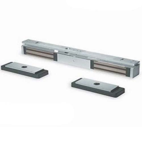
Locknetics provides the most complete selection of electromagnetic locks in the industry. The GF3000 Series Shear Lock features a patented design offering advances over any Shear Lock on the market. Unique mounting features provide a "floating" action of both the lock assembly and the armature. This design
Discover the Simplicity of Locknetics Backed by the strength and promise of Allegion, Locknetics provides electromechanical hardware for access control solutions. Designed to fit the challenges of everyday, on the job applications, the Locknetics portfolio, with electric strikes, electro-magnetic locks and access control accessories, offers ...
Locknetics Maglock Wiring Diagram - Securing Storefronts With Electromagnetic Locks Locksmith Ledger / Wires and circuits are the base of your electrical system. Learn about different types of wiring, cords, switches, and outlets...
Dorma Ed 100 Wiring Diagram; Locknetics Maglock Wiring Diagram; Wiring Diagram For Old Dayton 120 Volt Motor 5k547 1/4 Hp; Paragon Defrost Timer 8141 00 Wiring; Crux Socgm 17 Wiring Interface; Pioneer Deh X3600ui Wiring Diagram; B-4300-209 Wiring Diagram; Vt750c2 Wiring Diagram; Matek F405 Ctr Wiring Diagram; Exmark Metro 48 Parts Diagram ...
LOCKNETICS 575 Birch Street, Forestville, CT 06010 Phone (860) 5840158 Fax (860) 584-2136 Www.locknetics.com 268M / 268MN MORTISED MAGNETIC LOCK INSTALLATION AND WIRING INSTRUCTIONS The 268M series electromagnetic powerlock is a custom engineered electromagnetic lock designed to be mortise mounted into both the door frame and the door.
April 17th, 2019 - The following is a diagram showing how a Maglock magnetic lock can be easily wired to a video door entry system - in this case using the AccessVu system Maglock Z bracket fixing options Depending on which way the door opens will depend on how to install the maglock magnetic lock - and also whether you need a Z bracket or not
17.09.2018 17.09.2018 1 Comments on Locknetics Maglock Wiring Diagram. Locknetics offers many sizes of each. Herculite door brack- connections (see wiring instructions on next page). Install circuit board(s) (if OUTSWINGING MAGNETIC LOCK with AVS SEE DIAGRAMS ABOVE. PC BOARD.
mag lock wiring diagrams . chexit wiring diagram . lever locks for fire doors . emergency release tool . two single doors with panic bars . two single doors with panic bars . push button release electric strike . HOT ELECTRIC TRIM . is there an rga form? ...
Electrical Instructions: ... Do not install a diode in parallel with any magnetic lock. A diode ... Retrofits Discontinued Locknetics 350+.3 pages










0 Response to "35 locknetics maglock wiring diagram"
Post a Comment