37 dc motor wiring diagram 4 wire
I'm a mechanical engineer but I've had a few electrical topics scattered throughout my course (up to and including 3-phase motors and transformers and phasor calculations for reactive power). Thing is, we never really studied power electronics. I want to understand how a real-world pure sine wave inverter works (the kind that converts 12V DC to 230V 50Hz AC). Not planning to build anything, just for the sake of curiosity. I understand the basic principle of chopping the 12V at high frequency to... **My Background...** I've been working on the C-5 for about 5.5 years as a flight line Crew Chief and flying Crew Chief. Crew Chief at my base basically just change tire, windows, take off panels, and do inspections. I don't work on cars so my only experience with maintenance is working on planes. I don't plan to use this certification until I retire from the military after 20 years. I spent a lot of time looking for reviews, so I want to give that to someone else. **Please comment if you have ...
I'm a fourth year apprentice in Canada and am wondering what you learn in electrical school in other countries. My fourth year school looks like this: Machines Theory: - Math applications (calculations associated with single-phase, 3-phase, DC, AC, inductors, capacitors, phasors, etc) - Alternators and Generators - DC Machines - Synchronous Motors - Single-Phase Motors - Fire Alarm Systems - Labs associated with these concepts Electrical Code: - I won't list every section but it covers a lot o...
Dc motor wiring diagram 4 wire
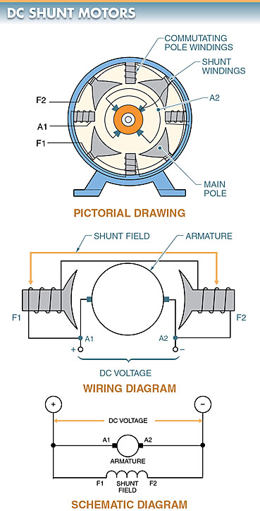
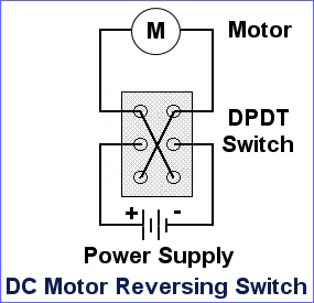
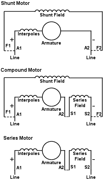
I have a faucet with a solenoid valve controlled by touching the spout. The valve opens/closes depending on the polarity of the input. The power is 6v DC, and there is only 1 single wire coming from the faucet spout. When I place my hand on the faucet, the voltage of the single wire coming from the spout goes from 0.15 to 0.10. The wires and relay is posted below, and I am trying to reverse engineer the circuitry (crude diagram also below) required to achieve this. I have looked in to DPDT relay... Say you want to buy my house, but you're out of money. What can you do? There are some obvious things, like getting a job or taking out a loan, but those things bore you, so here's an interesting solution: you do something extraordinary that convinces me to trust you more than my wife. Then you sign a piece of paper saying: "I owe you one." Assuming what you did to make me trust you was public enough, I might not even need to cash in your promise. Instead, I can go to someone else and han... Shunt wound motors ... Shunt-wound motor generally have 4 wires. Two connect to the (relatively) high resistance field and two connect to the much lower ...
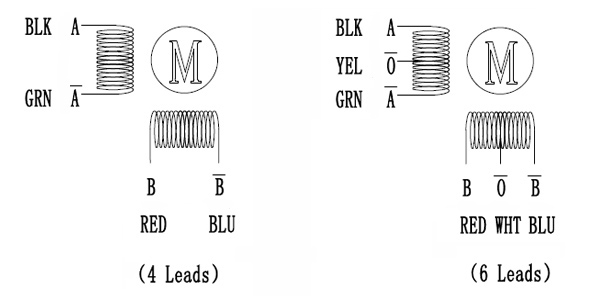
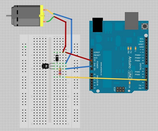
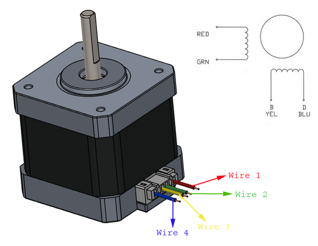
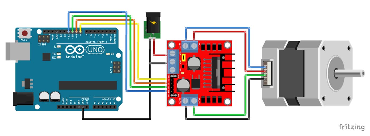
Dc motor wiring diagram 4 wire. **INTRO** I'm running a static test stand to try learn how to pilot BLDC motors. I'd like to pilot the motor with Arduino, while monitoring the current (average DC to the ESC, as the best approximation I can manage) and voltage fed to it, so I can theoretically calculate the RPM of the motor knowing all the constants involved. The final goal of the project is to make a PID to keep the RPM constant a various loads. Also use the battery voltage monitor and current reading as a safety measure to n... Mar 24, 2018 — Hi so I think I've got a shunt motor with four different wires one pair for the field and one for the armature.Help identifying DC motor with 4 wiresJun 30, 2016Driving a 2 phase 4 wire stepper motorJan 1, 2016More results from forum.arduino.cc v- Wiring plan diagram -v http://imgur.com/a/31bRpWj I've looked at like 5 different ancient airsoft forum posts as well as tried to do a little other research. Each different tutorial is trying to do something similar but different OR they already have a mechanism like the bullgear magazine, some of the diagrams have a 3rd green wire (ground?) as well. My plan seems simple I just don't want to f with lipos/electricity and before I spend a bunch of time soldering all these damn dean's connecto... Hello! I recently bought a brushed DC motor that came with an optical encoder attached, however there was no pinout diagram or branding for the encoder. It has 6 pins, so probably 2 to power the motor, 2 to power the encoder, and 2 for data. I have a desktop PSU and would like to know if there is a there a safe way to test the pins so I can wire correctly.
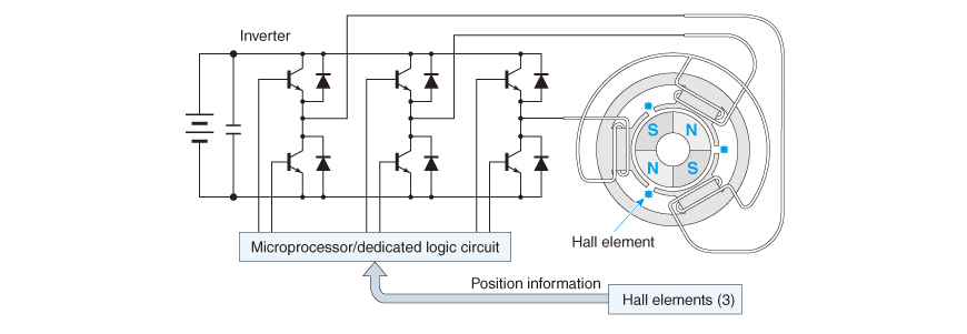
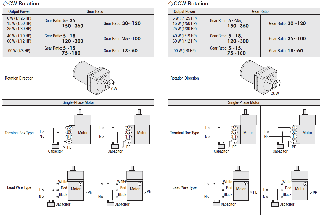
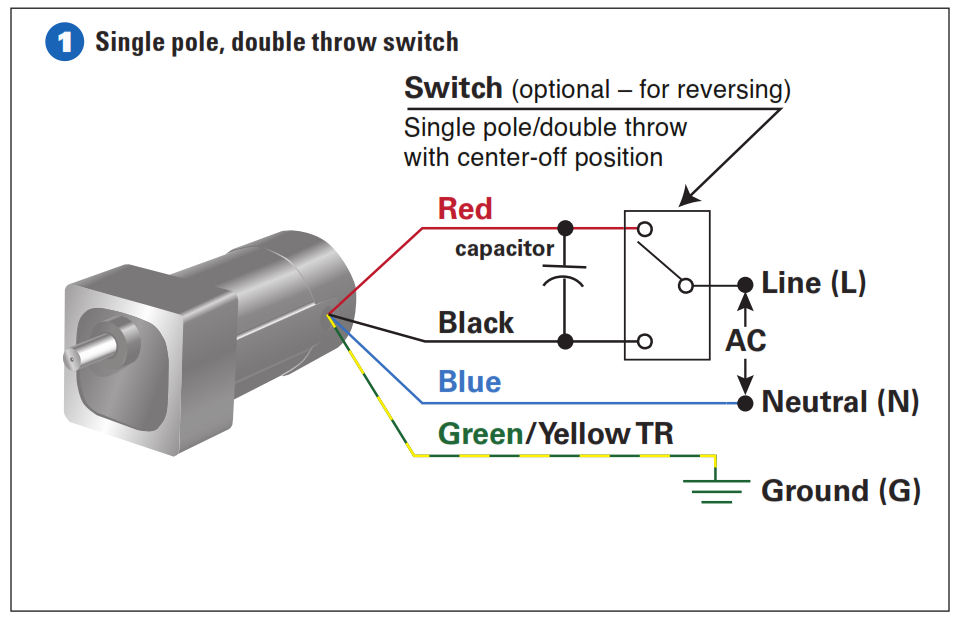
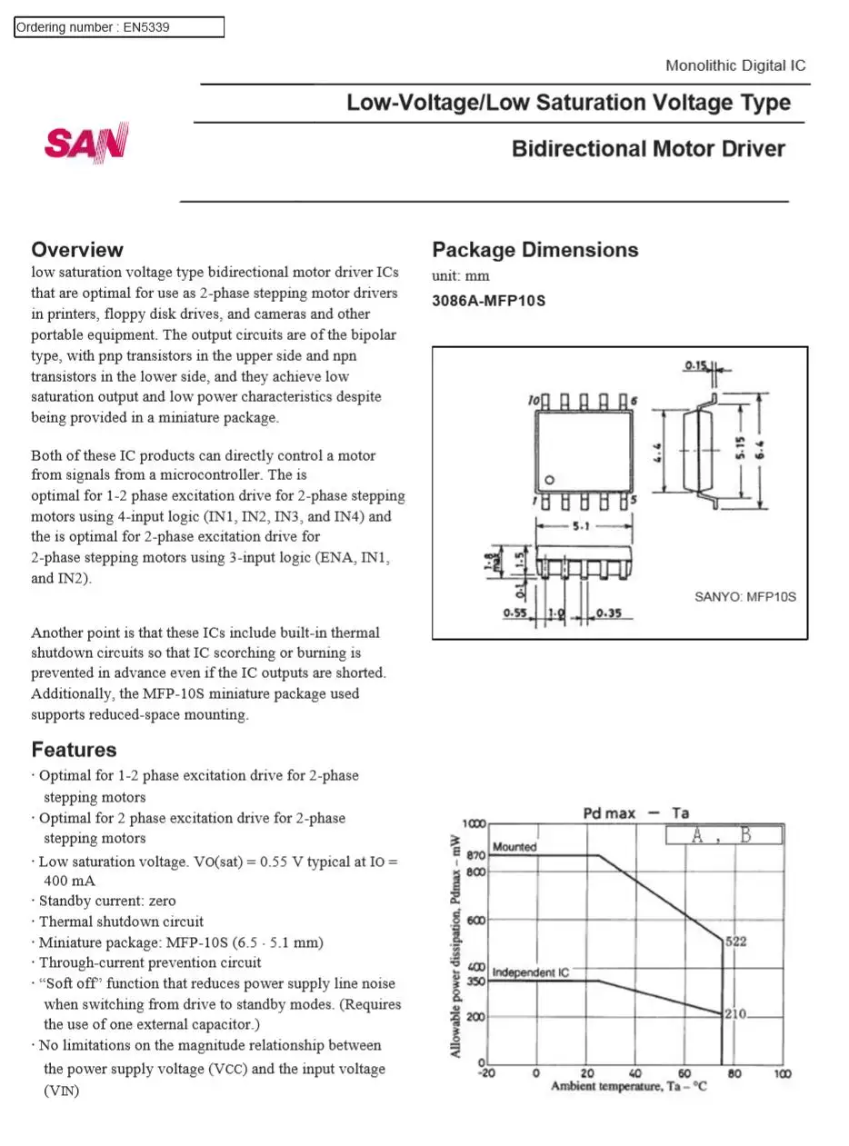
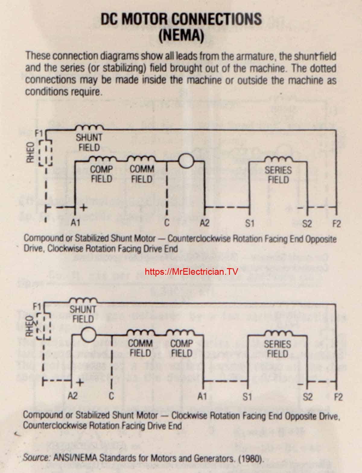
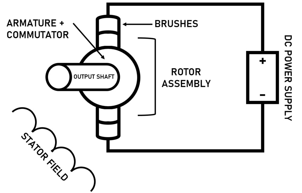
@Kris Scicluna for a motor controller that will be embedded in a product that will be produced serially what would you suggest? Cite. All Answers (4).4 answers · 0 votes: The datasheet attached is contradictory as it shows two wires on the figure and three terminals ... **Brushless DC motors have some significant advantages over their competitors, such as brushed motors, largely because of the electronic commutation. It allows the controller to switch the current promptly and thus regulate the motor’s characteristics effectively. In this article, we’ll consider the peculiarities of a brushless DC motor controller. You will learn about its operating principles as well as the design features and challenges you should know about before building your own device.** ... I am in the process of setting up some automations in Home Assistant to have my irrigation line turned off if it detects a high flow rate via a flow meter with a hall sensor. I think I have the flow meter side handled but need some feedback on the valve side. I bought a Shelly 2.5 for it's 2 relays, a 24 VDC power supply, and this [3 Wire AC/DC ball valve](https://www.amazon.com/Motorized-Stainless-Electrical-U-S-Solid/dp/B06XN5TZX7). The valve uses this wiring diagram to open and close: [Val... Motor Wiring Diagram. D.C. Motor Connections. Your motor will be internally connected according to one of the diagrams shown below. These connections are in.1 page
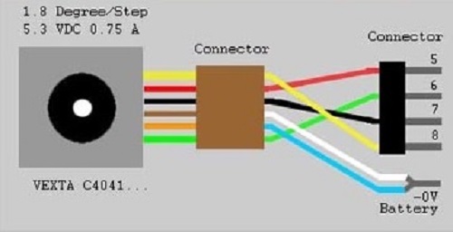
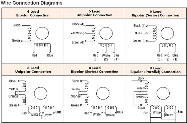
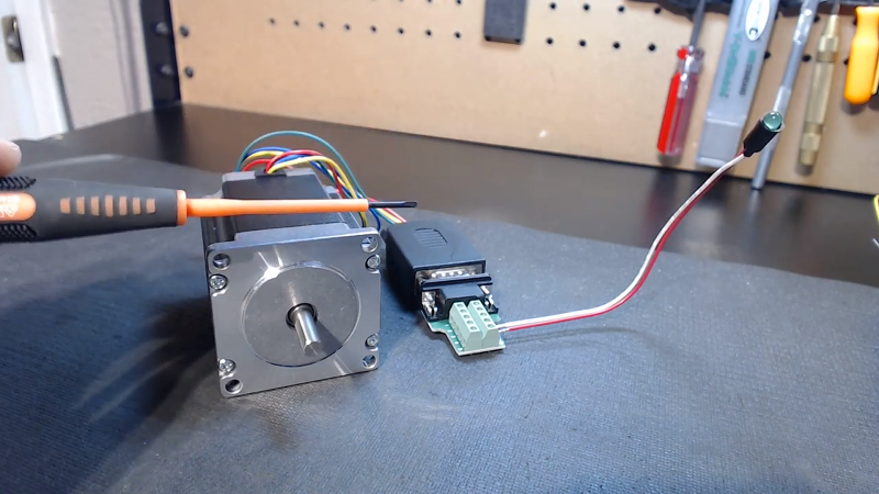
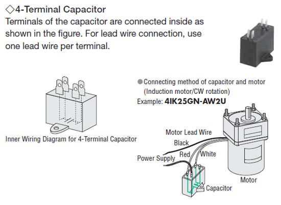
I am working on turning my broken washing machine into a giant cannon. The motor will be pulling the metal cylinder (the part that used to hold the clothes) back to arm it before firing whatever I load into it, so I want to maximize the torque capability in the motor from my homemade driver circuit. The motor is a direct drive brushless motor wired in a Wye configuration. I am driving it with a DC power supply, passing the power through a MOSFET circuit before it goes to the motor. The circuit ... The extra two wires in a 6-wire bipolar stepper allow you to use it as a 4-coil motor instead of a 2-coil, by using the center wire on each coil as a common ... [First](https://www.reddit.com/r/HFY/comments/geph88/meet_the_freak_1/) | [Prev](https://www.reddit.com/r/HFY/comments/jmteq0/meet_the_freak_18/) | [Next](https://www.reddit.com/r/HFY/comments/k3zubv/meet_the_freak_20/) [Discord](https://discord.gg/ZVgVe5m) | [Patreon](https://www.patreon.com/ThisHasNotGoneWell) --- As I relaxed, my breathing and heart rate slowed, and I let it all give way to silence. I'd lived most of my life in the city, and as was the case for most city dwellers, it was... I am not familiar with your motor but you should wire nothing directly to battery or ground. Try wiring the two + leads to the white wire and the two common to ...
Picked up this 3/4HP motor and it looks like it should be AC single-phase based on the diagram, but I can't figure out why it's wired the way it is, or how it's supposed to be wired. Was it possibly connected to an external capacitor? Am I misreading it completely and it's a 3ph or DC motor? 1750RPM makes me think it's a 4-pole AC motor. There's no place for a cap on the side and I wasn't able to find anything googling the brand or part #. Any clues are appreciated. ​ [https://imgur...

This is relevant to a project i’ve been conceptualising. In the this project i plan to use a solenoid (i.e. a magnet passing through coiled wire) to produce electricity. As i desire DC to be produced, the polarity of the energy produced must be swapped when the movement of the magnet changes direction. much like a commutator on an electric motor. Additionally, unless the solenoid is producing power i wish for it to be isolated from the circuit, else current would induce movement in the magnet. ...
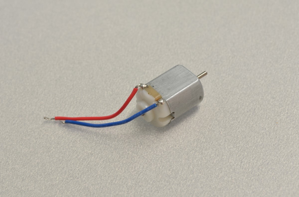
Sep 16, 2014 — Hi all I just got a trophy for being on the forum for 8 years. Time flies :( Well, I have a general question about a 4-wire 4-6V DC motor.How to recognize wires of DC motor ? | All About CircuitsDec 5, 2012Wiring help for a DC motor | All About CircuitsOct 21, 20113 wire DC Motor | All About CircuitsMar 17, 202124v DC reversible motor wiring | All About CircuitsNov 1, 2011More results from forum.allaboutcircuits.com
Jun 2, 2005 — Hi hope some one can help me with this problem i have ....i just won on ebay a 24 v dc Nelco motor with wound field and armature type ...7 posts · Hi, Rob. You haven't given us a lot to work with here. So I guess you'll have to do some detective ...
Shunt wound motors ... Shunt-wound motor generally have 4 wires. Two connect to the (relatively) high resistance field and two connect to the much lower ...
Say you want to buy my house, but you're out of money. What can you do? There are some obvious things, like getting a job or taking out a loan, but those things bore you, so here's an interesting solution: you do something extraordinary that convinces me to trust you more than my wife. Then you sign a piece of paper saying: "I owe you one." Assuming what you did to make me trust you was public enough, I might not even need to cash in your promise. Instead, I can go to someone else and han...
I have a faucet with a solenoid valve controlled by touching the spout. The valve opens/closes depending on the polarity of the input. The power is 6v DC, and there is only 1 single wire coming from the faucet spout. When I place my hand on the faucet, the voltage of the single wire coming from the spout goes from 0.15 to 0.10. The wires and relay is posted below, and I am trying to reverse engineer the circuitry (crude diagram also below) required to achieve this. I have looked in to DPDT relay...


0 Response to "37 dc motor wiring diagram 4 wire"
Post a Comment