37 push button start wiring diagram
Push Button Start System [Advanced Keyless Entry System] System Wiring Diagram. Operation Remote transmitter verification 1. When the push button start is pressed, a push button start signal is input to the start stop unit. 2. When the start stop unit detects a push button start signal, it sends a request outgoing command signal to the LF control unit. 3. Wiring Push Buttons Switch to Click PLC - Acc Automation Wiring to the Click PLC Start PB - X1 - Normally Open Stop PB - X2 - Normally Closed Selector Switch Hand Position - X3 Selector Switch Auto Position - X4 Start Green LED Lamp Output - Y5 Stop Red LED Lamp Output - Y6 Click PLC Program Operation - Push Buttons and Switches
Arduino Push Button Switch wiring and code “Beginners level” Sep 29, 2019 · Arduino Push Button Switch wiring and code– this is a very detailed getting started tutorial on How to use a Push Button Switch with Arduino Uno.As this tutorial is for beginners, so, I will try to cover the extreme basics. No doubt when we first start learning any microcontroller, the very first electronic component that we are introduced to is the LED, and of …
Push button start wiring diagram
PDF Installation Instructions Push Button Start System The PUSH BUTTON START SYSTEM is designed to be installed into a vehicle that utilizes a standard 4 position and 4 terminal 12 VDC automotive rated ignition switch, such as the ... Relay pack wiring (please refer to the relay pack wiring diagram). 1. Operation: The system uses standard automotive rated Form C relays to wirings-diagram.com › push-button-starter-switchPush Button Starter Switch Wiring Diagram - Wirings Diagram Apr 13, 2019 · As stated earlier, the lines at a Push Button Starter Switch Wiring Diagram represents wires. At times, the wires will cross. But, it does not imply link between the wires. Injunction of 2 wires is generally indicated by black dot on the junction of two lines. There’ll be primary lines that are represented by L1, L2, L3, and so on. Single Push Button ON OFF Relay Latching Switch Circuit ... one push button start stop relay. This is ON OFF switch circuit by using the single pushbutton switch. In this circuit used 2 relays. Make the connection as the given diagram. When you give the supply to the connection, the output load is in OFF. Once press the switch for 1 second then the load is turned on, But again press the same pushbutton ...
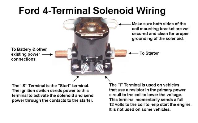
Push button start wiring diagram. PDF Basic Kit - ididit Place your foot on the Brake, then depress of the Start Button and your starter will begin to "crank" and continue until the button is released. The Start Button LED will glow while your vehicle is running. tO StOP yOUR ENGINE: Place your foot on the Brake, Push and HOLD the Start Button for 2 seconds and your engine will shut off. PowerFlex 525 VFD Setup - Programming Parameters Wiring ... In terms of wiring, the simplest method of controlling the drive without a PLC is through the use of a start and stop push buttons. The diagram below (taken from the manual) illustrates how this can be accomplished. Note that although this method is simple, it’s not the recommended way to use these drives. How to Install a Push-to-Exit Button - getkisi.com A crucial step in setting up your push-to-exit button is properly wiring all the components. In an IP system like Kisi, this will involve the door lock, the access reader, the controller, the power supply, and the push-to-exit button (as well as optional contact sensors). The following diagram outlines the setup with an electric strike lock. ADVANCED KEYS Push-Start Ignition System PUSH -START IGNITION CONTROL MODULE WIRING DIAGRAM Toyota / Lexus OEM Push - Start Button Wire the backup relays to the controller/vehicle according to the following diagram External Backup Ignition Relays Connection Purple Negative START White Red Blue Green Black Red Yellow Positive START Battery +12v (IGNITION 2) ON 2 (IGNITION 1) ON 1 ...
A Complete Guide to Push Button Switches | RS Components Push Button Switch Diagram. The diagram to the right demonstrates how a push button can be used alongside an ignition switch as part of a quick start ignition circuit. This schematic shows the basic circuit design and wire layout required for this particular application. Awesome Push Button Ignition - Instructables 5 steps1.For this project you will need: One Single Pole Double Throw Relay (a SPST normally open will work as well) One Momentary switch, Normally open (toggle or ...2.Here you will need to get inside your dashboard to where your ignition harness is. This is near the keyhole. Once you get to this bundle of wires you will ...3.Now we will solder together the chain of switches and wires and buttons and relays to make this all work. This is by far the easiest step. Basically the way ... 800-2.0 Typical Wiring Diagrams for Push Button Control ... Typical Wiring Diagrams For Push Button Control Stations 3 Genera/ Information @ Each circuit is illustrated with a control circuit (continued) schematic or line diagram and a control station wiring diagram. l The schematic or line diagram includes all the components of the control circuit and indicates their function. VFD Start Stop Wiring Diagram - Electrical4u VFD Start Stop Wiring Diagram: I am here with giving you a VFD start stop wiring diagram for running a VFD through panel board push button and keypad of the VFD (It is called HMI).. Vfd is a short form of variable frequency drive or variable voltage variable frequency drive.The VFDs are working based on changing the input frequency and input voltage of the motor, we can change the speed of the ...
Push Button Start??? - S-10 Forum You should use a distribution block to make it easier to mount the wiring, and condense it down and use a 4 ga to the actual switch. If you decide to do a push button, I HIGHLY suggest a hidden switch that deactivates the ignition or is needed for you to start the truck. One example would be a switch that you push on with your foot for it to crank. Push Button Switch Wiring Diagram - Wiring Tech Push button switch wiring diagram - Wiring Diagram for Push button Start New Push button Switch Wiring Diagram. Here is an easy to follow instructional video with all install diagrams for our range of STEDI OEM and Carling Type switches. Arduino LED Switch On By Push Button Switch Off By IR Three Wire Control Multiple […] GalloTech Push Button Start | Manuals | Wiring Diagrams GTStarter 3RS (with remote start): Installation Manual GTS-3 /3RS Power Door Lock Actuator: Installation Manual Custom SS Push Button Switch: Installation Manual Door Popper Wiring Diagram: Installation Manual Make, Model, Year OEM Wiring Diagrams: Steering Column & Security By-Pass Options: Installation Manual Discontinued Product Manuals PDF GI-2.0: Typical Wiring Diagrams - Rockwell Automation WIRING DIAGRAMS Bulletin 609 manual starters are operated by "START-STOP" push buttons mounted on the front of the starter. They are used in applications which do not require undervoltage protection. Wiring diagrams do not show the operating mechanism since it is not electrically controlled.
Push button start switch conversion : MGA Forum : MG ...
uwiring.com › push-button-start-wiring-diagramPush Button Start Wiring Diagram - U Wiring Nov 30, 2021 · PUSH -START IGNITION CONTROL MODULE WIRING DIAGRAM Toyota Lexus OEM Push – Start Button Wire the backup relays to the controllervehicle according to the following diagram External Backup Ignition Relays Connection Purple Negative START White Red Blue Green Black Red Yellow Positive START Battery 12v IGNITION 2 ON 2 IGNITION 1 ON 1.
please help !installing pivot push start - Honda-Tech - Honda ...
Wiring Diagram 4+1start Push Carbon Fiber Panel Button Car ... Wiring diagram included. . 4+1Start Push Chrome Panel Button Car Ignition Engine Racing Toggle Switch (Fits: Dodge A Pickup) . Carbon Fiber Car Ignition Switch Panel Toggle Engine Start Push Button. 30A Racing Auto Engine Start Push Button Ignition Switch Panel, 5 in 1 Toggle On/Off button of all kinds of electrical equipment for inside and ...

22mm Black Body Push Button 6-Pin ON/OFF | MGI SpeedWare
Start Stop Push Button Wiring Diagram - Wiring Diagram Push On Start Stop Switch Wiring Diagram - All Wiring Diagram - Start Stop Push Button Wiring Diagram Wiring Diagram contains several detailed illustrations that present the relationship of varied things. It includes directions and diagrams for different kinds of wiring methods along with other items like lights, windows, and so forth.
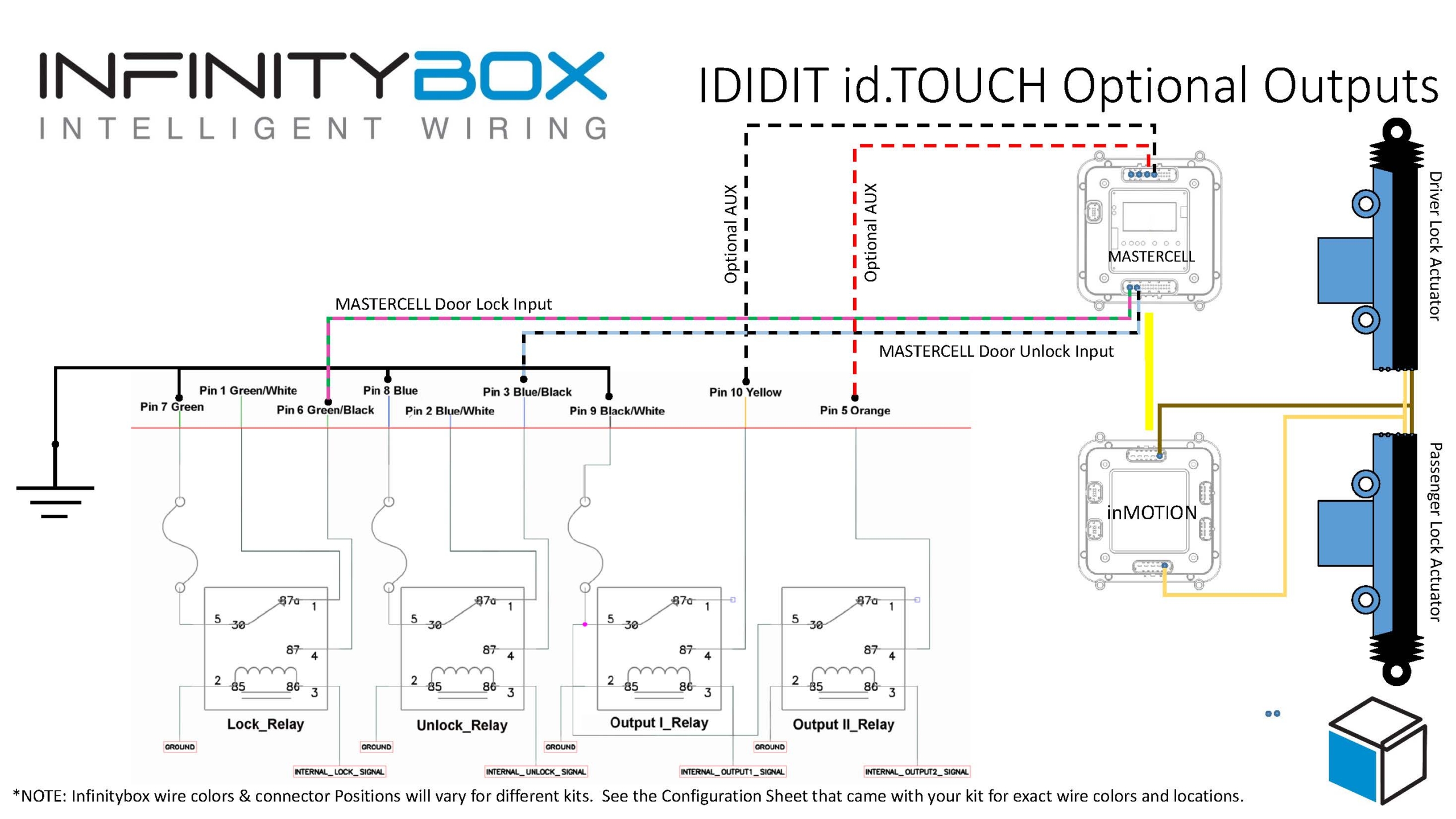
push button start Archives - Infinitybox
Push Button Starter Install - Pantera Place Now push the start button, there should be 12 volts on pin 85 only when holding the start button down. Release the start button and confirm there is no voltage present on pin 85. Providing everything checks OK, turn the ignition switch off. Put the relay in the socket. Make sure the car is in neutral. Verify the start function to start the car.

Buy BANVIE Car RFID Leather Key Push to Start Ignition kit ...
Two Wire Control | Start Stop Jog Control Circuit In Figure 1 there are two start and two stop push-button switches. As is usual, the start push-buttons are normally open and the stop push-buttons are normally closed. They have been labelled 'start 1', 'start 2', 'stop 1' and 'stop 2' for clarity. Figure 1 Two start and stop control positions in a circuit

Push Button Starter How To with and without a relay.
annawiringdiagram.com › push-button-start-wiringPush Button Start Wiring Diagram - Wiring Diagram Jul 22, 2020 · Three Wire Control Multiple Stations – Push Button Start Wiring Diagram Wiring Diagram contains numerous comprehensive illustrations that display the relationship of assorted products. It includes instructions and diagrams for various types of wiring strategies as well as other items like lights, windows, and so on.

Push button Ignition Switch Wiring Diagram New | Boat wiring ...
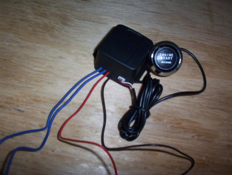
PDF PUSH BUTTON START INSTALLATION MANUAL - KP Technologies 2. Press and hold the Start/Stop button for ~1 second then release 3. The Ignition Cut Output will activate for ~3 seconds to kill the vehicle. After ~3 seconds the ignition will turn back on, even though the motor is no longer running With the tachometer input hooked up correctly the KPtechnologies Push Button Start
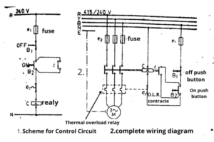
DOL Starter Scheme and Wiring Diagram : Electric guider
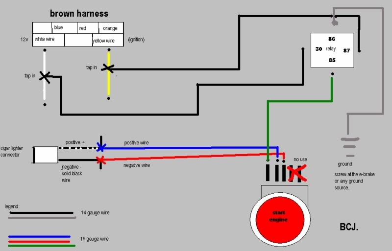
DIY: push start button ( wiring diagram) | 8th Generation ... a simple wiring diagram for push start button... i recommend using a T-tap for the 12V and ignition wire on the brown harness. WARNING: THE S2000 PSB WON'T FIT DIRECTLY ON THE HAZARD'S LOCATION. YOU HAVE TO MODIFY THE BUTTON A LOT. im not gonna post the step-by-step...

DIY: Push Button Starter w/o S2000 button - Honda Civic Forum
Doorbell Wiring Diagram: A Complete Tutorial | EdrawMax Wiring it wrong will create problems like it may give electric shocks when you press the push button, short-circuit in the chime or the bell button, or it may not produce the sound. The need to make a doorbell wiring diagram comes when you want to make it and supply it …
Awesome Push Button Ignition : 5 Steps (with Pictures ...
I want to utilize a push button starter switch instead of ... The first connection possibility involves the push button starter only working when the ignition is turned to the "On" position. To accomplish this, splice or double a 12-gauge jumper wire off of the pink wire at the ignition switch connection and take that jumper wire over to one side of the push button switch.
Jtron® DC 12 V 50 A Red Light Push Start Ignition Switch für ...
How to Install Toggle Switches & a Push Button Start | It ... Push start buttons and toggle switches allow you to operate a vehicle with the push of a button. Though these two devices are similar in their use and installation, the process varies slightly. Typically, people install toggle switches and push start buttons in automobiles or other motorized vehicles. However, there ...
Toggle and Push button wiring | Pirate 4x4
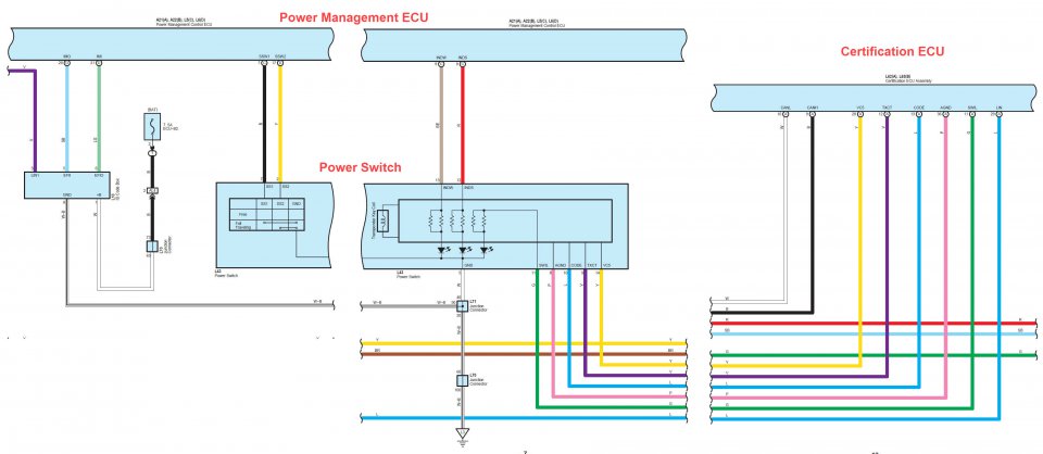
2021 Toyota Tundra, Alarm/Remote Start Wiring Feb 07, 2022 · 2021 Toyota Tundra, Alarm/Remote Start Wiring - Hello - Might anyone have a remote start / alarm diagram for a 2021 Toyota Tundra with push button start? Any help would be greatly appreciated. Thanks in advance....

How To: S2000 Push Button Start | Team Integra Forums
How to Install a Push Button Start Ignition on an Older Car Turn the key in the ignition to test the voltage. Mark all of the ignition wires that you'll need to work with using the supplied wiring diagram ...Aug 5, 2021 · Uploaded by Mizta Shy
Anyone have the 2012 v POWER button wiring diagram handy ...
How to Convert a Basic Wiring Diagram to a PLC ... - RealPars Mar 18, 2019 · The start push button will energize the circuit and the auxiliary contact will keep it energized. I hope this article has been helpful in the transition from wiring diagrams to PLC programming. This was a very basic program that can run a motor.

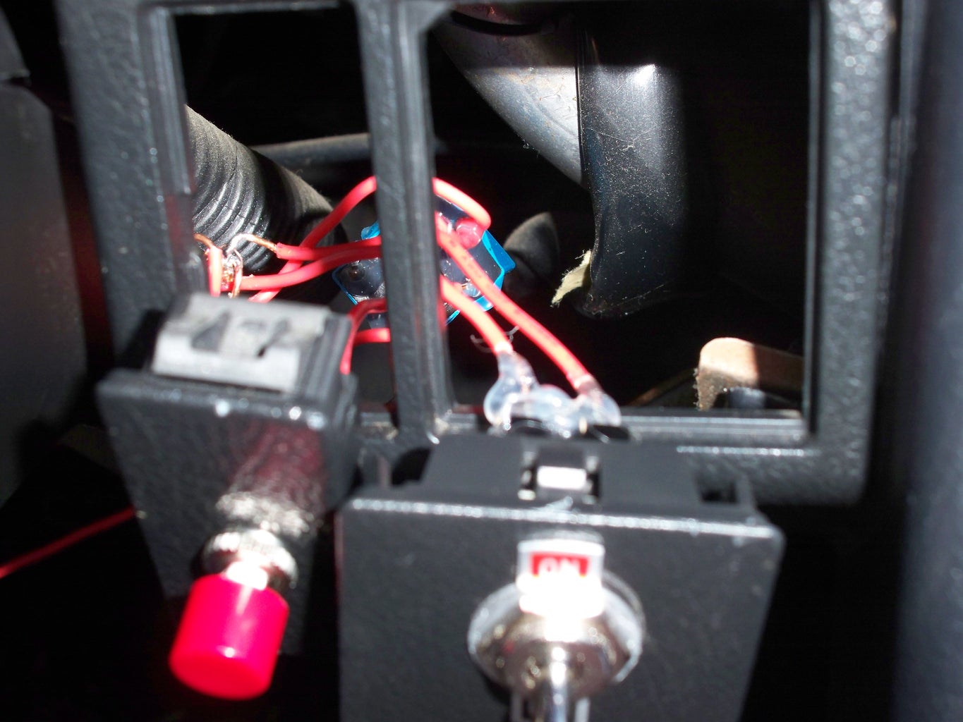
Push button ignition installed, pictures! | TDIClub Forums
Basic wiring diagram for NO / NC push button start switch ... Basic wiring diagram for NO / NC push button start switch Full disclosure - I have no business trying to wire anything up. I feel like this should be easily found but I've watched too many YouTube videos and google searches and still cannot understand how to wire up my switch correctly.
All Wiring Diagrams for Dodge Ram Van B1999 1500 ...
How to Convert Car to Push Button Start - Vehicle Jack.Com The hot-wiring process involves two wire ends touching each other to produce ignition whereas a push-button start will use a switch instead. If your key does not work or you have lost it, you will be needing an in-depth- diagram for this purpose.

DOL Starter Connection and Wiring Diagram with OLR - ETechnoG
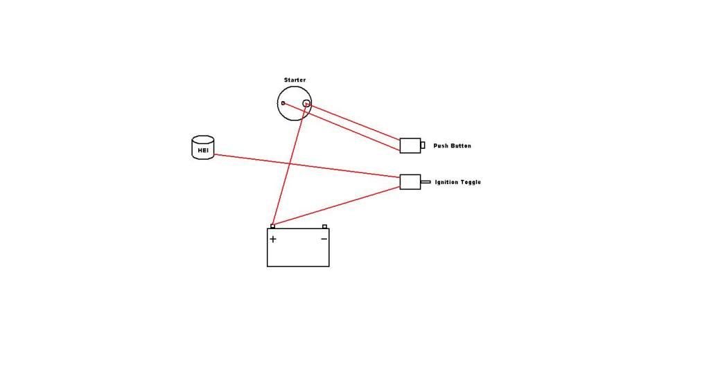
Simple Car Wiring Diagram - The Wiring 800 x 600 px, source: I'm looking for a simple wiring diagram for a street stock. ... power switch, push button start, starter, Hei dist. Brakes, Electrical, Hitches, Weight. Wiring Diagram is a technique for describing configuration of electrical equipment installation, for example installation of electrical equipment in substation in CB ...

How to : Install MoboKey Cam Pro in Push Start Button Car ...
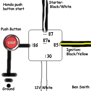
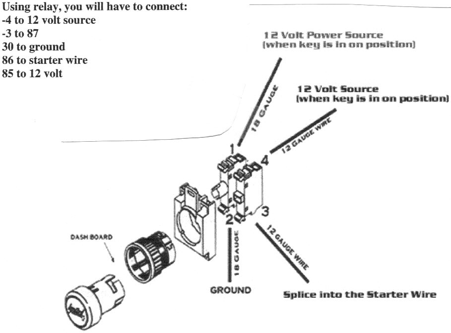
push start button / relay diagram - Electronics Forums 30 - Push Start Button Output 87 - STR wire 85 - Battery wire Relay 2 provides power to the starter when the button is pressed. I believe this solves my problem. Hopefully someone can chime in. Edit: Looks like I may need 3 as I need to also cut the IG2 wire during starting.
Pushbutton start? - DodgeForum.com
Push To Start Kit | Purchase a Push Button Start Kit ... Push to Start Conversion Kits. Adding a push to start kit for your vehicle makes engine starting easier and provides a more modern touch. JEGS offers a push button start kit with remote start selection for cars and trucks from top manufacturers such as Ididit, Flaming River, and others.Each push to start kit is made from high quality components and assembly so you can …
Push Button Start | Dodge Durango Forum
Start Stop Push Button Wiring Diagram - Wirings Diagram According to earlier, the lines at a Start Stop Push Button Wiring Diagram signifies wires. At times, the wires will cross. However, it doesn't mean link between the wires. Injunction of 2 wires is usually indicated by black dot in the intersection of 2 lines.
Gauging: S2K Push Button Start - Unofficial Honda FIT Forums
shapovmusic.com › how-to-wire-a-push-button-starthow to wire a push button start diagram - shapovmusic.com Step 1: Obtain a circuit diagram. Step 2: Locate all components that need wiring. Step 3: Connect the switch to ground. Step 4: Connect the switch to the Solenoid. Step 5: Wire the magneto to the switch. Step 6: Provide voltage by connecting the battery.

Db Electrical PMGR starter wiring | Vintage Mustang Forums
PDF User Manual of EC002 - FCC ID Push start button x1 Alarm high frequency antenna: x1(with red color connector) PKE antenna: x2 Touc h password keypad: x1 6P ignition wire harness: x1 20P wire harness: x1 3 color (orange, white, yellow) GWR wire x1 or (shock sensor x1) Note: if the device equip with 3 color (orange, white, yellow) GWR wire, then there is no shock sensor in the
Push Button Start and Kill Switch / Ignition Bypass - Honda ...
› push-button-start-wiringpush button start wiring diagram - Wiring Diagram and Schematics Dec 13, 2021 · How to install mobokey cam pro in push start on car a complete guide switches rs components diagram hyundai forums diy wiring page 25 8th generation honda civic forum banvie rfid leather key ignition kit engine stop switch keyless go system with online taiwan b083v4jgbk multiple stations toggle ih8mud technical anyone still use the h m b dodge ...
Technical - ANYONE STILL USE PUSH BUTTON START? | The H.A.M.B.
Start Stop wiring Basics - YouTube This video is a step by step explanation of wiring Start Stop basics. As long as you follow the ladder diagram and take it one wire at a time its simple.This...
ignition toggle with push button start | IH8MUD Forum
EASY! How to COMPLETELY WIRE a Push Button Start ... - YouTube THIS IS MY MOST VIEWED VIDEO!!! Use my Amazon links to buy whatever you need!!WE HIT 1000 SUBS!!! NOW LIKE THE VIDEO HAHAHAWe go step by step in wiring up a ...

TUTORIAL: Engine start button box : r/pcmods
Single Push Button ON OFF Relay Latching Switch Circuit ... one push button start stop relay. This is ON OFF switch circuit by using the single pushbutton switch. In this circuit used 2 relays. Make the connection as the given diagram. When you give the supply to the connection, the output load is in OFF. Once press the switch for 1 second then the load is turned on, But again press the same pushbutton ...

Wiring for Push Button Use - 4QD - Electric Motor Control
wirings-diagram.com › push-button-starter-switchPush Button Starter Switch Wiring Diagram - Wirings Diagram Apr 13, 2019 · As stated earlier, the lines at a Push Button Starter Switch Wiring Diagram represents wires. At times, the wires will cross. But, it does not imply link between the wires. Injunction of 2 wires is generally indicated by black dot on the junction of two lines. There’ll be primary lines that are represented by L1, L2, L3, and so on.

High quality 12V Universal LED Illumination pivot install ...
PDF Installation Instructions Push Button Start System The PUSH BUTTON START SYSTEM is designed to be installed into a vehicle that utilizes a standard 4 position and 4 terminal 12 VDC automotive rated ignition switch, such as the ... Relay pack wiring (please refer to the relay pack wiring diagram). 1. Operation: The system uses standard automotive rated Form C relays to
Push Button Start - G35Driver - Infiniti G35 & G37 Forum ...
DIY: push start button ( wiring diagram) | Page 27 | 8th ...

Download Start Stop Push Button Wiring Diagram Free for ...

Fuzbaxy 12V Ignition Switch Panel 5 in 1 Racing Car Engine Start Push Button LED Toggle for Racing Car Truck
Doing a push button starter switch set up and need a little ...

Start Stop Push Button Wiring Diagram für Android - APK ...

Push Button Start Installation Instructions
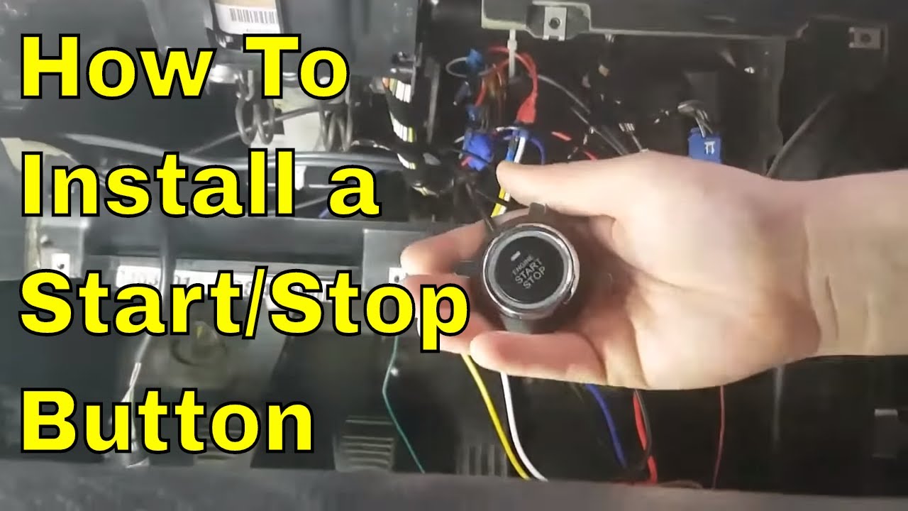
how to install a universal engine start stop button
Push button diagram | Hyundai Forums
0 Response to "37 push button start wiring diagram"
Post a Comment