38 pilot brake controller wiring diagram
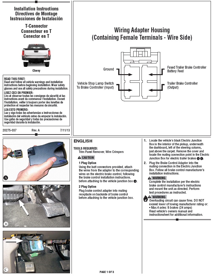
Brake force electric brake controller wiring diagram. The black wire is the power supply line to the brake control. Wiring instructions for electronic brake controls p n 4399 rev k generic wiring diagram read this first. Auxiliary connection is optional it may be connected to any 12v to 24v constant power source or left unconnected. Jan 11, 2018 · The REESE Towpower PILOT digital brake control designed for one to three for quick installation, just get the right harness and wiring is just plug and go. DRAW-TITE VEHICLE BRAKE CONTROL WIRING DIAGRAM.
knobon the control. 3. While applying the manual slide knobturn power knob until display reads 4.0. 4. Drive tow vehicle and trailer on a dry level paved surface at 25 mph and apply manual slide knob. READ THIS FIRST: Read and follow all instructions carefully before wiring brake control. Keep these instructions with the brake control for ...

Pilot brake controller wiring diagram
Electrical Wiring Trailers require electrical hook-ups that make towing safer for you and others on the road. In fact, while each state has its own laws and regulations governing everything from size limits to weight restrictions, the one thing they all have in common is that your trailer must be wired for tail lights, brake lights and turn ... PILOT INSTRUCTIONS. P/N 95003, Rev. ... before installing or operating the Brake. Control. ... NOTE: If using a wiring harness, apply brake pedal or manual ... Test your brake controller.
Pilot brake controller wiring diagram. If your towing a trailer with brakes you have to have a brake controller to activate your brakes! In this video we review the Pilot ... Valve Group - Control Bank Lines Group - Pilot Bank-4 Bank-3 Bank-2 9T-7248 9T-7250 9T-7249 Tank Group - Hydraulic Control Group - Brake Lines Group - Pump VALVE GP CONTROL BANK 2 NOTE O 9T-7248 BANK3 NOTE P 9T-7249 BANK 4 NOTE Q 9T-7250 TANK GP HYDRAULIC 112-2908 NOTE M 112-2967 STRAINER AS 110-3024 STRAINER CAP VALVE GP BREAKER/RELIEF 6S-4767 ... Pro Series Pilot® Brake Control for 1 to 3 Axle Trailers. Product Features. Pilot has a dark, smoke lens that is ideal for direct light applications, creating optimum visibility to read the large, two-digit display. Pilot has flexible mounting options and can be installed in any direction. Our microprocessor allows you the ability to read the ... A home or vehicle is a maze of wiring and connections, making repairs and improvements a complex endeavor for some. Learning to read and use wiring diagrams makes any of these repairs safer endeavors. These simple visual representations all...
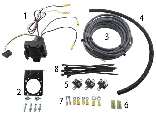
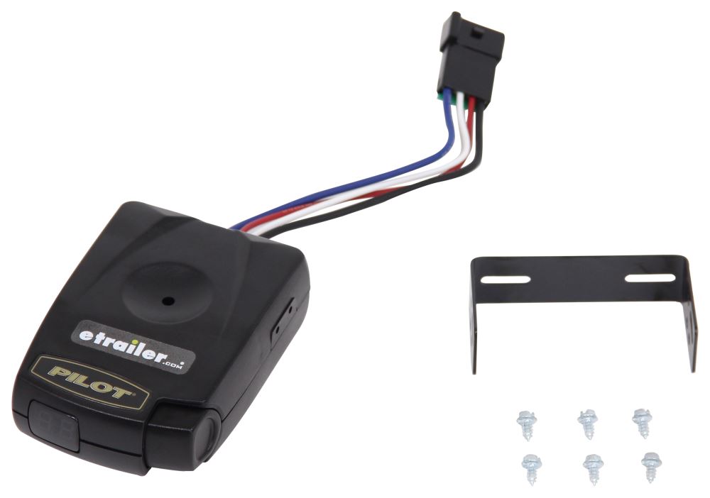
Wiring Kit for 2 to 4 Brake Control Systems, Includes 25 ft. 12-2 Duplex Wire, 20 Amp Circuit Breaker and Attaching Terminals. $25.25. 20506. Wiring Kit for 6 to 8 Brake Control Systems, Includes 25 ft. 12-2 Duplex Wire, 30 Amp Circuit Breaker and Attaching Terminals. $49.45. This item: Reese Pilot Brake Controller, Black (74378) $35.39. In Stock. Ships from and sold by Amazon.com. FREE Shipping. Reese Towpower 7805011 Brake Control Wiring Harness. $16.90. In Stock. Ships from and sold by Amazon.com. 7 Pin Trailer Wiring Diagram With Brakes – 7 pin flat trailer wiring diagram with brakes, 7 pin rv trailer wiring diagram with brakes, 7 pin trailer wiring diagram with brakes, Every electrical arrangement is made up of various different parts. Each component ought to be set and connected with different parts in particular manner. If not, the arrangement will not function as it ought to be. Read Book Pilot Brake Controller Manual File Type RockAuto Jan 28, 1999 · At this time the controller asked the pilot to recycle his transponder code, and the pilot did so. and an electrically actuated speed brake that deploys from the fuselage belly. The switches for the electric trim and the speed
A vehicle wiring diagram is a lot like a road map, according to Search Auto Parts. Wiring diagrams are laid out similar to a road map because the diagrams show how each major electrical system, individual circuit and sub-system connects, th... The Pilot brake control part 13523 will work mounted at any angle, even up side down. -SAVANNAH 6/17/2016 8:13:46 AM. Do you have the electric brake control in the stores or would it have to be ordered ... are brake controller wiring adapters available for 2014 dodge caravan The controller can not adjust the end points of the Gear Doors, for this please proceed to adjust mechanically using different length servo arms, push rods or control horns to obtain the required travel. 3- Disclaimer. All Pilot-RC products are guaranteed against defects for 30 days of your receiving the model. Jan 28, 1999 · At this time the controller asked the pilot to recycle his transponder code, and the pilot did so. and an electrically actuated speed brake that deploys from the fuselage belly. The switches for the electric trim and the speed brake were located on the side stick controller. 1996, was also in the pilot's medical file it stated ...
Pilot Brake Controller-SPECIAL PURCHASE- 1 to 3 Axles
Pilot® Trailer Brake Controller, Timed, 1 to 3 Axles · Large easy to read dual digital display shows: · Properly wired control · Voltage output to brakes (vs.

Amazon.com: Reese Pilot Brake Controller, Black (74378 ...
Pilot Trailer Brake Controller Wiring DiagramThis page has wire diagrams for many electric options including wires for trailer lights brakes alt power and connectors. Break away systems may be added to the service brake circuit. As stated earlier the traces in a Tekonsha Brake Controller Wiring Diagram signifies wires.

Custom Wiring Connector (4-Way Flat Output) SKU #56170 for ...
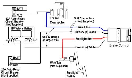
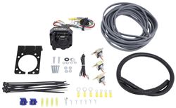
The blue wire carries the output voltage for the controller, and would attach to the brake output pin on the trailer connector. We offer a brake controller install kit, part # ETBC7 . The kit includes everything necessary for installing a controller, including the trailer connector, the breakers mentioned above, and all wire and hardware.
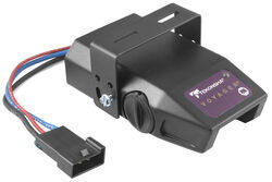
Wiring Diagram Tekonsha Voyager Brake Controller # 39510 ...
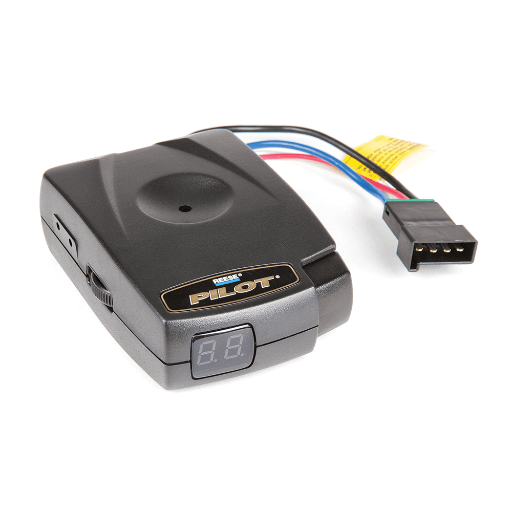
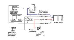
The blue wire carries the brake controller output voltage, the white wire provides the ground connection and is usually ran to the negative battery terminal, the black wire is the 12-volt power supply, and the red wire typically connects to the brake stoplight switch located above the brake pedal. This connection activates the trailer brakes once the brake pedal is applied.

Trailer Brake Controller Harness (Packaged) SKU #51393 for ...
According to previous, the lines in a Ford Trailer Brake Controller Wiring Diagram signifies wires. Sometimes, the wires will cross. However, it does not mean connection between the cables. Injunction of two wires is generally indicated by black dot on the junction of two lines.
Brake control install write up. | Tacoma World
How to install a trailer brake controller on a GM van without a quick connect plug. It's pretty easy.Get the Activator II here: http://amzn.to/2jSon4lGet the...
Reese Towpower Pilot Digital Brake Control
Installing a brake controller involves disconnecting the vehicle battery, mounting the brake controller onto dash and plugging the unit in with a vehicle-specific wiring harness. If your vehicle is not equipped with a plug-and-play harness, you can also splice in wiring for connecting a brake controller. In this guide, we cover step-by-step how to install a brake controller.
Brake Controller Installation: Starting from Scratch ...
PILOT Brake Controller. locate the slide knob and power knob (items A and B in the linked instructions' diagram). Pilot Brake Electronic Brake Controller - Time Delayed Wiring Instructions for Pilot Trailer Brake Control, Part # · What Can Cause Troubleshooting a Reese Pilot Brake Controller that Says It's Connected all the Time.
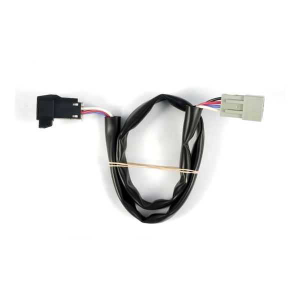
Curt Brake Controller Wiring Harness 51392
The Pilot trailer brake control has just made owning and operating a digital brake control easier than ever. The dark, smoke lens is ideal for direct light ...
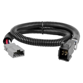
Under Dash Harness Connector for Trailer Electric Brake Controller
A brake controller wiring installation kit makes light work! The following diagram is a general guide for wiring common brake controllers into cars. Please ensure you have the correct gauge wire and we do recommend you use an auto-electrician to wire the brake controller into your car.
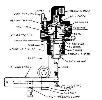
POWER BRAKE CONTROL VALVE SYSTEM
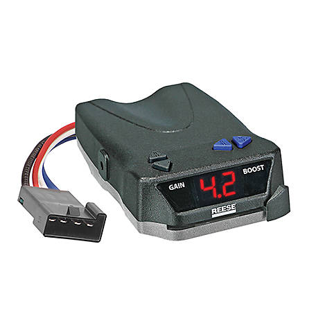
Components of the Brake Control A. Power Buttons B. Boost Button C. Menu/Options Button D. LCD Display Screen E. Connector (For Wiring Harness) F. Mounting Hole (1 per side) G. Manual Knob Important Facts to Remember 1. Do not mount or activate RF generating items (cell phones, two way radios) near (less than 12") the brake control. 2.
Brake Controller Installation: Starting from Scratch ...
On the pilot brake controller item 80550 the wiring is as follows. To the right there is a picture that has a diagram of how most brake controllers wire up if you click it you will be able to see an enlarged version of the picture.

Pro Series 80550 PILOT FOR 1 TO 3 AXLE TRAILERS User Manual ...
Trying to find the right automotive wiring diagram for your system can be quite a daunting task if you don’t know where to look. Luckily, there are some places that may have just what you need. Here’s where to start. Before you search for a...
Honda Ridgeline Brake Controller Installation Instructions
File Type PDF Pilot Brake Controller Manual File Type Aug 04, 2016 · Snpadragon high range mortar is a static defence. to use enter the gunner seat and aim it at where you want to hit. effective range is 300-500m flat ground. but can be extended by elevating the gun by holding left mouse. numpad 8 and 9 fires shells.
Wiring Diagram for Tekonsha PowerTrac Brake Controller ...
Some HONDA Car Manuals PDF & Wiring Diagrams above the page - Civic, CR-V, Fit, Ridgeline, S2000, Accord, Odyssey, Element, Pilot; Honda Car EWDs.. In 1946, the Japanese automobile company Honda was created. Its founder Soichiro Honda did not have the necessary engineering education, but he compensated for all the gaps with risk and accurate instinct.
Honda Pilot Trailer Brake Controllers | Proportional, Time Based
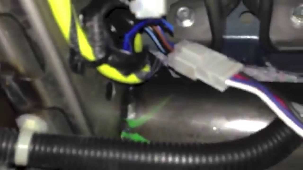
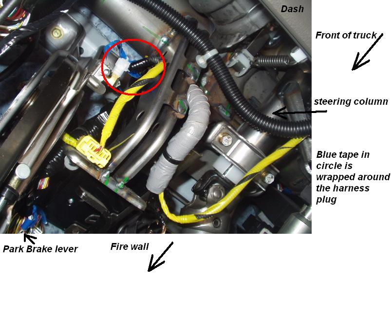
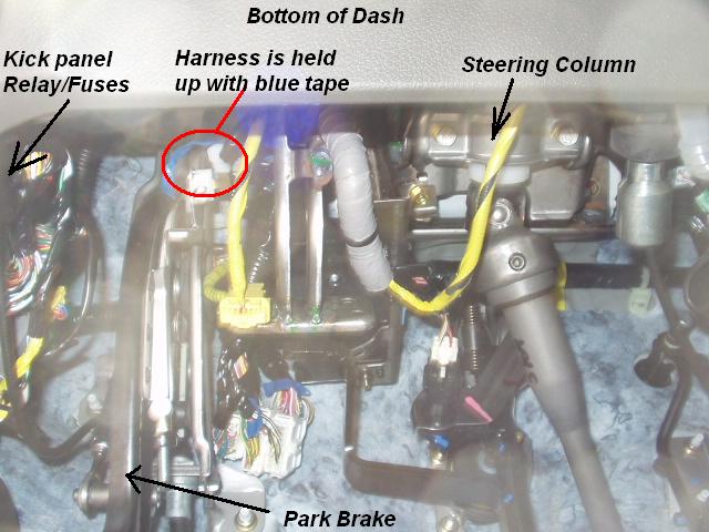
Jun 24, 2015 · With the 2016 pilot wiring harness option you get a plug under the dash on the left sidewall that a 2012-2016 adapter plug will fit, also supplied with the harness kit.This adapter plug needs to be wired to the plug for the back your particular brand of electric brake controller which is supplied by the brake controller company.
Reese Towpower Towing Brake Control Harness, 18 in ...
The control circuit is separate from the motor circuit. The control circuit may not be at the same voltage as the power circuit. When the voltage of the control and power circuits is the same, it is referred to as Common Control. If the volt-ages are different, it is called Separate Control. Figure 4. Typical Starter Wiring Diagram — Three-Phase

Brake Controller | Nissan Titan Forum
Presented by Hayman Reese technical towing expert Gary Gardiner, watch the typical installation process of Hayman Reese Brake Controllers, including end-to-e...
06-08 Honda Pilot Reverse Wire | Honda Pilot - Honda Pilot Forums
The brake control must be installed with a 12 volt negative ground system. (To install with a positive ground system use Tekonsha ® P/N 3191.) 2. WARNING Reversing BLACK and WHITE wires or improper wiring will damage or destroy brake control. 3. WARNING Be sure to solidly connect all four wires or brake control will not function properly. 4.

Amazon.com: Tekonsha 80550 Pro Series Pilot Brake Control ...
Our units are designed for brake controls manufactured with electrical wiring mounted on the back of the unit, otherwise known as a pigtail.
Reese Pilot Trailer Brake Control for 15-22 RAM 1500 2500 ...
7-Way Flat Pin Connector w/Brake Control Wiring #118799. Stock# 5223298. The 7-Way Flat Pin Pre-wired Brake Control Wiring Adapter allows you to quickly and easily wire your vehicle to accept a brake controller by utilizing your existing flat 4 connector. $72.50.

Tekonsha | 1 - Plug Adapters
Test your brake controller.
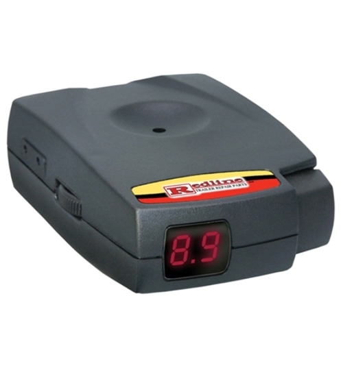
Redline Pilot Brake Control TA1200
PILOT INSTRUCTIONS. P/N 95003, Rev. ... before installing or operating the Brake. Control. ... NOTE: If using a wiring harness, apply brake pedal or manual ...
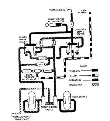
POWER BRAKE CONTROL VALVE SYSTEM
Electrical Wiring Trailers require electrical hook-ups that make towing safer for you and others on the road. In fact, while each state has its own laws and regulations governing everything from size limits to weight restrictions, the one thing they all have in common is that your trailer must be wired for tail lights, brake lights and turn ...

Tekonsha | 3070-S | Trailer Brake Controller Harness ...

Reese pilot brake controller
Pilot 2-6 Brake Electronic Brake Controller - Time Delayed ...
Reese Towpower BRAKE-EVN Trailer Brake Controller, Proportional, 1 to 4 Axles, 8508211
Wire Color Codes on Pilot # 80550 Brake Controller | etrailer.com
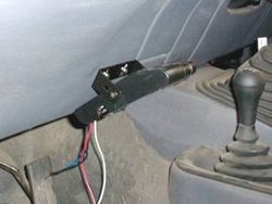
Brake Controller Installation: Starting from Scratch ...

3028 --- Tekonsha & Draw-Tite Brake Control Dual Plug Wiring Harness
Honda Ridgeline Brake Controller Installation Instructions
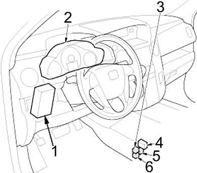
Honda Pilot (2009 - 2015) - fuse box diagram - Auto Genius

2003 Honda Pilot. Brake Lamp dash indicator just came on ...
Brake Control Reliance
trailer brake controller plug-in location??? | Honda Pilot ...
14-18 Silverado Sierra Brake Control adapter $17 free shipp ...

Tekonsha | 1 - Plug Adapters
0 Response to "38 pilot brake controller wiring diagram"
Post a Comment