37 omron relay wiring diagram
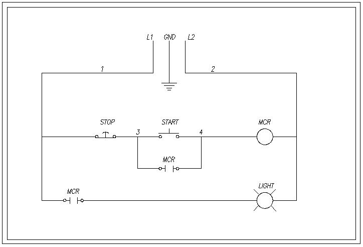
Oct 01, 2019 · Question: Need wiring diagram from mach3 USB breakout board to inverter. Current Solution. I suppose you are trying to determine how to connect the VFD.Jan 03, · The relay on the breakout board is a pass-through switch with NO, COM and NC connections. Answer each of these questions by expanding upon the diagram shown above: draw the components necessary to show a complete electrical circuit (i.e. details of the power source), as well as an additional rung (or two) showing a relay coil actuated by some sort of switch contact, and the relay contact controlling power to a second indicator lamp.
Oct 18, 2019 · wiring diagram for auto relay wiring diagram article. Architectural wiring diagrams be active the approximate locations and interconnections of receptacles, lighting, and enduring electrical facilities in a building. Interconnecting wire routes may be shown approximately, where particular receptacles or fixtures must be upon a common circuit.

Omron relay wiring diagram
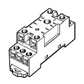
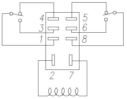
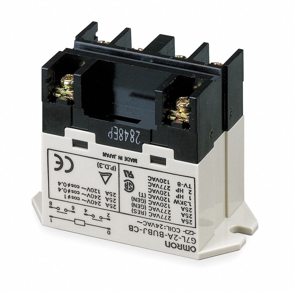
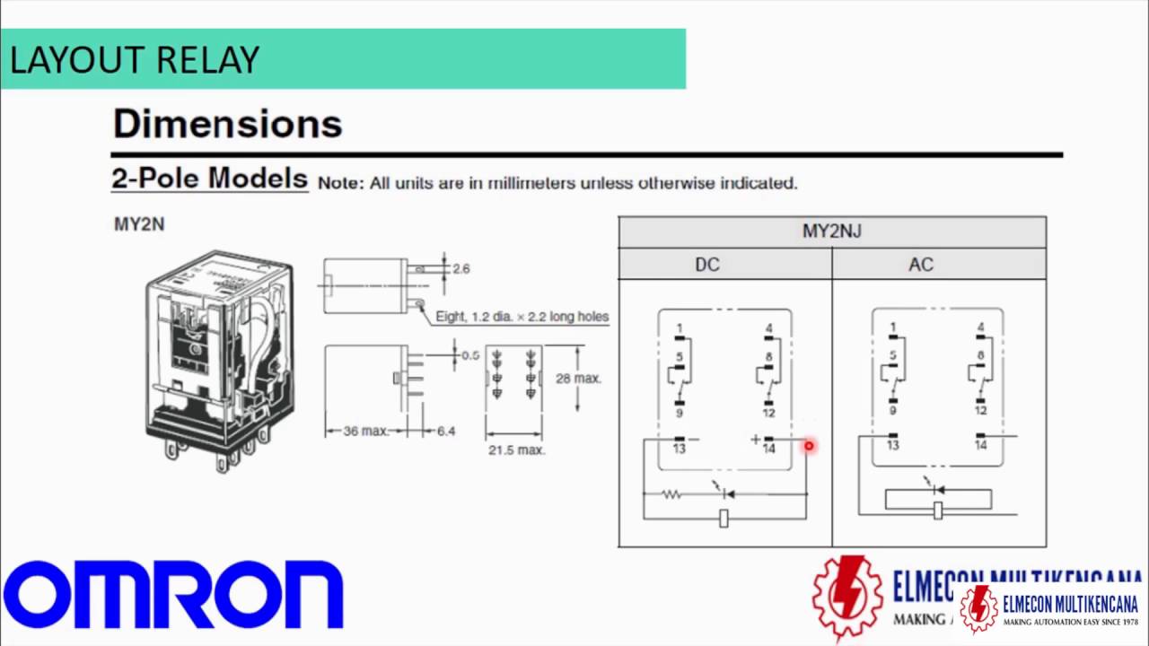
Note 3 Default relay N.O./N.C. Page 193 Wire size for control and relay terminals Use wires within the specifications listed below. For safe wiring and reliability, it is recommended to use ferrules, but if solid or stranded wire is used, strip- ping length should be 8 mm. Oct 17, 2019 · These relay diagrams focus on the wiring configuration in a 2-pole relay circuit. One is the square, and the other one is round, but their functioning is similar to each other. The coil wire will connect to pin 2 and pin seven on the socket for the wiring. Mar 23, 2020 · A Control Relay is also known as a Relay, is a switch, an electromagnetic switch. A control relay allows electrical current to flow through a conducting coil that opens or closes a switch. It also protects the circuit current. With a control relay, users do not need to manually turn the switch to isolate or change the state of an electric circuit.
Omron relay wiring diagram. View and Download Omron H5CR series manual online. Multifunction Digital Timer. H5CR series timer pdf manual download. Also for: H5cr-s, H5cr-b, H5cr-l, H5cr-ss, H5cr-bs, H5cr-ls. Mar 23, 2020 · A Control Relay is also known as a Relay, is a switch, an electromagnetic switch. A control relay allows electrical current to flow through a conducting coil that opens or closes a switch. It also protects the circuit current. With a control relay, users do not need to manually turn the switch to isolate or change the state of an electric circuit. Oct 17, 2019 · These relay diagrams focus on the wiring configuration in a 2-pole relay circuit. One is the square, and the other one is round, but their functioning is similar to each other. The coil wire will connect to pin 2 and pin seven on the socket for the wiring. Note 3 Default relay N.O./N.C. Page 193 Wire size for control and relay terminals Use wires within the specifications listed below. For safe wiring and reliability, it is recommended to use ferrules, but if solid or stranded wire is used, strip- ping length should be 8 mm.
Original And Brand New Omron Relay My2n-gs Dc24v Large In ...
Overview of General Purpose Relays | OMRON Industrial Automation
OMRON MY4N DC24 Power Relay, 4PDT, 24 VDC, 5 A, MY Series, Socket, Non Latching

What is a relay, its function, types and relay wiring - Updated!

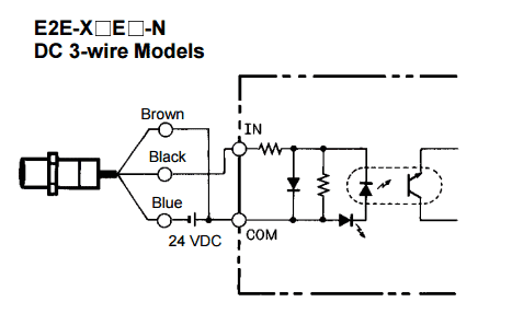
H3CR Timer: Wiring Power Supply and Input Devices | FAQ ...
MY-GS Miniature Power Relays/Dimensions | OMRON Industrial ...
Low Voltage Switching Gears

Omron LY2 12 VDC 8 Pin Relay Wiring? - CR4 Discussion Thread

GEYA NG2R 6 Channel Omron Relay Module 5V 12V 24V 230V Relay ...
Wiring Interposing Relays - NPN PNP Isolation | Acc Automation
DIY ATO help | REEF2REEF Saltwater and Reef Aquarium Forum

Omrn Relay my2n intrelocking # My2n relay wiring diagram ...

OMRON MY2N Relay Connection in Hindi (Practical)
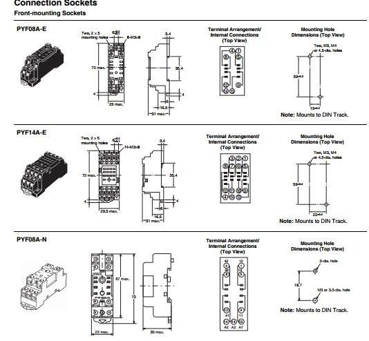
PTF14A-E
NEW ORIGINAL MY4N-GS 220/240VAC and 24VDC OMRON Intermediate ...
Spdt relay | Terry Love Plumbing Advice & Remodel DIY ...
PYF08A-N Omron Automation and Safety | Mouser

OMRON MY-GS Miniature Power Relays/Features General Purpose ...

Page top OMRON Industrial Automation Global Global ...
Safety Precautions of General Purpose Relays Cautions for ...
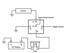
How To Wire A Relay

How to wire H3CR timer

omron relay wiring diagram, omron relay wiring diagram ...
How To Wire A Relay
100/120V AC, 6-Pin Bottom Flange Enclosed Power Relay; Electrical Connection: Screw
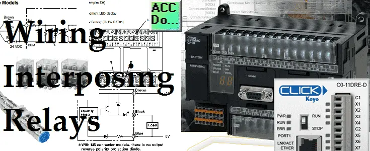
Wiring Interposing Relays - NPN PNP Isolation | Acc Automation
How to replace plug-in type relay with correct orintation ...

What is a relay, its function, types and relay wiring - Updated!

Relay Wiring With AC Load II OMRON MY2N-MY4N Relay Wiring/Connection
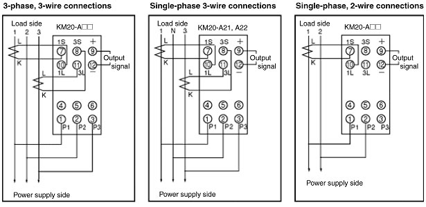
FAQ01729 for Measuring / Motor Protective Relays | OMRON ...
Overview of General Purpose Relays | OMRON Industrial Automation

MY2N-GS 24VDC OMRON - Relay: electromagnetic | DPDT; Ucoil ...

MY2 AC110/120 (S)
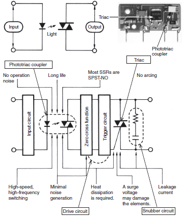
Overview of Solid-state Relays | OMRON Industrial Automation
TUTORIAL RELAY OMRON
Further Information of Solid-state Relays | OMRON Industrial ...

1NO1NC Omron Plug in Relay Module FY-NG2R
0 Response to "37 omron relay wiring diagram"
Post a Comment