37 6.2 glow plug controller wiring diagram
It will not make a difference whether the glow plug controller (2920-01-175-7214) or the temp sensor (2920-01-469-6903) is installed in the water cross over pipe. ... One or more of the glow plugs are bad; Wire(s) disconnected or damaged Glow plug wires; Power wires; ... I found this pin testing diagram that one HMMWV owner posted in a HMMWV ... Check the glow plugs. Most 6.2 L diesels came with one relay but early models had two. Test the glow plugs by unplugging the electrical connection from a glow plug. Hook up an ohmmeter to the glow plug terminal and ground the other end. The resistance should read between 0.8 and 2 ohms, depending on the glow plug type.
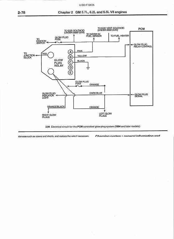
a 1984 chev k-10 6.2 diesel that has no glow plug function..wiring i have a 1984 chev k-10 6.2 diesel that has no glow plug function. i need the wiring schematics for the entire glow plug circuitry. this is the old style round controller that screws into the l.r. cyl …

6.2 glow plug controller wiring diagram
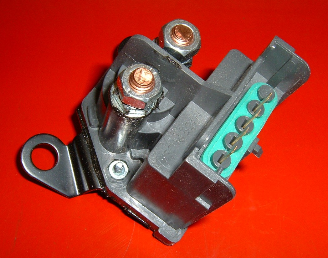
A glow plug relay, or other standard relay, will have an isolated ground, with a 12V signal and a ground lug. Usually the control is from the ground lug, while the supply is either keyed hot, or always hot. Oh, and any relay that is for a starter relay, is not designed for constant current, even if it's wired correctly. The Glow Plug Relay - Located on the left inner fender panel, provides current to the glow plugs as long as the thermal controller completes the ground circuit. The 6 Volt Glow Plugs--Used in This 12 Volt System - Are pulsed ON and OFF by the glow plug relay in response to messages received by the controller to prevent damage to the glow plugs. We also carry glow plugs, glow plug relays, and glow plug kits for your early 6.2L engine. Fits 1982 -1984 6.2 Diesel. Problems can be solved much more easily when civility is kept intact. In most cases, we do not generate application lists.
6.2 glow plug controller wiring diagram. 28/12/2016 · GMC Sierra mk1 (2005) – fuse box diagram. Year of production: 2005. Instrument Panel Fuse Block. The fuse block access door is on the driver’s side edge of the instrument panel. 1983 K5 6.2L, i have all the Diesel Page books and bought the new controller + plug. But in the book it says to install the controller on the DS fender for a warm climate. I live in Toronto Canada so I dont have any issues with warm starting just when its dead cold out. In the book it says that the factory location was on the firewall above the motor, does that location work best? Title: Glow Plug Wiring Diagram 6 9 Author: OpenSource Subject: Glow Plug Wiring Diagram 6 9 Keywords: glow plug wiring diagram 6 9, diesel glow plug wiring harness o reilly auto parts, glow plug wiring diagram 6 9 bagsluxumall com, 6 0l glow plug wiring diagram wiring diagram pictures, vincewaldon com how to pimp your glowplug wiring, 6 9 litre international glow plug controller wiring ... 6.2 wiring diagram for electronic controller glow plug relay system, Jump to Latest Follow 1 - 3 of 3 Posts. Riddle_3d · Registered. Joined Sep ... the glow plug controller is usually in the rear top of the passenger head, the fast idle/cold advance is usuall in the rear, side of the passenger head, and on some of the newer ones it moved to ...
Click to get the latest Buzzing content. Sign up for your weekly dose of feel-good entertainment and movie content! Wiring Diagrams 6.2 Glow Plug Controller Wiring Diagram [Archive] Glow System Contoller Location L Diesel. In your M the glow plug controller normally is located in a black box under For the wiring diagrams you should look at TM or TM I have an 86 Chevy Diesel with a L engine. The negative side of the glow plug relay (distributor) will not engage. 1983 glow plug relay wiring diagram for 6.2L Diesel. Posted by Anonymous on Jun 24, 2012. ... I have a '98 Jetta diesel that had problems with the glow plug circuit. I ended up replacing the harness and a fuse. All the information I needed to know I found on this web page: Cat5E Plug Wiring Diagram from s-media-cache-ak0.pinimg.com Print the wiring diagram off plus use highlighters to trace the signal. When you make use of your finger or perhaps the actual circuit with your eyes, it is easy to mistrace the circuit. 1 trick that We 2 to printing a similar wiring plan off twice.
Latest information about coronavirus (COVID-19), online services and MyAccount, customer services and how to make a complaint. I recommend replacing every time to plugs are replaced as preventative maintenance or every 100K miles. Also fits 85-92 6.2's. Notes: Replacement harness is available as p/n ssd-1871. With the use of harness ssd-1871 you can use the ssd-1005 controller on any vehicle as an automatic controller. Wiring diagram available upon request. Club Car Precedent Wiring Diagram 48 Volt; Honeywell Thermostat Th9421c1004 Wiring Diagram If You Only Have 2 Wires; Crestron Light Switch Wiring Diagram; Asco Redhat 2 Wiring Diagram; 6.2 Glow Plug Controller Wiring Diagram; Fleetmatics Wiring Diagram; Onan 4500 Comercial Generator Wiring Diagram; Omc 7.5l Distributor Wiring Diagram; Recent ... Super Moderator. Steel Soldiers Supporter. 13,804. 161. 63. Location. OKC, OK. The easiest way to work on a CUCV electrical issue is to copy and paste the wiring diagram you need from the TM, save it to your computer, And then color the circuit you are working on. I use MS Paint.
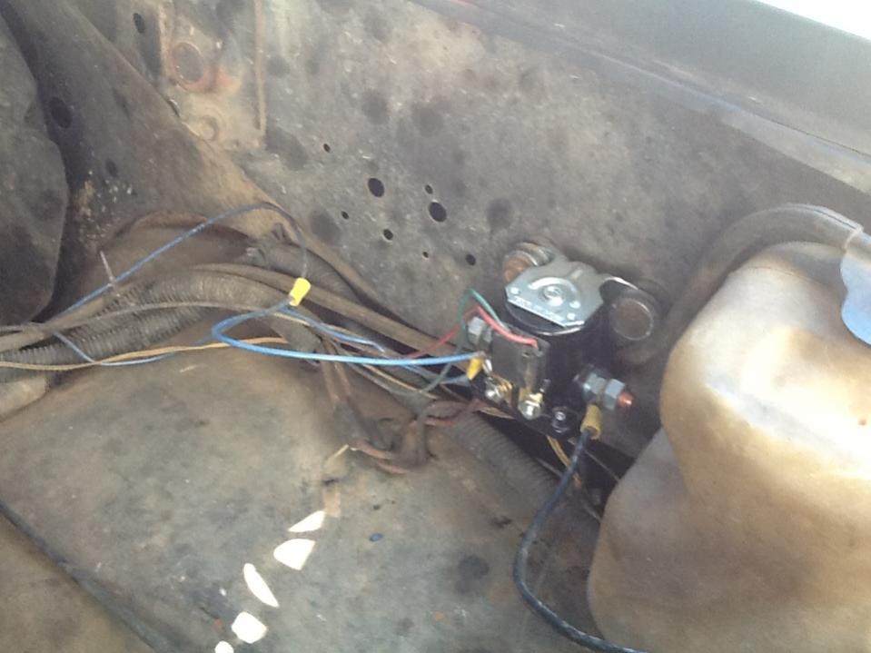
2. Ran a wire from each side of the two main screw terminals (which are toward the front on the glow plug relay) to the terminals of the solenoid/relay. 3. Ran a wire from the solenoid/relay's controlling terminal to a lighted switch under the dashboard that goes to a positive lead from the lighter.
10.09.2018. 10.09.2018. 0 Comments. on 6.2 Glow Plug Controller Wiring Diagram. Check that the four-wire connector at the controller is seated properly and latched . Tighten the 1: Glow plug system schematic, (L). Click image to see. [IMG] Does anyone have a pinout for the glow plug controller? links on their website that you can download ...
Joined Mar 13, 2008. ·. 3,949 Posts. #5 · Dec 11, 2009. on the drivers side there should be a wire on the front and rear glowplug and a rail from the front across each of them to the rear. on the pass side i cant be sure if there is two wires or not. but there should be a wire and then the rail across the plugs. U.
Page 214: Glow Plug 12. Electrical System 12.8 Glow plug A glow plug is available for warming intake air when starting in cold areas in winter. The glow plug is M4 x 0.7 mounted to the cylinder head. The device is operated by the glow switch on the instrument panel. Rated current 8-10A Rated voltage... Page 215: Electric Engine Stopping Device 12.
Page 169 2-Valve Cylinder Head ENGINE Removal of Valve Cover Removing the glow plugs 1. Remove the valve cover nuts (Figure 6-7, (1)). 1. Remove the glow plug harness (Figure 6-6, (2)) from each glow plug 2. Remove the O-ring (Figure 6-7, (2)) on each (Figure 6-6, (1)). Page 170 ENGINE 2-Valve Cylinder Head Removal of Rocker Arm Assembly 1 ...
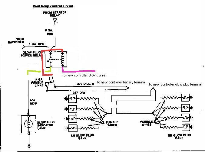
My own design for a glow controller for my 1988 Late style factory glow controller.
This is to me the best way to run your glow plugs for your GM 6.2 or 6.5 diesel engine. She fires right up every time and it allows you to control how long ...
The glow plug control unit uses a glow plug relay to switch the current for the glow plugs on and off. The more glow plugs monitored by a control unit, the higher the current the circuit will need. To reduce the current needed, glow plugs are often distributed across two circuits, with two glow plug relays.
· 0 Comments on Glow Plug Controller Wiring Diagram Check that the four-wire connector at the controller is seated properly and latched. Tighten the 1: Glow plug system schematic, (L). Save diesel glow plug controller to get e-mail alerts and updates on your eBay Feed. + Items in search results. See search results that fit your vehicle.
07 Isuzu Npr 6.0 Tac Wiring Diagram; 4l80e Neutral Safety Switch Wiring Diagram; Wiring Diagram Realistic Model 12-1954; Cat Xq75 Generator Wiring Diagram; Wiring Diagram For A Scandia Sauna; 6.2 Glow Plug Controller Wiring Diagram; Toc Dodge Durango Wiring Diagram; Ford Fleet 2008 Pto Wiring Diagram; Speakercraft 3.5mm Wiring Diagram; Recent ...
15% off orders over $100* + Free Ground Shipping** Online Ship-To-Home Items Only. Use Code: DEALS4JAN
Enter the email address you signed up with and we'll email you a reset link.
Dec 26, 2012 — The one piece glow plug controller of 85+ on the 6.2 was actually a very simple unit. Here's a wiring diagram of how the controller is wired ...5 posts · I am new at this so cut me some slack. I have an 85 6.2l diesel and the glow plugs wont ...
GM 6.2L / 6.5L Glow Plug Controller Made in the USA This 6.2/6.5 diesel glow plug controller fits all 1985 to 1993 6.2 GM diesels as well as 1992 to 1993 6.5. Also fits heavy duty 6.5L applications 1994 and later with mechanical injection pumps only. (Pickup and light Van applications 1994 and later will use the 6.5L controller - see our website.)
3.Terminal C connects to the light blue wire from terminal 3 of the old glow plug controller that has been connected the two black wires from terminal 5 and 6 of the old glow plug controller. 4.Terminal D connects to the main wiring harness and receives power when the ignition switch is in the ON position. 5.Terminal E is grounded to the chassis.
FYI The glow plugs have been changed with no success to the problem. The connector, 4-wire to the glow plug controller, 3 wires are hot and working. The wire which goes to the inhibit temp switch from the controller seems fine to the switch. After the switch, the green wire seems to be grounded or shorted.
We also carry glow plugs, glow plug relays, and glow plug kits for your early 6.2L engine. Fits 1982 -1984 6.2 Diesel. Problems can be solved much more easily when civility is kept intact. In most cases, we do not generate application lists.
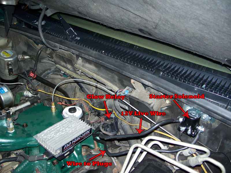
The Glow Plug Relay - Located on the left inner fender panel, provides current to the glow plugs as long as the thermal controller completes the ground circuit. The 6 Volt Glow Plugs--Used in This 12 Volt System - Are pulsed ON and OFF by the glow plug relay in response to messages received by the controller to prevent damage to the glow plugs.
A glow plug relay, or other standard relay, will have an isolated ground, with a 12V signal and a ground lug. Usually the control is from the ground lug, while the supply is either keyed hot, or always hot. Oh, and any relay that is for a starter relay, is not designed for constant current, even if it's wired correctly.









0 Response to "37 6.2 glow plug controller wiring diagram"
Post a Comment