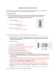
40 the diagram at right shows a copper wire loop held in place
poles(Lenze's law) . The magnetic poles of the induced current loop are also shown in the diagram . The net magnetic force on the loops is to the right. 34.3 Yes. As the loop falls the magnetic flux linked with the loop decreases hence there is an induced current in the loop in the direction shown in the diagram. The current in the wire produces a magnetic field. At point 1 this external field is OUT of the page. At point 2 the external field is INTO the page. This magnetic field passes through the loop and is the source of magnetic flux through the coil. As the loop slides by position 1, the flux through the loop is INCREASING and it is Pointing
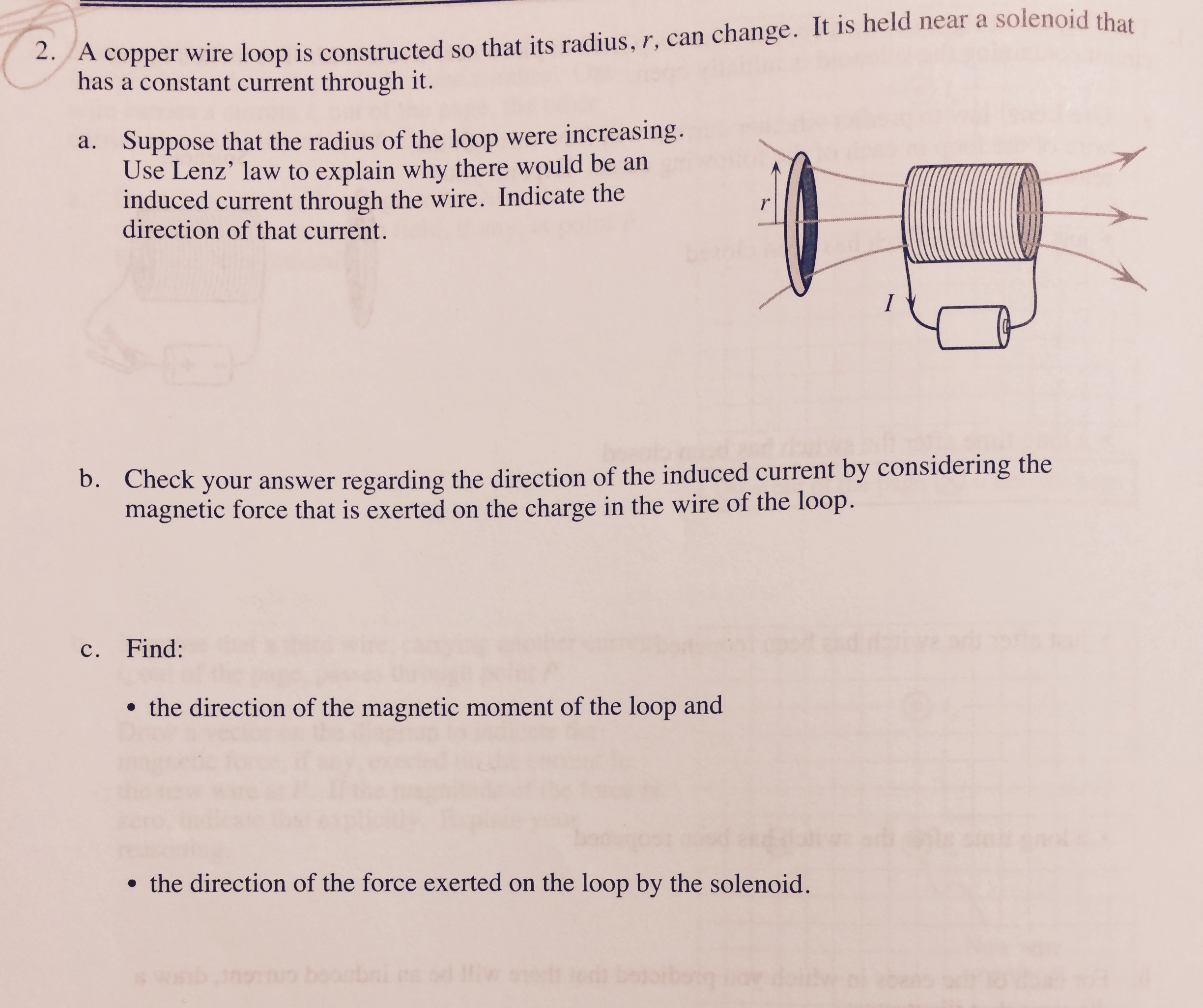
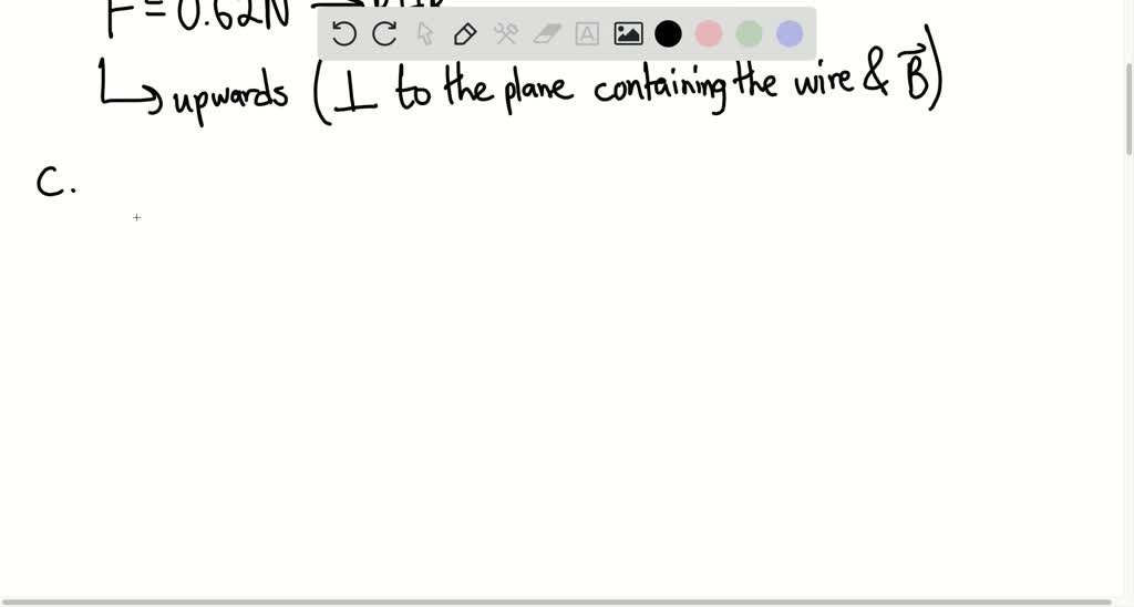
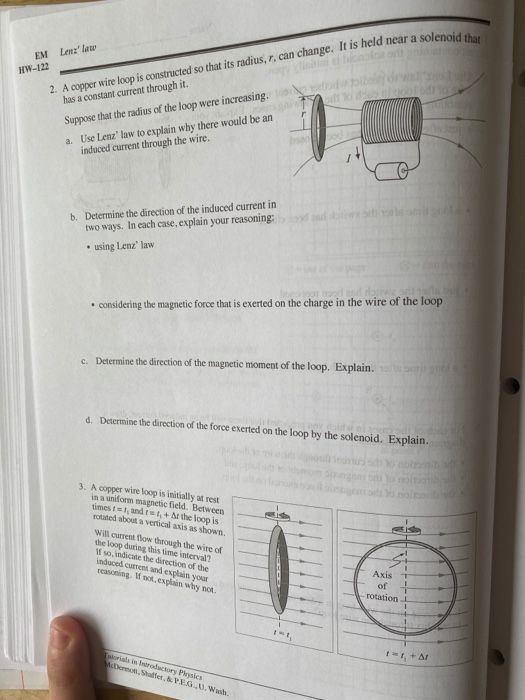
A loop is pulled with a force F to the right to maintain a constant speed of 8.0 m/s. The loop has a length of 0.15 m, a width of 0.080 m, and a resistance of 200.0 Ω. At the instant shown, the loop is partially in and partially out of a uniform magnetic field that is directed into the paper. The magnitude of the field is 1.2 T. 61.
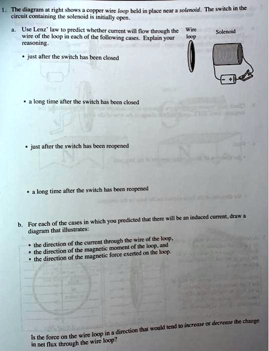
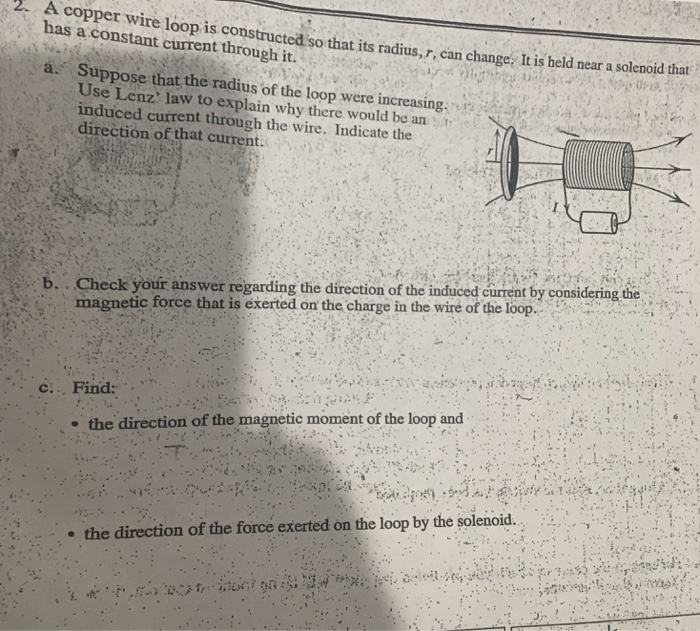
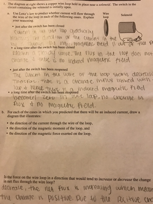
The diagram at right shows a copper wire loop held in place
The diagram shows a rigidly-clamped straight horizontal current-carrying wire held mid-way between the poles of a magnet on a top-pan balance. The wire is perpendicular to the magnetic field direction. The balance, which was zeroed before the switch was closed, read 161 g after the switch was closed. A pattern of concentric circles indicating the field lines of a magnetic field around a straight conducting wire. The arrow shows the direction of the field lines. Close the key so that a current flows through the wire. Ensure that the copper wire placed between the points X and Y remains vertically straight. Gently tap the cardboard a few times. 27. In the diagram at the right, electron current is passed through a solenoid. The north pole of the solenoid is nearest to point (1) A (3) C (2) B (4) D 28. The diagram below shows an electron current in a wire loop. What is the direction of the magnetic field at the center of the loop? (1) out of the page (3) clockwise (2) into the page (4 ...
The diagram at right shows a copper wire loop held in place. Transcribed image text: 1. The diagram at right shows a copper wire loop held in place near a solenoid. The switch in the circuit containing the solenoid is initially open. a. Use Lenz' law to predict whether current will flow through the Wire Solenoid wire of the loop in each of the following cases. The diagram at right shows a copper wire loop held in place near a solenoid. The switch in the circuit containing the solenoid is initially open. Wire Solenoid a. Use Lenz's law to predict whether current will flow through the wire of the loop in each of the following cases. The diagram at right shows a copper wire loop held in place near a solenoid. The switch in the circuit containing the solenoid is initially open. Use Lenz' law to predict whether current will flow through the wire of the loop in each of the following cases. Explain your reasoning. just after the switch has been closed a long time after the ... Moving a length of copper wire through a magnetic eld may cause the wire to have a A. potential di erence across it ... A resistor was held at constant temperature in an operating electric circuit. A student measured the current through ... The accompanying diagram shows two resistors connected in series to a 20.-volt battery.
A circular loop of wire is held in a uniform magnetic field, with ... place your loop so that the transmission cable passes through your loop (b) simply place your loop near the transmission cable ... The figure below shows a circular loop of wire being dropped toward a wire carrying a current to the left. The A copper wire loop is held in place near a solenoid. The switch in the circuit containing the solenoid is initially open. a. Use Lenz's law to predict whether the current will flow through the ... The 12-gauge wire has a diameter of 1/12 inch while the 14-gauge wire has a diameter of 1/14 inch. Thus, 12-gauge wire has a wider cross section than 14-gauge wire. A 20-Amp circuit used for wall receptacles should be wired using 12-gauge wire and a 15-Amp circuit used for lighting and fan circuits should be wired using 14-gauge wire. Lenz's Law. The direction of the induced emf drives current around a wire loop to always oppose the change in magnetic flux that causes the emf. Lenz's law can also be considered in terms of conservation of energy. If pushing a magnet into a coil causes current, the energy in that current must have come from somewhere.
FIGURE Q33.8 shows a bar magnet, a coil of wire, and a current meter. Is the current through the meter right to left, left to right, or zero for the following circumstances? Explain. a. The magnet is inserted into the coil. b. The magnet is held at rest inside the coil. c. The magnet is withdrawn from the left side of the coil. Problem: The diagram at right shows a copper wire loop held in place near a solenoid. The switch is the circuit containing the solenoid is initially open.a.1 answer · Top answer: Lenz's law of electromagnetism states that an induced electric current flows in a direction such that the current opposes the change that induced it. ... Identical copper wire loops are placed in different external magnetic fields, ... A. The diagram at right shows a stationary copper wire loop in a uniform.8 pages Take a long straight copper wire, two or three cells of 1.5 V each, and a plug key. Connect all of them in series as shown in Fig. 5 (a). Place the straight wire parallel to and over a compass needle. Plug the key in the circuit. Observe the direction of deflection of the north pole of the needle.
b) Move a metal loop away from a current carrying wire. c) Drop an iron sheet through a region with a constant magnetic field. d) Hold a copper loop next to a current carrying wire. e) All of the above choices result in an induced current. 30.4.3. An ammeter is connected to a coil of wire. A magnet is sitting
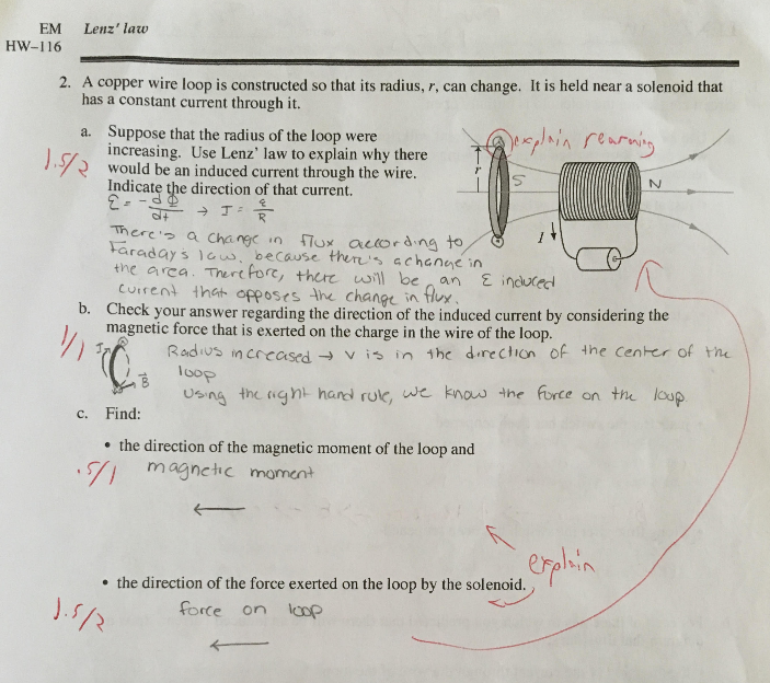
Problem 1 (13 points) The diagram shows a copper wire loop held in place near a solenoid. The switch in the circuit containing the solenoid is initially open. a. Use Lenz's law to predict whether current will flow through the wire of the loop in each of the following cases.
The diagram a1 right shows copper wirc loop held in place ncar & solcnoid. The switch in the cinuit containing the solenoid initially open.4 answers · Top answer: Hi. I'm the given problem here. This is a circuit having a resistance, Marcel And a switch ...

Physics. Physics questions and answers. HW-107 1. The diagram at right shows a copper wire loop held in place near a solenoid. The switch in the circuit containing the solenoid is initially open a. Use Lenz" law to predict whether current will flow through the Wire wire of the loop in each of the following cases. Explain your loop reasoning.
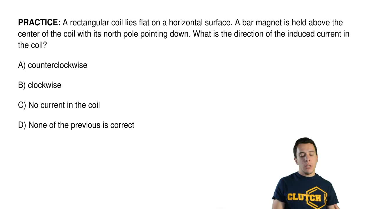
ÎWire #1 (length L) forms a one-turn loop, and a bar magnet is dropped through. Wire #2 (length 2L) forms a two-turn loop, and the same magnet is dropped through. Compare the magnitude of the induced currents in these two cases. (a) I 1 = 2 I 2 (b) I 2 = 2 I 1 (c) I 1 = I 2 ≠ 0 (d) I 1 = I 2 = 0 (e) Depends on the strength of the magnetic field

To complete its circuit, the current must flow to the left in the top conductor, down through the resistor, and to the right in the bottom conductor. This means a counterclockwise current throughout the entire circuit. Q7 A large circular loop of wire lies in the horizontal plane. A bar magnet is dropped through the loop.
A proton and an electron are held in place on the x axis. The proton is at x = -d, while the electron is at x = +d. They are released simultaneously, and the only force that affects their motions significantly is the electrostatic force of attraction that each applies to the other.

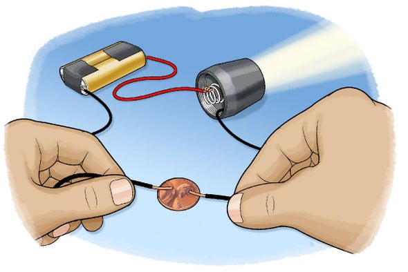
Compare the arrangement of the cell, bulb and wire at the right to the unsuccessful arrangements shown above. In attempt A, the wire does not loop back to the negative terminal of the cell. In attempt B, the wire does form a loop but not back to the negative terminal of the cell. In attempt C, there is no complete loop at all.
Homework Statement. You have 2 magnets separated by a distance. The top magnet has its south end facing the north end of the other magnet thus forming a magnetic field. Finally you insert a loop of copper wire (the pic shows a copper tube though) between the two magnets with the open ends perpendicular to the surfaces of the magnets.
A copper hoop is held in a vertical east-west plane in a uniform magnetic field whose field lines ... The diagram shows a circular loop of wire that rotates at a steady rate about a diameter O ... A merry-go-round has an area of 300m2 and spins at 2rpm about a vertical axis at a place where Earth's magnetic field is vertical and has a ...

Three point charges are held fixed in place as shown. ... The diagram at right shows a copper wire loop held in place near a solenoid.
wire is A. Parallel to the wire. B. Inside the wire. C. Perpendicular to the wire. D. Around the wire. ... copper (a penny), aluminum, glass, and plastic, experience no force from a magnet. ... The right-hand rule determines the orientation of the compass needles to the direction of the current.

Show with the aid of the diagram how a wire is wound on a U-shaped piece of soft iron in order to make it an electromagnet. Complete the circuit diagram and label the poles of the electromagnet. ... A current is started in a wire held near a loop of wire. (2)The current is stopped in a wire held near a loop of wire. ... Primary and secondary ...
Wire loop a. Solenoid just after the switch has been closecd .a long time; Question: I. The diagram at right shows a copper wire loop held in place near a solenoid. The switch in the circuit containing the solenoid is initially open. Use Lenz' law to predict whether current will flow throughthe wire of the loop in each of the following cases.

D. C. Upadhyay, , Er. Meera Goyal, Dr. J. P. Goel, · 20163 (a) Show, with the help of a diagram, how unpolarised sunlight gets polarised due ... A conducting loop is held below a current carrying wire PQ as shown.

27. In the diagram at the right, electron current is passed through a solenoid. The north pole of the solenoid is nearest to point (1) A (3) C (2) B (4) D 28. The diagram below shows an electron current in a wire loop. What is the direction of the magnetic field at the center of the loop? (1) out of the page (3) clockwise (2) into the page (4 ...

A pattern of concentric circles indicating the field lines of a magnetic field around a straight conducting wire. The arrow shows the direction of the field lines. Close the key so that a current flows through the wire. Ensure that the copper wire placed between the points X and Y remains vertically straight. Gently tap the cardboard a few times.

The diagram shows a rigidly-clamped straight horizontal current-carrying wire held mid-way between the poles of a magnet on a top-pan balance. The wire is perpendicular to the magnetic field direction. The balance, which was zeroed before the switch was closed, read 161 g after the switch was closed.
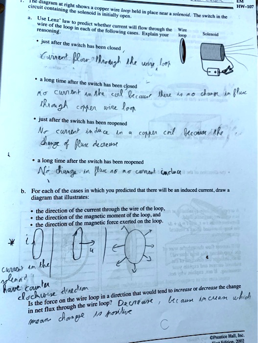
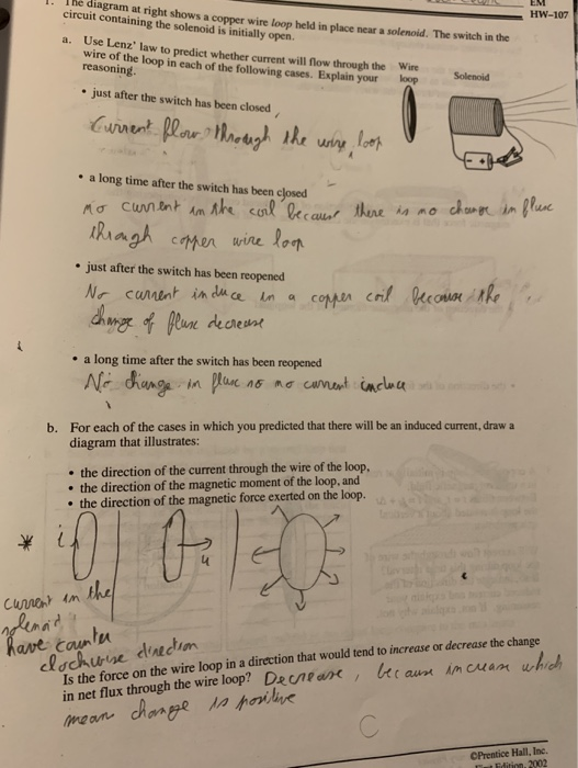


0 Response to "40 the diagram at right shows a copper wire loop held in place"
Post a Comment