37 block diagram to state space
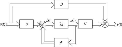
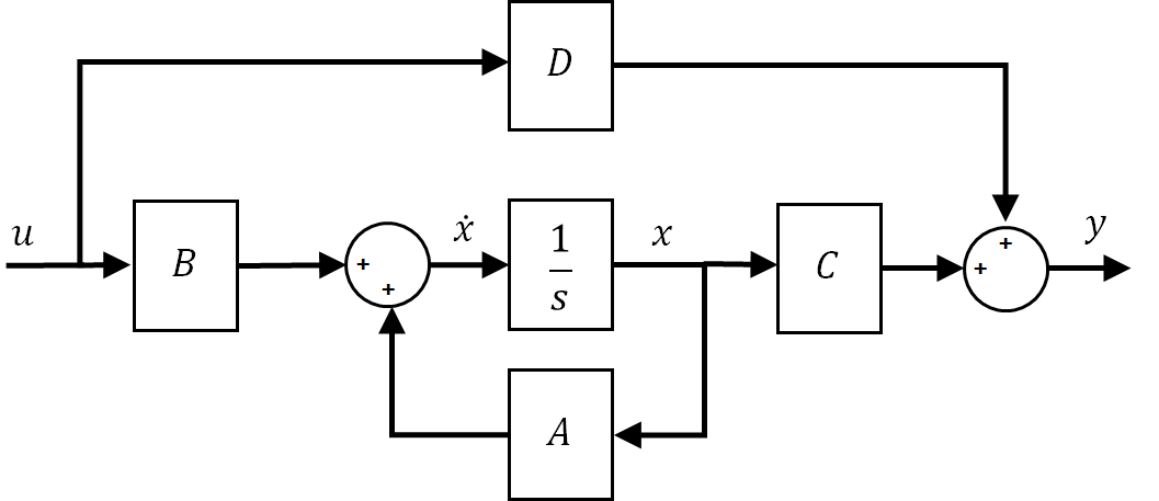
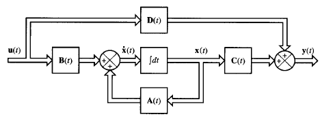
PDF Transfer Functions and State Space Blocks In particular, we might only want to output the solution component x2. So, we let C = [0,1] and D = 0. The block diagram for this process is shown in Figure 4.1. uB1 sC D A ++ + ˙x+ input y output Figure 4.1: State space representation of the systemx0= Ax+ Bu,y= Cx+ Du, The whole process is captured in theState Space Block. Control System I EE 411 State Space Analysis Draw a direct form realization of a block diagram, and write the state equations in phase variable form, for a system with the differential equation Solution we define state variables as x 1=y, x 2 =y&,and x 3=y&&+13 u, ١٦ then the state space representation is
Implement linear state-space system - Simulink Description The State-Space block implements a system whose behavior you define as where x is the state vector, u is the input vector, y is the output vector, and x 0 is the initial condition of the state vector. The A, B, C, and D matrices can be specified as either sparse matrices or dense matrices.
Block diagram to state space
Differential Equation - State Space | ShareTechnote The first thing you may try is to connect the same variable x as shown below. But this is not correct since a connection line is not allowed to have the arrow head on both sides. Then, let's add a integration block to x' and you would have following diagram. Now you see three same variable that are not connected. PDF LECTURE 1 - Princeton University plex diagrams. The general procedure to obtain the final state-space system remains. same: Stack the states of all subsystems in a tall vector. x and compute ˙ using the state and output equations of the individual blocks. SYSTEM DECOMPOSITION. Block diagrams are also useful to represent complex systems as the interconnection simple blocks. LabVIEW Block Diagram Explained - NI 04.02.2020 · In this introduction to the Block Diagram, we examine the concept of this tool as well as the Block Diagram’s relationship with the Front Panel. We also explore how to open the Block Diagram, how to find objects in the Functions palette and put them on the Block Diagram, and how to use different toolbar icons. In addition, we learn how to build a simple block …
Block diagram to state space. PDF 2.14AnalysisandDesignofFeedbackControlSystems State ... In state-determined systems, the state variables may always be taken as the outputs of integrator blocks. A system of order n has n integrators in its block diagram. PDF Using the State-Space and Transfer Function Blocks in Simulink State-Space block from the Continuous sub-menu of the Simulink library. Complete the model with the Step and Scope blocks as shown in Fig. 1. Fig. 1. Basic system model using the State-Space block. At this point the model is very general, and an equation of any order can be set up for solution in the block parameters. The equation inside the ... Control Systems - State Space Model - Tutorialspoint Basic Concepts of State Space Model. The following basic terminology involved in this chapter. State. It is a group of variables, which summarizes the history of the system in order to predict the future values (outputs). State Variable. The number of the state variables required is equal to the number of the storage elements present in the system. Mass Spring Damper System - Cookie Robotics Block Diagram State Space Model. When there is a mass in a system, its position and velocity are commonly chosen as state variables. Also, position, velocity, and force (input) are sufficient to determine this system's future position (output).
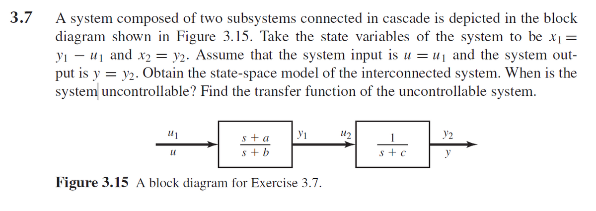
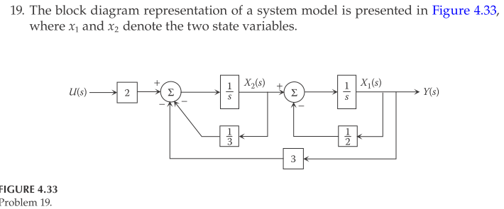
PDF EXAMPLE PROBLEMS AND SOLUTIONS - SUTech Thus, a state-space model of the system in the standard form is given by It is important to note that this is not the only state-space representation of the system. Many other state-space representations are possible. However, the number of state variables is the same ... block diagram efining state lriables for the stem. Rewriting gives SysML Example Tutorial: Griffin Space Vehicle Project This SysML Example Tutorial features a hypothetical Griffin Space Vehicle Project example to illustrate best practices for specifying System-of-System (SoS) complexity using the Systems Modeling Language (SysML). This SysML example applies the MBSE + SysML System Architecture Framework Pattern, and llustrates numerous recursive MBSE Analysis and … How to get state-space equations form from a block diagram? 1 This is the block diagram that I'd like to transform into a state-space representation, where u1 and u2 are inputs and y1 and y2 are the outputs of the system I tried to place state variables on the diagram and go from there (is there a cleaner way to do this?): I am not sure how to go about from here. The 1 s + 1 block is confusing me. Regulated Power Supply-Block Diagram,Circuit Diagram,Working 13.08.2018 · Source/Line Regulation – In the block diagram, the input line voltage has a nominal value of 230 Volts but in practice, here are considerable variations in ac supply mains voltage. Since this ac supply mains voltage is the input to the ordinary power supply, the filtered output of the bridge rectifier is almost directly proportional to the ac mains voltage.
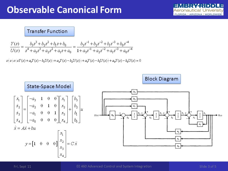
How to get the state-space model of a dynamic system - x ... Image: State-space model Xcos block diagram - mechanical system position response csim() As you can see, we have the same response as for the Xcos block diagram model, the only difference being that the unitary step time is 0 s for the Scilab model and 0.1 s for the Xcos model. PDF 3.1 State Space Models - Rutgers University The block diagram for this decomposition is given in Figure 3.1. U(s) V(s) V(s)/U(s) Y(s)/V(s) Y(s) Figure 3.1: Block diagram representation for (3.17) Equation (3.17a) has the same structure as (3.6), after the Laplace transformation is applied, which directly produces the state space system equation identical to (3.9). It remains to find ... control theory - how to obtain state space diagram and ... How do we obtain a state-space realization and a block diagram of a given transfer function? Consider the transfer function $$\\frac{C(s)}{R(s)}=\\frac{5s}{3s^{2}+3s+1}$$ Steps for solution are $... Transfer Function ↔ State Space - Swarthmore College To see how this method of generating a state space model works, consider the third order differential transfer function: We start by multiplying by Z (s)/Z (s) and then solving for Y (s) and U (s) in terms of Z (s). We also convert back to a differential equation. We can now choose z and its first two derivatives as our state variables
Communication Systems - Block Diagram, Types, Elements ... Block Diagram of Communication Systems; Objective Questions . Types Of Communication Systems. Depending on Signal specification or technology, the communication system is classified as follows: (1) Analog . Analog technology communicates data as electronic signals of varying frequency or amplitude.
Block diagram representation of the state space equations. It deals with the mechanical system with two degrees of freedom. State-Space block solution is compared with solution made by an alternative approach, using so ...
Solved Derive the state-space representation of the ... Derive the state-space representation of the function given below and draw the block diagram according to the state-space representation. Set the initial states to zero. Derive the state-space representation of the function given below and draw the block diagram according to the state-space representation. Set the initial states to zero.
Introduction: State-Space Methods for Controller Design The equations in the block diagram above are given for the estimate . It is conventional to write the combined equations for the system plus observer using the original state equations plus the estimation error: . We use the estimated state for feedback, , since not all state variables are necessarily measured.
State-space representation - Wikipedia In control engineering, a state-space representation is a mathematical model of a physical system as a set of input, output and state variables related by first-order differential equations or difference equations.State variables are variables whose values evolve over time in a way that depends on the values they have at any given time and on the externally imposed values of input variables.
Block Diagram Maker | Block Diagram Software | Creately Begin by opening a Creately workspace, you can make edits to multiple pre-made templates or start creating your block diagram from scratch. Identify all the components, inputs, and outputs within your system. Use the purpose built shape library and simply drag-and-drop symbols and notations onto your canvas.
bloc2ss - Block-diagram to state-space conversion block-diagram to state-space conversion Calling Sequence [sl]=bloc2ss(blocd) Arguments blocd list sl list Description Given a block-diagram representation of a linear system bloc2ss converts this representation to a state-space linear system. The first element of the list blocd must be the string 'blocd'.
2.4 Block diagram representation to state space - YouTube About Press Copyright Contact us Creators Advertise Developers Terms Privacy Policy & Safety How YouTube works Test new features Press Copyright Contact us Creators ...
Block Diagrams state space representation transfer ... - Ninova state space representation transfer function representation ... One can represent a large system as an interconnection of block diagrams of subsystems.
Converting a Transfer Function to State Space ... Find the state-space representation of the transfer function shown in Figure 3 (a). Step 1. Separate the system into two cascaded blocks, as shown inFigure 3 (b).The first block contains the denominator and the second block contains the numerator. Step 2. Find the state equations for the block containing the denominator.
State Space Representations of Linear Physical Systems Developing state space model from system diagram (Mechanical Rotating) The energy variables for rotating systems are potential energy stored in springs (½K r θ²) and kinetic energy stored in inertial elements (½Jω²). Example: Direct Derivation of State Space Model (Mechanical Rotating) Derive a state space model for the system shown.
CONTROL SYSTEM ENGINEERING-II (3-1-0) - Veer Surendra Sai ... State space analysis. State space analysis is an excellent method for the design and analysis of control systems. ... (Block diagram of the linear, continuous time control system represented in state space) = ï + ð = ñ + ò
Control Systems - Block Diagram Algebra - Tutorialspoint Output of this block diagram is - Y ( S) = G ( s) R ( s) + G ( s) X ( s) (Equation 4) Compare Equation 3 and Equation 4, The first term ' G ( s) R ( s) ′ is same in both equations. But, there is difference in the second term. In order to get the second term also same, we require one more block 1 G ( s).
Solved Problem 2 From Block diagram to State-Space (25pts ... Problem 2 From Block diagram to State-Space (25pts) Given the following block diagram, with 2.0 Gfi = 2, G2 = 2, G = 3, Gp 1.0s + 5.0 H = 5, H2 = 1.0s + 3.0 a. (50%) Convert this system into state-space form, accounting for the multiple inputs and out- puts.
Block Diagram Simplifier - schematron.org Simplify models of systems with interconnected components using block- diagram reduction; Manipulate linear models as transfer-function or state-space data. Consider the block diagram shown in the following figure. Let us simplify (reduce) this block diagram using the block diagram reduction rules. Reduction.
How to represent block diagram with two inputs to state space? From your diagram we can see that your system is linear, The output y (t) can be written as y (t)=y1 (t)+y2 (t) y1 (t) is the response of your system to the input u1 when u2=0 y2 (t) is the response of your system to the input u2 when u1=0 I suppose you know how to find the ss representation for each subsystem.
block diagram to state space - YouTube About Press Copyright Contact us Creators Advertise Developers Terms Privacy Policy & Safety How YouTube works Test new features Press Copyright Contact us Creators ...
1000 Gallon Septic Tank Diagram - schematron.org 19.01.2019 · In the basement or crawl space, locate the 4-inch sewer pipe at the point where it leaves the house. – 1, Gallon Septic Tanks: Installed up to approximately , this tank style will have one main lid and two smaller baffle lids on both ends of the tank as shown in the diagram below.
Asciidoctor Diagram | Asciidoctor Docs Asciidoctor Diagram depends on external tools to generates images. In most cases it will locate these tools automatically for you by looking for specific executables in each directory in the PATH environment variable. In case you’ve installed a tool in a way where the executable is not in the PATH, you can override its location manually using document attributes.
Block Diagram Construction - Rpi BLOCK DIAGRAM CONSTRUCTION. As mentioned previously, the block diagram representation of the system is made up of various type of icons. Basically, one has to specify the model of the system (state space, discrete, transfer functions, nonlinear ODE's, etc), the input (source) to the system, and where the output (sink) of the simulation of the system will go.
LabVIEW Block Diagram Explained - NI 04.02.2020 · In this introduction to the Block Diagram, we examine the concept of this tool as well as the Block Diagram’s relationship with the Front Panel. We also explore how to open the Block Diagram, how to find objects in the Functions palette and put them on the Block Diagram, and how to use different toolbar icons. In addition, we learn how to build a simple block …
PDF LECTURE 1 - Princeton University plex diagrams. The general procedure to obtain the final state-space system remains. same: Stack the states of all subsystems in a tall vector. x and compute ˙ using the state and output equations of the individual blocks. SYSTEM DECOMPOSITION. Block diagrams are also useful to represent complex systems as the interconnection simple blocks.
Differential Equation - State Space | ShareTechnote The first thing you may try is to connect the same variable x as shown below. But this is not correct since a connection line is not allowed to have the arrow head on both sides. Then, let's add a integration block to x' and you would have following diagram. Now you see three same variable that are not connected.














0 Response to "37 block diagram to state space"
Post a Comment