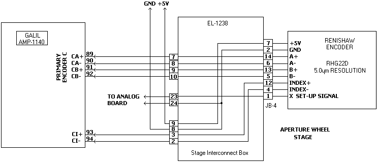
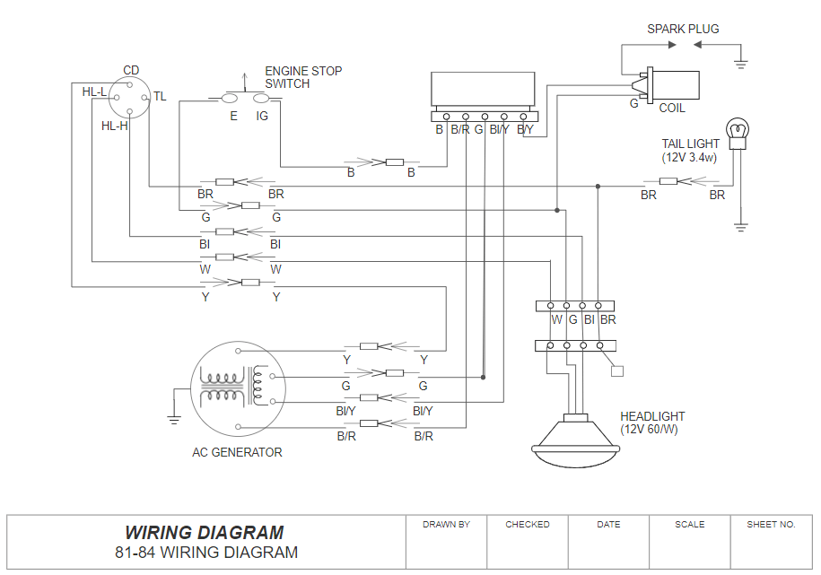
39 stage pin wiring diagram
PDF Standard AC with Standard Furnace Control Wiring Two Stage Heat Control Wiring 7 This diagram is to be used as reference for the low voltage control wiring of your heating and AC system. Always refer to your thermostat or equipment installation guides to verify proper wiring. NOTES Some AC Systems will have a blue wire with a pink stripe in place of the yellow or Y wire. 7.3l 42 Pin Connector Wiring Diagram 7.3l 42 Pin Connector Wiring Diagram. a connection again. Does anyone have the ohm readings/pinout schematic? Planning on testing from the 42 pin connector to the male valve cover connector/ Ford F L with k miles. 7 Stage Dp-Tuner. Start by testing from the valvecover connection to the injectors.
Dmx Cat5 Wiring - Wiring Diagrams Wiring Diagrams Doing an install and want to use the existing cat-5 wiring. I have patch bay access and many dry runs to near the pipe locations -some cat One of the most common cables found these days in buildings is the humble Cat5 cable.
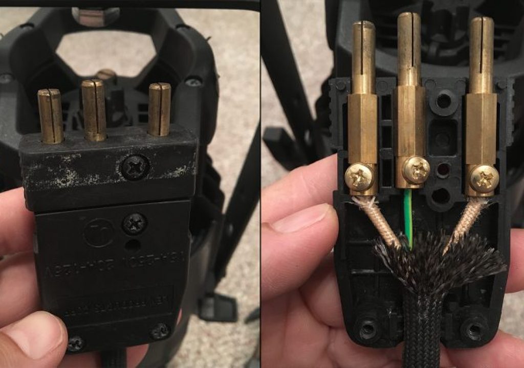
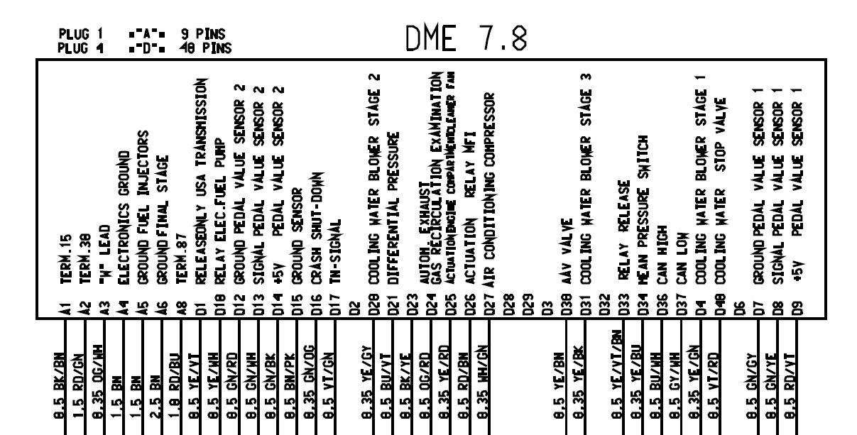
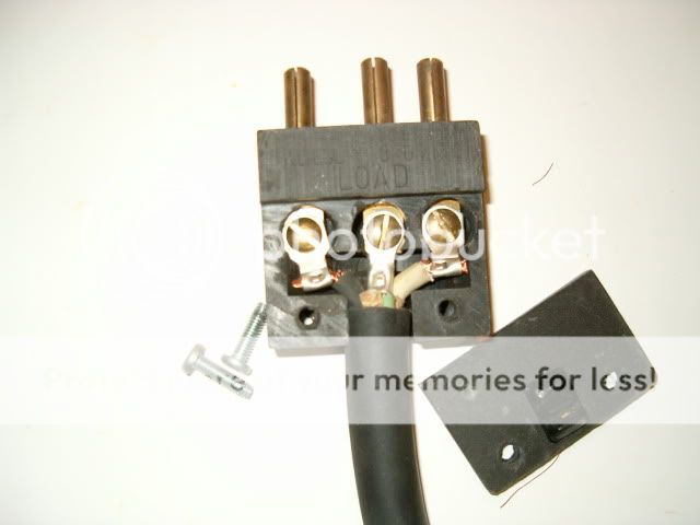
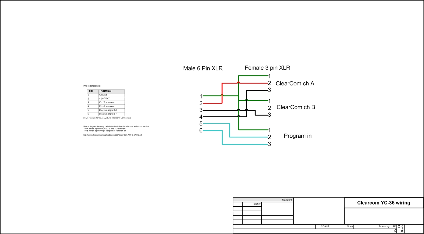
Stage pin wiring diagram
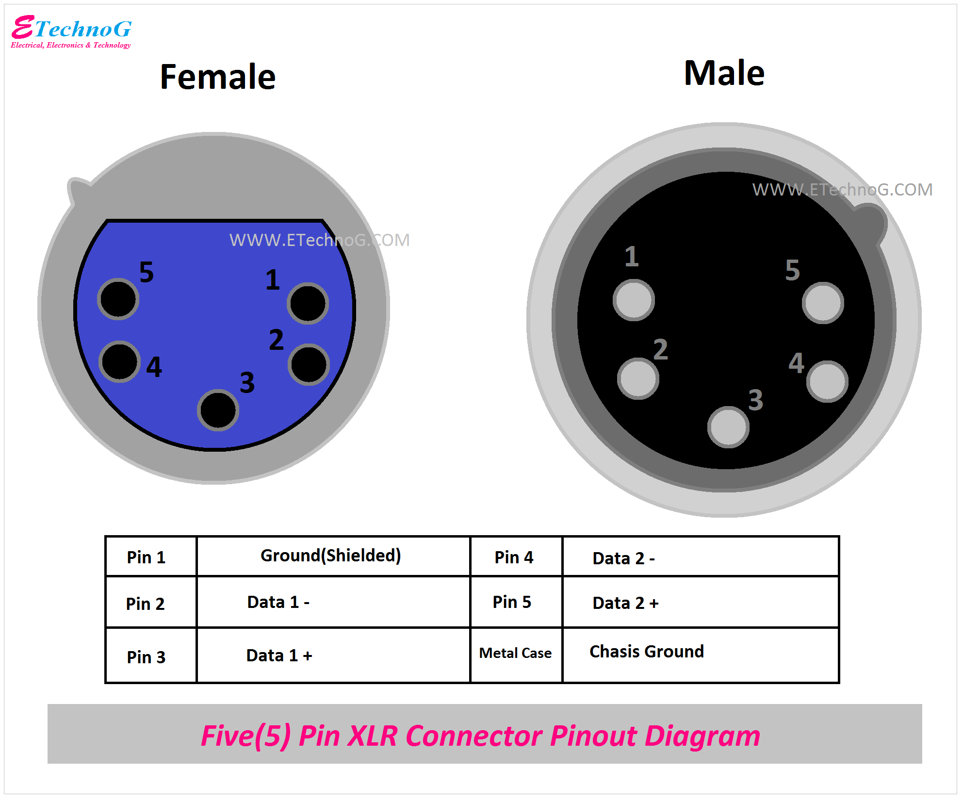
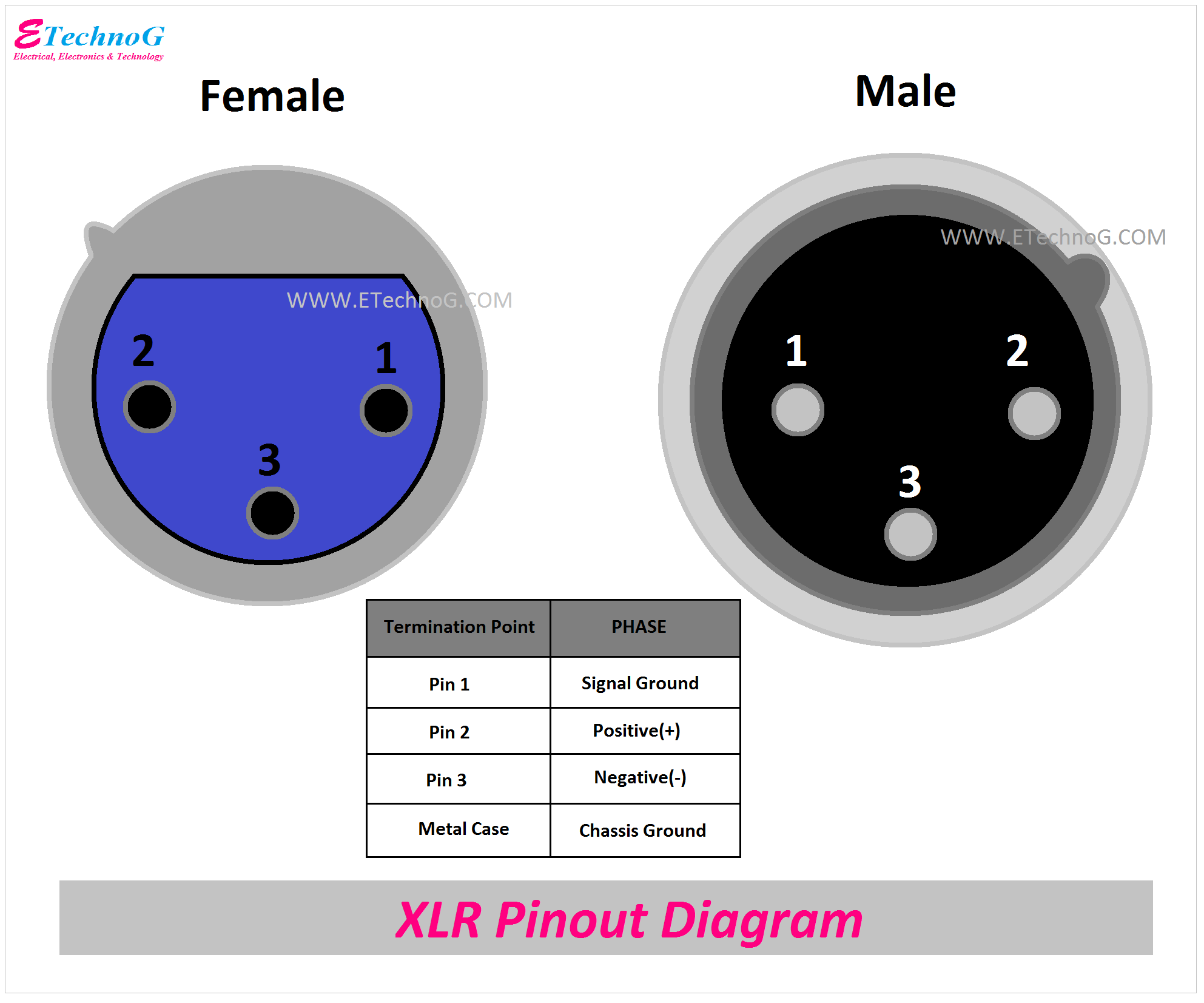
CD4060 14-stage Binary Ripple Counter - Microcontrollers Lab CD4060 IC is a 14-stage counter and counter is a binary ripple carry type. It is a CMOS logic-based binary counter belonging to a CD4000 series of integrated circuits. It consists of a 14-stage ripple carry binary counter along with an internal oscillator. Additionally, we can configure crystal oscillators with RC circuits or external crystal. 4 Pin Relay Wiring Diagram - U Wiring Relay 4 Pin 12v 30a Open Contact. Wiring Diagram for A 4 Pin Relay wiring diagram is a simplified agreeable pictorial representation of an electrical circuitIt shows the components of the circuit as simplified shapes and the capacity and signal connections with the devices. So a single pole double throw has a mutual. How to Wire DMX for Stage Lighting - Learn Stage Lighting .com Some splitters will feature a 3-pin or 5-pin for each output. When a splitter has both 3 and 5-pin on one labeled output, you will need to either choose between a 3-pin or 5-pin, you cannot use both! If the splitter's plugs are labeled separately on the output, then you are able to use each plug if needed.
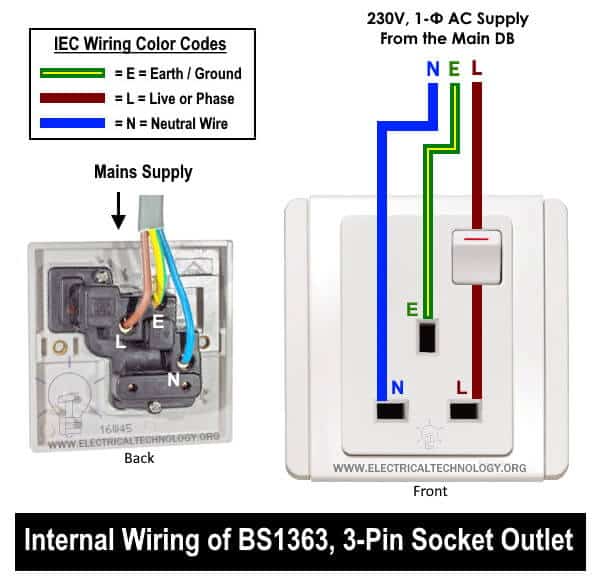
Stage pin wiring diagram. › projects › timed_fan_unitConnecting a Timed Fan Unit | How to Wire a Bathroom ... Diagram showing wiring method for an independently switched extractor fan Installing the Switched Fan The supply for this can be taken from most existing circuits providing the switched-fused-unit (SFU) is present at the start of the installation and appropriately fused to protect the sub-circuit cabling and accessories. Wiring Diagrams - Nitrous Outlet System Wiring Diagrams. Universal Single Stage Wiring Diagram. Universal Dual Stage Wiring Diagram. Dodge Ram 7 Pin Wiring Diagram - U Wiring Here is the diagram for 7-pin connector. I need a wiring diagram for a 7 pin trailer board plug. 02 dodge slt laramie white fass lift pump mbrp exhaust strait pipe with mbrp 6 inch black tip quadzilla adrenaline pulse v1 afe stage 1 intakediesel dynamics 60hp injectors 20. PDF Wiring Diagrams and Electrical Schematics wiring diagrams and electrical schematics f-250/350 pickup, in-bed tank wiring harnesses and connector layout in-bed lpa fuel tankfuel tank underhood harness ... 4 fuel pump #2 inline 2-pin 7 grommet underhood harness c3 underhood/can inline connector 2-pin c4 srm 46-pin underhood harness (cont.) c5 ipts 4-pin c6 frpcm 6-pin c7 flim 4-pin
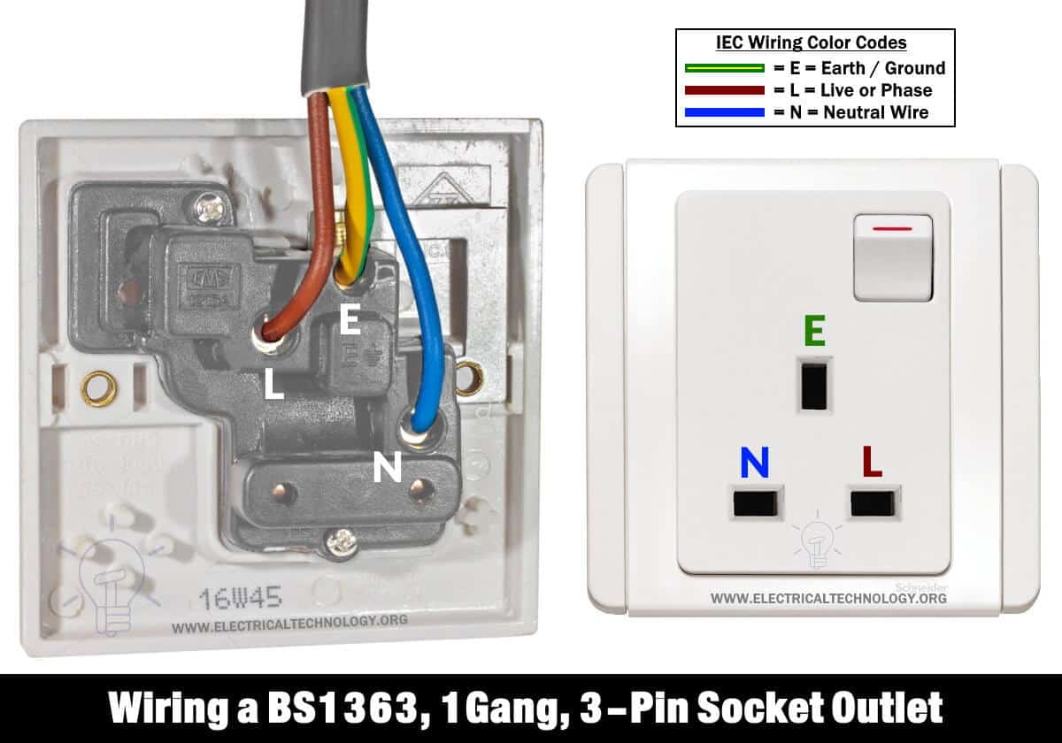
Socapex 19 Pin Circuit Drawings & Wiring Diagram - Phase 3 ... Socapex are a type of electrical connectors, known in the entertainment industry primarily for 19-pin electrical connectors. The Socapex was first created by a company called Socapex in 1961, but the term is now often applied to similar off-brand connectors as a genericized trademark, like Showsafe.The circular connectors are used in film, television, and stage lighting to terminate the ends ... 3 Phase 4 Pin Plug Wiring Diagram - Wiring Diagram 3 phase 4 pin plug wiring diagram. Help with 5 pin to 4 pin three phase. Stunning 3 pin plug wiring diagram contemporary electrical and img source. About 1 of these are power cords extension cords. First open the plug and locate the inscriptions. The 5 pin plug on the machine has two blacks one brown one blue and a greenyellow wires. Cat 6 Wiring Diagram - Wirings Diagram Cat 6 Wiring Diagram - cat 6 wiring diagram, cat 6 wiring diagram a or b, cat 6 wiring diagram australia, Every electrical arrangement is made up of various different components. Each part should be placed and connected with different parts in specific way. Otherwise, the arrangement won't function as it ought to be. Gas Furnace Wiring Diagram - Wirings Diagram Gas Furnace Wiring Diagram - carrier gas furnace wiring diagram, coleman gas furnace wiring diagram, gas furnace wiring diagram, Every electrical structure consists of various diverse parts. Each part should be placed and connected with other parts in particular way. Otherwise, the arrangement will not work as it ought to be.
Uniden 4 Pin Cb Mic Wiring Diagram - Wiring Diagram vs ... The following microphone wiring diagrams are for the majority of cb and 10 meter radios available. 4 pin (u) uniden microphone wiring (u) wiring to order a microphone with this wiring, just type your make and model into the microphone page, or simply 'u wired'. Kenwood ht's mic wiring color codes tx: 4 pin cb mic wiring diagram. › porschePORSCHE - Car PDF Manual, Wiring Diagram & Fault Codes DTC Hello, I’am looking for a steer wheel electrical circuit diagram for my 2004 Chevy suburban 5.3L 4wd Z-71 series 1500 CK-15906. Looking for the pin out diagram so that I can replace my wires back into the proper holes. Thank you for any help. #509. Edwin tejeda (Tuesday, 22 March 2022 19:41) Wiring in a 6 pin Connector...Need some help! | Dodge ... 1,430 Posts. #2 · May 20, 2008. I would say your best bet would be to get a test light and start in! the center for your 6 pin is for a constant HOT wire. You should be able to do away w/ the Purple as I think that is the Reverse lights. tape it back (after you check to make sure it is) I found this too! Wiring Diagrams - Honeywell Home Heating Controls Our Wiring Diagrams section details a selection of key wiring diagrams focused around typical Sundial S and Y Plans. Wiring Diagrams. Contains all the essential Wiring Diagrams across our range of heating controls. Click the icon or the document title to download the pdf. DOWNLOADS.
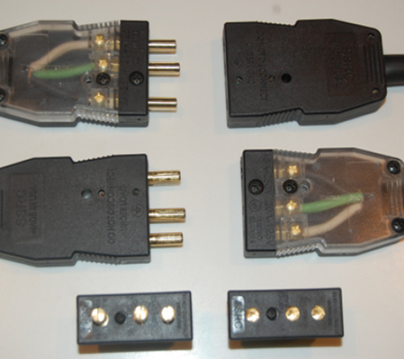
How to Wire DMX for Stage Lighting - Learn Stage Lighting .com Some splitters will feature a 3-pin or 5-pin for each output. When a splitter has both 3 and 5-pin on one labeled output, you will need to either choose between a 3-pin or 5-pin, you cannot use both! If the splitter's plugs are labeled separately on the output, then you are able to use each plug if needed.
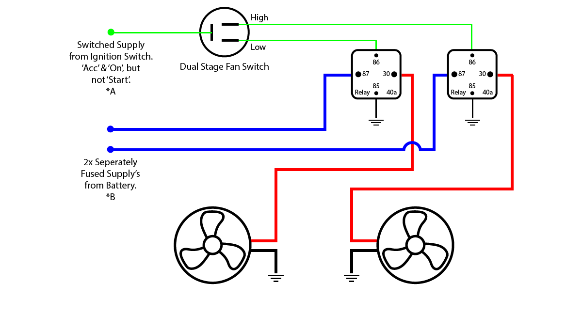
4 Pin Relay Wiring Diagram - U Wiring Relay 4 Pin 12v 30a Open Contact. Wiring Diagram for A 4 Pin Relay wiring diagram is a simplified agreeable pictorial representation of an electrical circuitIt shows the components of the circuit as simplified shapes and the capacity and signal connections with the devices. So a single pole double throw has a mutual.
CD4060 14-stage Binary Ripple Counter - Microcontrollers Lab CD4060 IC is a 14-stage counter and counter is a binary ripple carry type. It is a CMOS logic-based binary counter belonging to a CD4000 series of integrated circuits. It consists of a 14-stage ripple carry binary counter along with an internal oscillator. Additionally, we can configure crystal oscillators with RC circuits or external crystal.











![Energy Meter ET112 manual [Victron Energy]](https://www.victronenergy.com/live/_media/energy-meters:energy_meters_-_et112_-_2019-01-21.png)



0 Response to "39 stage pin wiring diagram"
Post a Comment