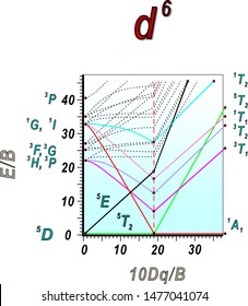
38 d6 tanabe sugano diagram
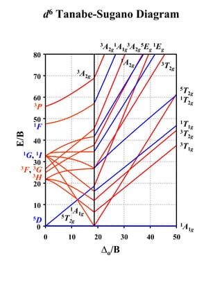
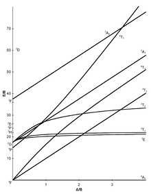
D8 Tanabe Sugano Diagram - Dubai Burj Khalifas Tanabe-sugano diagrams are used in coordination chemistry to predict absorptions in the uv, . d8 tanabe sugano diagram. d8 electron configuration . a step by step tutorial on assigning the transitions in the uv vis spectrum of a d7 system using a tanabe sugano diagram. d3 tanabe sugano diagram. 0. 0. 10 . d8 ν. 2. ν. 1. ratio. 0. 5. d6 low spin Tanabe-Sugano diagram d6 low spin Tanabe-Sugano diagram. Select the region of interest (usually between 20-40 Δ /B) then click on the curve to get values. See the instructions for more information. For the d 6 low spin case, the ground term is 1 A 1g which is plotted along the X-axis. The first spin-allowed transition is to the 1 T 1g level which is the red line. The second spin-allowed transition is to the 1 T 2g level (drawn in blue) and the remaining spin allowed transitions are very high in energy, so ignored.
Solved Shown below is the simplified Tanabe-Sugano | Chegg.com Chemistry questions and answers. Shown below is the simplified Tanabe-Sugano correlation diagram of d6 in the octahedral environment i. Explain briefly reasons for its construction and the relevance of the ii. Explain the apparent discontinuity at approximately 20 Ao/B, beyond which, ii. Predict the likely electronic absorption spectra of a d6 ...
D6 tanabe sugano diagram
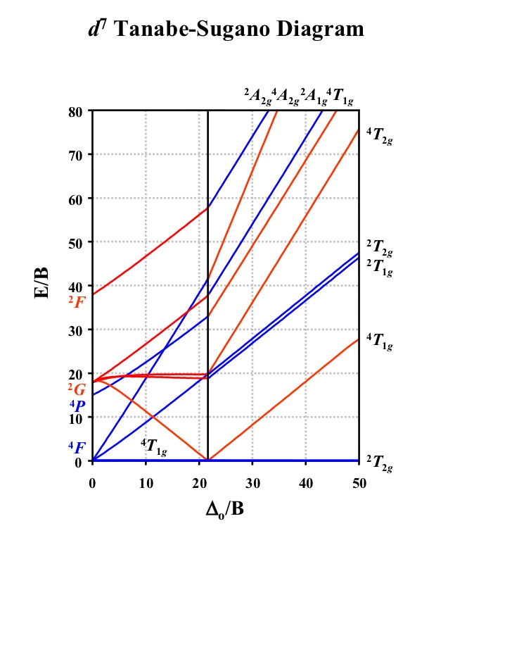
What is B in Tanabe-Sugano diagram ... How is the d7 Tanabe Sugano diagram used? Tanabe-Sugano diagrams are used in coordination chemistry to predict absorptions in the UV, . d7 Tanabe-Sugano diagram. d7 electron configuration. Select the region of interest then click on the curve to get values. See the instructions for more information. For the high spin d7 case, the. d7 Tanabe ... Tanabe–Sugano diagram - Wikipedia Tanabe–Sugano diagrams are used in coordination chemistry to predict absorptions in the UV, visible and IR electromagnetic spectrum of coordination compounds. The results from a Tanabe–Sugano diagram analysis of a metal complex can also be compared to experimental spectroscopic data. They are qualitatively useful and can be used to approximate the value of 10Dq, the ligand field splitting energy. Tanabe–Sugano diagrams can be used for both high spin and low spin complexes, unlike Orgel ... PDF d Tanabe-Sugano Diagram Title: Microsoft PowerPoint - handout6b Author: Alan Jircitano Created Date: 11/22/2004 11:06:49 PM
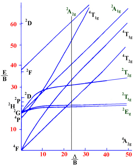
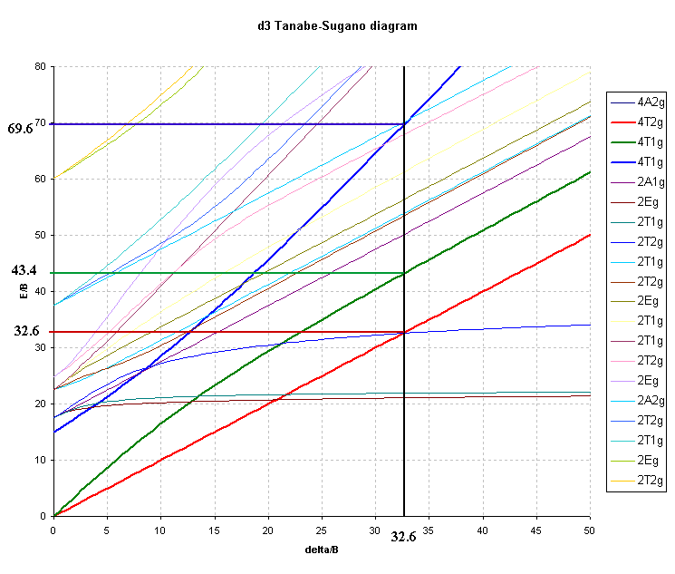
D6 tanabe sugano diagram. (PDF) d 2 Tanabe-Sugano Diagram | duda baif - Academia.edu d2 Tanabe-Sugano Diagram 1A 1E 1g g 80 3A 2g 70 60 1T 1g 1T 1S 2g 3T 50 1g E/B 40 3T 2g 1A 1g 30 1G 20 1E 3P g 1D 1T 2g 10 3F 3T 0 1g 0 10 20 30 40 ∆o/B d3 Tanabe-Sugano Diagram 4T 1g A2g 2 80 70 2A 1g 4T 60 1g 50 4T 2g E/B 40 2F 2T 2g 30 2T 1g 20 2E 2G g 4P 10 4F 4A 0 2g 0 10 20 30 40 50 ∆o/B d4 Tanabe-Sugano Diagram 3A Tanabe Sugano Diagram D6 - schematron.org Apr 06, 2019 · d6 low spin Tanabe-Sugano diagram. A Tanabe-Sugano diagram of some spin- allowed and forbidden transitions for low spin octahedral d6. Tanabe-Sugano diagrams are used in coordination chemistry to predict electromagnetic absorptions of metal coordination compounds of. Coordination Chemistry III: Tanabe-Sugano Diagrams and Charge Transfer. Interpretation of the Tanabe Sugano diagram | Physics Forums Looking at the Tanabe-Sugano diagram specifically for d 6 (Co 3+ is d 6) we can see that the transitions are 1 T 1g <-- 1 A 1g and 1 T 2g <-- 1 A 1g transitions (right hand side because there are 2 transitions and it is low spin). Then we find the ratio of the peaks 24,800/16,600 = 1.49, the next step is to find the D/B on the X axis: PDF d 2 Correlation Diagram - University of Massachusetts Boston Notes on d7 Tanabe-Sugano Diagram!The d 7 diagram, like all such diagrams for configurations that may be either high spin or low spin, has a perpendicular line near the middle marking the change in spin state. "To the left of the line (low field strength, high spin), the ground state is 4T 1, emerging from the free-ion 4F term.
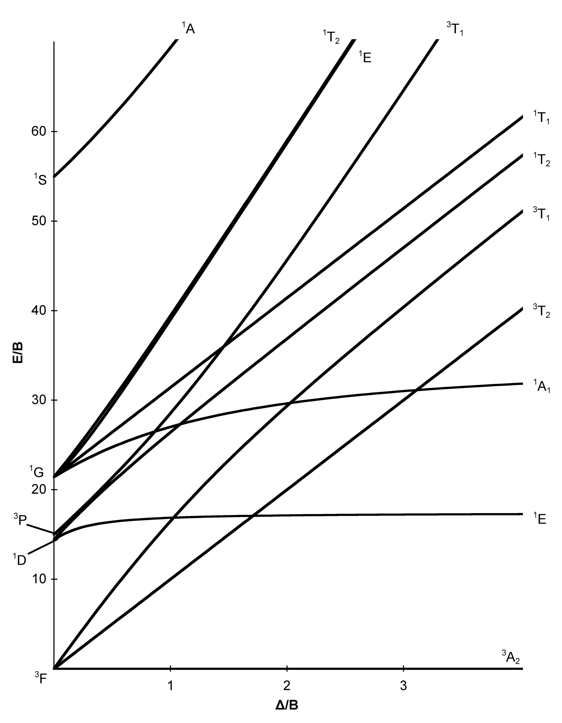
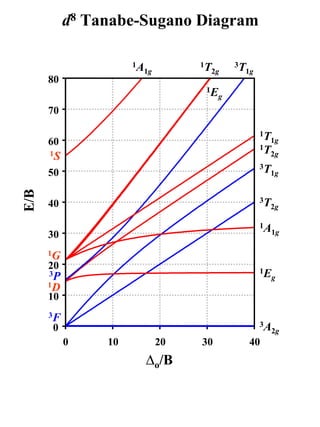
Analyzing an Octahedral Co(III) Complex Using a d6 Tanabe ... In this video we will determine the values for 10Dq and B for [Co(ox)3]3- using the d6 Tanabe-Sugano diagram.Video #1 on a 3d8 Oh species can be found here: ... Tanabe-Sugano Diagram - Parameters The x-axis of a Tanabe-Sugano diagram is expressed in terms of the ligand field splitting parameter, Dq, or Δ, divided by the Racah parameter B. The y-axis is in terms of energy, E, also scaled by B. Three Racah parameters exist, A, B, and C, which describe various aspects of interelectronic repulsion. A is an average total interelectron repulsion. PDF Coordination Chemistry III: Tanabe-Sugano Diagrams d2Tanabe-Sugano Diagram E / B ∆o/ B 3F 3P 3T 1g (3P) 3A 1g 3T 2g (3F) 3T 1g ~15B ~∆o ~∆o E1 E2 E3 E is the energy of the excited state relative to the ground state B is the Racah parameter for e--e-repulsion The example on page 427 of your text shows how to use this chart to fit the experimental data (E1, E2, and E3) for [V(OH2)6]3+to ... d6 high spin Tanabe-Sugano diagram d6 high spin Tanabe-Sugano diagram. spin-allowed transitions. SOLID LINES. 5 E g (D) ← 5 T 2g Red. spin-forbidden transitions. dotted lines. 1 T 1g (I) ← 5 T 2g Dk green. 1 A 1g (I) ← 5 T 2g Purple. 3 T 2g (F) ← 5 T 2g Blue.
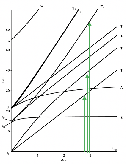
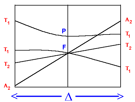
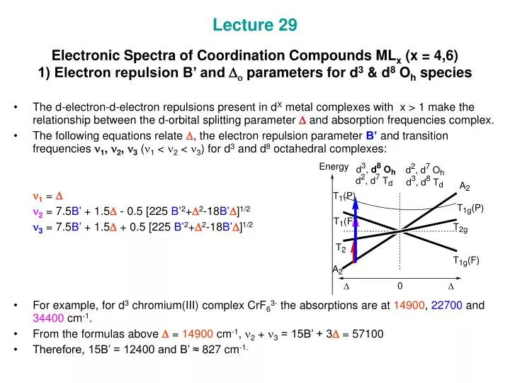
Tanabe-Sugano diagram with - Big Chemical Encyclopedia Tanabe-Sugano diagram with Tanabe-Sugano diagrams with representative values of C/B are given in Figures 12-15 for the lower lying terms of each of the cF configurations, n = 1-5. They can be used to deduce the principal features to be expected of the spectra of complexes of all the first transition metal ions in approximate octahedral or tetrahedral stereochemistry. Orgel and Tanabe-Sugano Diagrams for Transition Metal ... The section of "Orgel and Tanabe-Sugano Diagrams for Transition Metal Complexes (d1 - d9 States)" from the chapter entitled "Electronic Spectra of Transition Metal Complexes" covers the following topics: Orgel Diagrams: Orgel diagrams of d1, d9, d4, d6 systems; Orgel diagrams of d2, d8, d3, d7 systems; Orgel diagrams of d5 complexes. Solved (a) A Tanabe-Sugano energy level diagram for a d6 ... (a) A Tanabe-Sugano energy level diagram for a d6 octahedral complex is shown below. Note that the x-axis is actually Δ/B/10 (i.e., a value of 3 is actually 30 Δ/B) Numbered arrows representing d-d transitions are drawn at appropriate values of Δ /B for CoF63-and Co(H2NCH2CH2NH2)33+. What is B in Tanabe Sugano diagram? - Wherevermag In the case of Tanabe-Sugano diagrams each electron configuration split has an energy that can be related by the B value. A is ignored because it is roughly the same for any metal center and C generally approximated as being 1/4B. What B represents is an approximation of the bond strength between the ligand and metal.
Solved 2. Using the Tanabe-Sugano diagram for the d'ion ...
(PDF) Tanabe-Sugano Diagram | Sari Syahruni - Academia.edu d2 Tanabe-Sugano Diagram 1A 1E 1g g 80 3A 2g 70 60 1T 1g 1T 1S 2g 3T 50 1g E/B 40 3T 2g 1A 1g 30 1G 20 1E 3P g 1D 1T 2g 10 3F 3T 0 1g ∆o/B 0 10 20 30 40 d3 Tanabe-Sugano Diagram 4T 2 1g A2g 80 70 2A 1g 4T 60 1g 50 4T 2g E/B 40 2F 2T 2g 30 2T 1g 20 2E 2G g 4P 10 4F 4A 0 2g ∆o/B 0 10 20 30 40 50 d4 Tanabe-Sugano Diagram 3A 1 2g A2

Electronic Spectra of Transition Metal Complexes --- Part 5: Tanabe-Sugano Diagrams for d2 and d7
D6 Tanabe Sugano Diagram - schematron.org Jun 11, 2018 · on D6 Tanabe Sugano Diagram. in the Tanabe-Sugano diagrams for the d6 electron configuration of octahedral complexes. The error arises with the free ion term giving rise to the strong-field. Explanation about the different energy levels in the diagram. .. Fig Tanabe-Sugano diagram for d6 octahedral complex.
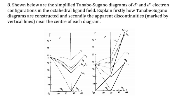
Solved 8. Shown below are the simplified Tanabe-Sugano ...
PDF Coordination Chemistry III: Tanabe-Sugano Diagrams and ... d7Tanabe-Sugano Diagram E / B ∆o/ B 4F 2G 2Eg 2T1g 2A1g 2T2g 4P 4A 2g 4T 1g ( 4P) 4T 2g 4T 1g ( 4F) Complexes with d4-d7 electron counts are special •at small values of ∆o/B the diagram looks similar to the d2diagram •at larger values of ∆o/B, there is a break in the diagram leading to a

Tanabe-Sugano-Diagramm – Wikipedia
T sdiagram - slideshare.net T sdiagram. 1. d2 Tanabe-Sugano Diagram 1A 1E 1g g 80 3A 2g 70 60 1T 1g 1T 1S 2g 3T 50 1g E/B 40 3T 2g 1A 1g 30 1G 20 1E 3P g 1D 1T 2g 10 3F 3T 0 1g 0 10 20 30 40 ∆o/B.
Calculation of Dq, B and β Parameters
Tanabe-Sugano Diagrams - Chemistry LibreTexts Tanabe-Sugano Diagrams. Tanabe-Sugano diagrams are used in coordination chemistry to predict electromagnetic absorptions of metal coordination compounds of tetrahedral and octahedral complexes. The analysis derived from the diagrams can also be compared to experimental spectroscopic data. Armed with spectroscopic data, an approximation to the ...
Tanabe-Sugano Diagrams - Chemistry LibreTexts
Tanabe Sugano Diagram D6 Mar 05, 2019 · Tanabe–Sugano diagrams are used in coordination chemistry to predict absorptions in the UV, . d6 Tanabe-Sugano diagram. d6 electron configuration.TANABE-SUGANO DIAGRAMS An alternative method is to use Tanabe Sugano diagrams, which are able to predict the transition energies for both spin-allowed and spin-forbidden transitions, as well as for both strong field (low spin), and weak field (high spin) complexes.
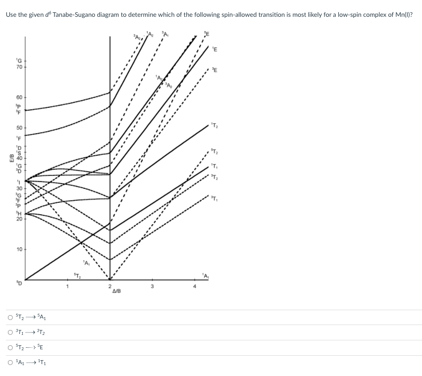
Solved Use the given d6 Tanabe-Sugano diagram to determine ...
Tanabe-Sugano diagram - Self-sufficiency Certain Tanabe-Sugano diagrams (d 4, d 5, d 6, and d 7) also have a vertical line drawn at a specific Dq/B value, which corresponds with a discontinuity in the slopes of the excited states' energy levels.This pucker in the lines occurs when the spin pairing energy, P, is equal to the ligand field splitting energy, Dq.
Calculations using Tanabe-Sugano diagrams
File:Tanabe Sugano Diagram d6.svg - Wikimedia Commons d6 Tanabe-Sugano Diagram. Captions. Summary . Description: English: The Tanabe-Sugano diagram for a d 6 transition metal ion. The energies are calculated using a Racah C = 4.5 B, and only selected states are depicted. The multiplicity of the ground state switches from a quintet to a singlet at the vertical line.
Tanabesugano Diagram Octahedral Complexes D6 Electronic Stock ...
Tanabe Sugano Diagram - d7 system - YouTube A step-by-step tutorial on assigning the transitions in the UV-vis spectrum of a d7 system using a Tanabe-Sugano Diagram.

Figure 3 from Photoactive Complexes with Earth-Abundant ...
PDF Orgel and Tanabe-Sugano Diagrams for Transition Metal ... d1, d9, d4, d6systems: For the "D" Orgel diagram, the left side contains d1and d6octahedral, and d4and d9tetrahedral complexes. The right side contains d4and d9octahedral, and d1and d6tetrahedral complexes. The lowest energy absorption band on the left side of the spectrum is T2g→ Egwhile on the right side of the spectrum it is Eg→ T2gtransition.
G - Tanabe-Sugano diagrams. ▫ A Tanabe-Sugano diagram is a ...
Diagrammes de Tanabe-Sugano - Wikipédia Les diagrammes de Tanabe–Sugano sont utilisés en chimie de coordination pour prédire l'absorption dans le spectre électromagnétique UV, visible et IR d'un ...

Tanabe–Sugano diagram - Wikiwand
PDF Tanabe-Sugano Diagram Jahn-Teller Effect Tanabe-Sugano diagrams can be used for both high spin and low spin complexes. Tanabe-Sugano diagrams can also be used to predict the size of the ligand field necessary to cause high-spin to low-spin transitions. In a Tanabe-Sugano diagram, the ground state is used as a constant reference. The energy of the ground state is taken to be

Part 2.9: Electronic Transitions - ppt download
PDF d Tanabe-Sugano Diagram Title: Microsoft PowerPoint - handout6b Author: Alan Jircitano Created Date: 11/22/2004 11:06:49 PM
Interpretation of the spectra of first-row transition metal ...
Tanabe–Sugano diagram - Wikipedia Tanabe–Sugano diagrams are used in coordination chemistry to predict absorptions in the UV, visible and IR electromagnetic spectrum of coordination compounds. The results from a Tanabe–Sugano diagram analysis of a metal complex can also be compared to experimental spectroscopic data. They are qualitatively useful and can be used to approximate the value of 10Dq, the ligand field splitting energy. Tanabe–Sugano diagrams can be used for both high spin and low spin complexes, unlike Orgel ...
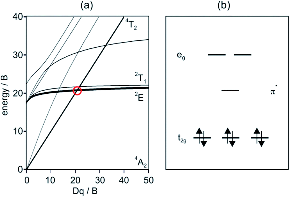
Chromium complexes for luminescence, solar cells, photoredox ...
What is B in Tanabe-Sugano diagram ... How is the d7 Tanabe Sugano diagram used? Tanabe-Sugano diagrams are used in coordination chemistry to predict absorptions in the UV, . d7 Tanabe-Sugano diagram. d7 electron configuration. Select the region of interest then click on the curve to get values. See the instructions for more information. For the high spin d7 case, the. d7 Tanabe ...
Electronic Spectroscopy.key
T sdiagram
d2 V3+. The complex will have a 3T1g ground state ...
Answered: Looking at a d6 Tanabe-Sugano diagram… | bartleby
Calculations using Tanabe-Sugano diagrams
8.2: Term splitting in ligand fields, selection rules, Tanabe ...
Calculations using Tanabe-Sugano diagrams

The d8 Tanabe Sugano Diagram and the Meaning of the Racha B Parameter
T sdiagram

File:Tanabe Sugano Diagram d5.svg - Wikimedia Commons
Datei:D6 Tanabe-Sugano diagram.png – Wikipedia
PPT - 2) Tanabe-Sugano diagrams. d 2 octahedral complexes ...

The Electronic Spectra of Coordination Compounds - ppt video ...

Datei:D6 Tanabe-Sugano diagram.png – Wikipedia

Tanabe-Sugano diagram for a 3d 2-ion in an ideal tetrahedral ...

Tanabe-Sugano-Diagramm – Wikipedia

Datei:D4 Tanabe-Sugano diagram.png – Wikipedia

Tanabe Sugano Diagram - d7 system

Tanabe Sugano Diagram with Examples, Spin Crossover, Questions from CSIR NET and GATE

Part 2 9 Electronic Transitions Outline Absorption spectroscopy
M.Sc Chemistry Inorganic Chemistry Semester-II
Tanabe-Sugano-Diagramm – Wikipedia

Ligandenfeldtheorie
0 Response to "38 d6 tanabe sugano diagram"
Post a Comment