38 Scully System Wiring Diagram
PDF Scully Groundhog LINE This system is ideal for top loading or applications where a Scully Overfill Prevention System is not in use. The control monitor connects to a heavy duty Sculcon® junction box with attached cable and special quick release snap-on plug. The Scully Ground Plug connects to a specially designed electronic Scully Ground Ball mounted on each vehicle. Scully Thermistor Wiring Diagram - Wiring Diagram Scully Thermistor Wiring Diagram. By Admin | November 6, 2017. 0 Comment. Scully thermistor socket acme fluid handling untitled 28 checkmate system with retain and overfill manualzz installation instructions real world solutions training pdf free sockets truck mounted prevention connectors ft208 5 wire support resources signal maintenance ...
Scully Grounding System Wiring Diagram - schematron.org Scully Grounding System Wiring Diagram. doubt that the grounding systems at your terminals are performing their The Scully Groundhog, when wired as a self-proving system, cannot be fooled by. Can be "straight' wired system (diagram next page) . 2-Wire Sensor Systems ( Like the Civacon ROM II or Scully IntelliCheck 2 Ground Bolt wired to Pin # 9.

Scully system wiring diagram
PDF INTELLICHECK ® Loading Rack Compatibility. Product ... the controller, wiring, connections and sensors are checked for faults up to 30 times per second. Only IntelliCheck ... IntelliCheck Overfill Only System Kit (100 feet scully cable) ... Size: Refer to diagram Weight: 6.5 lbs. (2.9 kg.) scully Scully Signal Company Scully System Wiring Diagram - Wiring Diagram Scully System Wiring Diagram. 28 checkmate system with retain and overfill manualzz untitled assistance ressources scully signal sockets truck mounted prevention connectors electronic component co wiring diagram circuit ground png 554x900px vdc001403 user manual 8 60982 st35 revk final for print ft208 5 wire installation instructions st 47 ... PDF Document in Microsoft Internet Explorer - SafeRack require additional wiring connections to both the API plug and automation system. Communication of Ground Verification and Overfill PERMIT is achieved through separate relay output contacts. Monitor status is displayed through the existing red and green status lights on the Scully enclosure.
Scully system wiring diagram. PDF Scully ST-47C Groundhog Scully ST-47C Groundhog Technical Manual ST-47C Series Self-Proving Vehicle Earthing Veri˜cation System Scully Signal Company / Tel. 617 692 8600 / Fax. 617 692 8620 / MaxSafety 800 2 SCULLY (272 8559) 70 Industrial Way, Wilmington, MA 01887-3479, USA / SYSTEMS sales@scully.com / Artec Minitron Wiring Diagram ackley machine, electrical enclosure mfg, lr systems, scully chart pens generic, hydromat inc, pengo, ty valve corp. I've got a Harvey Wells R9A receiver with no manual or schematic.., *0 if you .. we have found that Artec Inter- national has attractive prices — especially in line frequency operation) plus the 6 Minitron readouts will run you ... PDF Installation Instructions Remanufactured Veeder-Root ... Wiring the Overfill without an Acknowledgement Switch Wire used for this installation must have a rating of at least 90°C, must be 14 or 16 AWG and be color coded. Use the color illustration below as guide. However, the colors used are for clarity. The actual wire colors you use may be dictated by national and local codes. 1. PDF Installation Instructions API 5 wire FT101 sensors. FloTech recommends wiring the sensors to the FT208 Monitor using FT404 11 conductor cable for up to 8 compartment systems. FloTech FT404 cable is color coded to ease installation and troubleshooting. A color coded wiring schematic is provided in the back of this manual. TB5 Socket Connections
VDC001403 User Manual 8 Scully Signal VDC T—Ring wiring is provided via a short harness and must be extended using the coil harness and two conductor shield cable Scully part number 000766. T~Ring wiring should run along the vehicle side on which the fuel tank inlet is located. T-Ring harness should have a minimum clearance of 2" from all other wires and the harnesses. PDF Overfill System Training First determine the type of system (type of sensors used) • 5‐Wire Sensor Systems (Like the Civacon Liberty or Scully LA/GA) ‐Series wired 5‐wire sensors ‐Sensors operate and test just like a straight 5‐wire system • 2‐Wire Sensor Systems (Like the Civacon ROM II or Scully IntelliCheck 2 PDF Fault-finding, Tanker overfill protection 2 wire system. 4 Scully Optical 6.5 to 9.5 6.5 to 9.5 5 Scully Elec. Dummy 4.5 to 7.0 4.5 to 7.0 Compartment 3 has the higher voltage reading out of the three (3) Scully optical probes, so it is replaced and that fixes the problem. The probe is not necessarily faulty, the monitor channel many need an adjustment or there was a poor wiring connection in the tanker. Yong Heng Compressor Wiring Diagram - schematron.org Yong Heng Compressor Wiring Diagram 15.12.2018 15.12.2018 3 Comments on Yong Heng Compressor Wiring Diagram Yong Heng Compressor was a great alternative since I could get a water-cooled So i had to look up youtube videos and the instruction manual online.
PDF Single Point Overfill Prevention Controllers The system incorporates Scully's unique and exclusive Dynacheck concept. To ensure that the system will always detect an overfill condition, the controller uses pulsed signals which continuously check the entire system operation. The controller, wiring, connections and sensors are checked for faults up to 30 times per second. If a sensor PDF CIVACON OPTI-THERM RACK MONITOR SYSTEM and ASSOCIATED ... 3 SYSTEM CONTROL DIAGRAM FIGURE 2 - SYSTEM CONTROL DIAGRAM Notes: 1 - Control Equipment and Electrical Apparatus connected to the Rack Monitor should not use or generate more than 250 Volts. 2 - Installation should be in accordance with NEC ANSI/NFPA 70 and ANSI/ISA RP12.6 . In Canada, the SCULLY ST-47 SERIES TECHNICAL MANUAL Pdf Download | ManualsLib Summary of Contents for Scully ST-47 Series. Page 1 Scully ST-47 Groundhog Technical Manual ST-47 Series Self-Proving Vehicle Grounding Veri cation System Scully Signal Company / MaxSafety ® Tel. 617 692 8600 Fax. 617 692 8620 800 2 SCULLY (272 8559) SYSTEMS 70 Industrial Way, Wilmington, MA 01887-3479, USA... Home - Scully Signal Scully's inhouse manufacturing is vertically integrated with our own machine shop, diecast, electronic, and mechanical assembly. We have access to components and plenty of production capacity. Scully's core systems include—but are not limited to—overfull prevention, static ground proving, retained product monitoring, and oil delivery.
SCULLY - OVERFILL AND GROUND ·
PDF Installation Instructions Wiring Instructions It is highly recommended to use FloTech FT401 jacketed 7-conductor cable when wiring a new system. FloTech cable is designed to be oil, UV, and abrasion resistant. We incorporate a noble tin plated stranded copper wire which resist corrosion. These features will provide years of reliable service. 1.
2 wire SP-TO
Scully Wiring Diagram - Free PDF File Sharing scully load anywhere monitor ... 4402-4402 wiring diagram installed by civacon ground lug white (ground) orange red (power) field splice (ground) [Filename: Section5.pdf] - Read File Online - Report Abuse. Civacon Section A Petroleum Trailer Parts. Scully Intellicheck 2 Monitor 2-wire system 09107 - Overfill and retain 09109 - Overfill only ...

Support/Resources - Scully Signal
PDF Liquip Sales Pty Limited Engineering Department 13 Hume ... Refer to system wiring diagrams 10 Monitor to truck plug For TP104 2 wire system, use 10 core overall screened. For TP103 5 wire system, use 5 core overall screened. Both cases minimum conductor size of each core is 1.5mm2 or 18AWG

Re-wiring Your Cafe Racer I Motorcycle Electrics 101 I ...
Scully - Overfill and Ground Scully plugs and cables are the product of years of industry experience and offer durable, efficient operation.They are designed for use only with the intrinsically safe output circuits of Scully's ST-35, ST-15 and Intellitrol ®.Scully Plugs and Cables are used to connect the Scully loading rack control monitor to the vehicle mounted socket ...
Untitled
PDF Scully ST-35 Technical Manual - jmesales.com the vehicle via a Scully plug and cable assembly. The system incorporates Scully's unique and exclusive Dynacheck® concept. To ensure that it will always detect an over˜ll condition, the controller uses pulsed signals which continuously check the entire system operation including the controller, wiring connections and sensors. If a sensor comes
Scully Groundhog Scully Groundhog
Scully Thermistor Wiring Diagram - Wiring View And ... Scully Thermistor Wiring Diagram. ... Scully thermistor socket acme fluid untitled 28 checkmate system with retain and installation instructions overfill training sockets truck mounted ft208 support resources signal maintenance operating troubleshooting ground faults at the st 15c series technical manual single point prevention kalymnos fuel ...
Scully ST-47C Groundhog
Support/Resources - Scully Signal POLICIES Conflict Minerals Statement Scully Ordering Terms and Conditions Scully Website Terms and Conditions DOCUMENTATION Storage Tank Equipment ST-15 WX Datasheets: ST15WX_US ST15WX_International ST15WX_French ST15WX_German ST15WX_Russian ST15WX_Spanish ST15WX_Portuguese Manuals: ST15 WX_Manual Safety Manual: ST15WX_Safety Manual SP-O Single Sensor Mounting Holder…

Support/Resources - Scully Signal
PDF Scully Load Anywhere System The Scully Load Anywhere System incorporates Dynacheck automatic and continuous self-testing circuitry. Dynacheck sends a pulsing signal throughout the entire system. All components including the controller sensors, wiring and connections are checked. If everything is working properly, the signal

Support/Resources - Scully Signal
PDF Scully Load Anywhere Wiring grounding systems ali yaqoob, scully overfill sensor 5 wire overfill probe 7 length, scully system wire diagram wiring source, intellitrol 2 overfill prevention and ground verification unit, 1965 chevy impala ignition switch wiring diagram ebooks, intellitrol2 scully signal, scully load anywhere system eneric ltd, tanker parts store scully overfill

SCULLY- SENSORS Dynacheck® – Self-Checking Circuitry
Get to Know the Scully ST-47 Groundhog The Scully Groundhog enables you to have complete confidence that grounding to the vehicle's frame has been accomplished. The Groundhog is an intelligent system that continuously and automatically monitors the grounding connection during the entire loading operation. If an earth tie-in is broken, the product is designed to immediately shut ...

SCULLY - OVERFILL AND GROUND |
PDF Scully Load Anywhere Overfill Prevention Monitor Manual & Scully "Load‐Anywhere" Models) 6. 9 Series wiring of each sensor to next sensor • "Return" (dry) signal from last sensor satisfies rack monitor or OBM. • Only first wet sensor is detected / displayed by a 5‐wire ...
IntelliCheck®2
PDF Document in Microsoft Internet Explorer - SafeRack require additional wiring connections to both the API plug and automation system. Communication of Ground Verification and Overfill PERMIT is achieved through separate relay output contacts. Monitor status is displayed through the existing red and green status lights on the Scully enclosure.
FloTech FT208 CheckMate Programmable Retain / Overfill ...
Scully System Wiring Diagram - Wiring Diagram Scully System Wiring Diagram. 28 checkmate system with retain and overfill manualzz untitled assistance ressources scully signal sockets truck mounted prevention connectors electronic component co wiring diagram circuit ground png 554x900px vdc001403 user manual 8 60982 st35 revk final for print ft208 5 wire installation instructions st 47 ...
Installation Instructions
PDF INTELLICHECK ® Loading Rack Compatibility. Product ... the controller, wiring, connections and sensors are checked for faults up to 30 times per second. Only IntelliCheck ... IntelliCheck Overfill Only System Kit (100 feet scully cable) ... Size: Refer to diagram Weight: 6.5 lbs. (2.9 kg.) scully Scully Signal Company

SCULLY SP-IR INSTALLATION AND OPERATING INSTRUCTIONS Pdf ...

Wiring Diagrams & Installation Docs – Skully Customs

2 Wire System - Black and White Wires Revised - 0 | PDF ...
Installation Instructions
VDC001403 User Manual 8 Scully Signal

Scully IntelliCheck®3 Overfill Control Unit

Section 5 Overfill Protection

Support/Resources - Scully Signal

Support/Resources - Scully Signal

Support/Resources - Scully Signal

REAL WORLD. REAL SOLUTIONS. Overfill System Training - PDF ...
Installation Instructions
Scully Technical Manual ST-15C Series Single Point Overfill ...
Section 5 Overfill Protection
Untitled
Support/Resources - Scully Signal
Scully Technical Manual ST-15C Series Single Point Overfill ...

SCULLY - OVERFILL AND GROUND |
Scully ST-47C Groundhog
scully

Support/Resources - Scully Signal
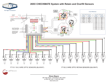
28XX CHECKMATE System with Retain and Overfill | Manualzz
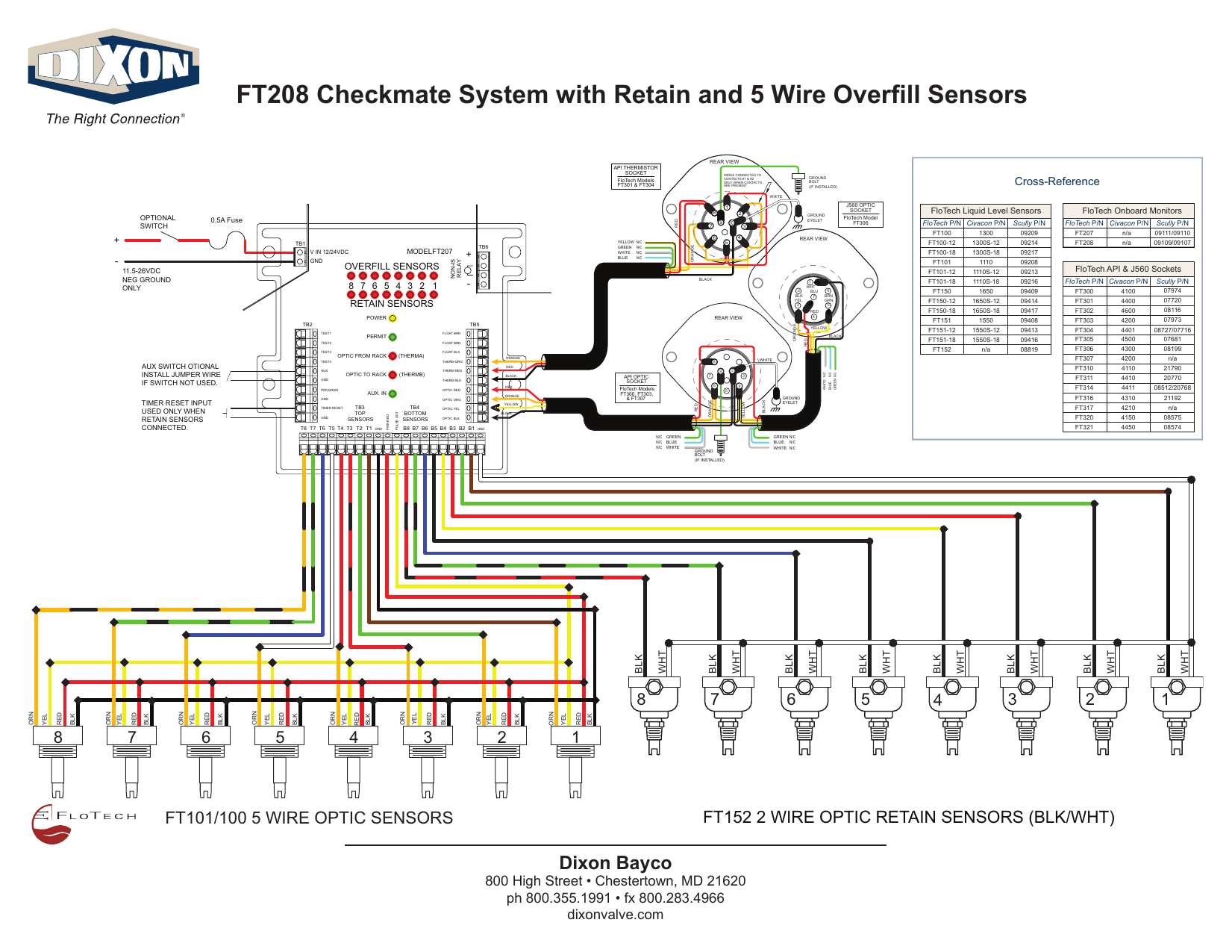
FT208 Checkmate System with Retain and 5 Wire | Manualzz
Scully Sockets: Truck Mounted Overfill Prevention System ...
0 Response to "38 Scully System Wiring Diagram"
Post a Comment