37 jk flip flop state diagram
Hi does anyone know a good single jk flip flop ic that is easy to solder to? 3-4 VDC? Thanks! Construst the state table as below: Execution table for jk flip flop: The state diagram for this counter is given in the following figure. The first one should count even numbers: Design a counter with the following binary sequence: 1, 2, 5, 7 and repeat. The state diagram for this counter is given in the following figure.
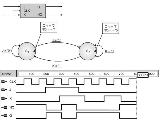
The Master Slave JK Flip-Flop Timing Diagram February 13, 2012 ECE 152A - Digital Design Principles 18 The JK Flip-Flop (cont) What happens if J = K = 1 for an indefinite period of time (i.e., much greater than clock period)? Output oscillates at ½ the frequency of the clock Divide by two counter
Jk flip flop state diagram
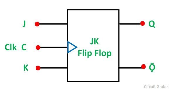
designed. Alternatively obtain the state diagram of the counter. • Determine the number and type of flip-flop to be used. • From the excitation table of the flip-flop, determine the next state logic. • From the output state, use Karnaugh map for simplification to derive the circuit output functions and the flip-flop output functions. In Fig 1 you can see the symbolic diagram of JK flip flop. We will know about its different case and from these cases we will also design its truth table. Fig 1. Graphical symbol of JK flip flop WORKING OF JK FLIP FLOP:- We will understand the working of JK flip flop with the help of NAND gate as you see in fig 2. 3. a flip-flop is a type of circuit that contains two states and are often used to store state information. by sending a signal to the flip-flop, the state can be changed. flip-flops are used in a number of electronics, including computers and communications equipment. there were a number of types of flip-flops are d flip-flop, sr flip-flopt …
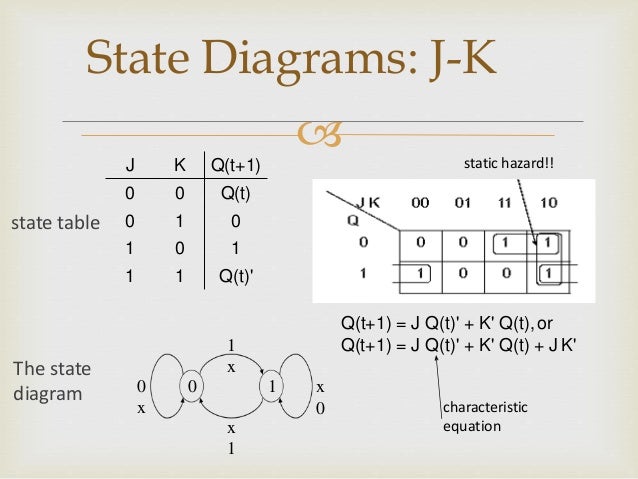
Jk flip flop state diagram. So i got a exercise where it ask what condition would be if CLK = 0,J =1 & K = 0. What condition happens? What do these pink, green, and blue mean? And why specify NOR? [https://imgur.com/a/pC07mz5](https://imgur.com/a/pC07mz5) State diagram for JK-flip-flop. digital-logic flipflop state-machines. I'm trying to create a simple state-diagram for a JK flip-flop, and this is what I've come up with. I've seen other variants of this diagram, but to me this seems like a correct one if you look at the state table: Circuit, State Diagram, State Table State: flip-flop output combination Present state: before clock Next state: after clock State transition <= clock 1 flip-flop => 2 states 2 flip-flops => 4 states 3 flip3 flip-flops => 8 statesflops => 8 states 4 flip-flops => 16 states
A theoretical schematic circuit diagram of a level triggered JK master slave flip-flop is shown in Fig 5.4.3. Gates G1 and G2 form a similar function to the input gates in the basic JK flip-flop shown in Fig. 5.4.1, with three inputs to allow for feedback connections from Q and Q.. Gates G3 and G4 form the master flip-flop and gates G7 and G8 form the slave flip-flop. Figure JKSM-1 is an example state machine using J-K flip-flops. Reading the logic diagram, we can derive the following excitation equations: Substituting into the characteristic equation for J-K flip-flops, we obtain the transition equations: J0 = X ⋅ Y′ K0 = X ⋅ Y′ + Y ⋅ Q1 J1 = X ⋅ YQ0 + K1 = Y ⋅ Q0′ + X ⋅ Y′ ⋅ Q0 Feb 24, 2012 · A JK flip-flop is a sequential bi-state single-bit memory device named after its inventor by Jack Kil. In general it has one clock input pin (CLK), two data input pins (J and K), and two output pins (Q and Q̅) as shown in Figure 1. JK flip-flop can either be triggered upon the leading-edge of the clock or on its trailing edge and hence can ... State diagram for JK-flip-flop. Ask Question Asked 6 years, 8 months ago. Active 6 years, 4 months ago. Viewed 2k times 0 \$\begingroup\$ I'm trying to create a simple state-diagram for a JK flip-flop, and this is what I've come up with. I've seen other variants of this diagram, but to me this seems like a correct one if you look at the state ...
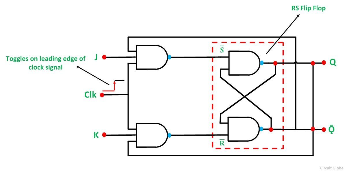
The circuit diagram of the J-K Flip-flop is shown in fig.2 . Fig.2 The old two-input AND gates of the S-R flip-flop have been replaced with 3-input AND gates .And the third input of each gate receives feedback from the Q and Q' outputs. The circuit diagram of the JK Flip Flop is shown in the figure below: The S and R inputs of the RS bistable have been replaced by the two inputs called the J and K input respectively. Here J = S and K = R. 3. the state table representation of a sequential circuit consists of three sections labeled present state, next state and output. the present state designates the state of flip-flops before the occurrence of a clock pulse. the next state shows the states of flip-flops after the clock pulse the output section lists the value of the output … This video explains the state diagram, state table and VHDL code for J-K flip flop.Dr. A. V. ThalangeAssociate Professor,E&TC Dept.,WIT, Solapur
What is JK Flip Flop? Circuit Diagram & Truth Table - Circuit ...
About Press Copyright Contact us Creators Advertise Developers Terms Privacy Policy & Safety How YouTube works Test new features Press Copyright Contact us Creators ...
Synchronous Sequential Logic Chapter 5 5 1 Introduction
A state machine diagram models the behaviour of a single object, specifying the sequence of events that an object goes through during its lifetime in response to events. As an example, the following state machine diagram shows the states that a door goes through during its lifetime. ... This is simply a JK flip-flop whose output alternates ...
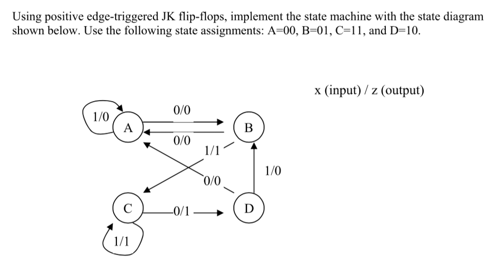
Solved Using positive edge-triggered JK flip-flops, | Chegg.com
The JK Flip Flop is a gated SR flip-flop having the addition of a clock input circuitry. The invalid or illegal output condition occurs when both of the inputs are set to 1 and are prevented by the addition of a clock input circuit. So, the JK flip-flop has four possible input combinations, i.e., 1, 0, "no change" and "toggle".
I'm struggling with writing the truth table for this state ...
JK Flip Flop-. JK flip flop is a refined & improved version of SR Flip Flop. that has been introduced to solve the problem of indeterminate state. that occurs in SR flip flop when both the inputs are 1. In JK flip flop, Input J behaves like input S of SR flip flop which was meant to set the flip flop. Input K behaves like input R of SR flip ...

المعكرونة شهواني منقي state diagram sr flip flop ...
Problem: Design a 11011 sequence detector using JK flip-flops. Allow overlap. Step 1 – Derive the State Diagram and State Table for the Problem. Step 1a – Determine the Number of States. We are designing a sequence detector for a 5-bit sequence, so we need 5 states.

Digital Circuits and Systems - Circuits i Sistemes Digitals ...
Sep 29, 2017 · The J (Jack) and K (Kilby) are the input states for the JK flip-flop. The Q and Q’ represents the output states of the flip-flop. According to the table, based on the inputs, the output changes its state. But, the important thing to consider is all these can occur only in the presence of the clock signal. This, works like SR flip-flop for the ...
state diagrams of flip flops
A JK flip-flop has two inputs similar to that of RS flip-flop. We can say JK flip-flop is a refinement of RS flip-flop. JK means Jack Kilby, a Texas instrument engineer who invented IC. The two inputs of JK Flip-flop is J (set) and K (reset). A JK flip-flop is nothing but a RS flip-flop along with two AND gates which are augmented to it.
Finite State Machines | Sequential Circuits | Electronics ...
Only 1 jk flip flop is given. I have to show that the led lights up only when j=1, k=1. How can i do it? *No other logic gate is allowed*
J-K Flip-Flop
The master flip flop toggles on the clock's positive transition when the inputs J and K set to 1. At that time, the slave flip flop toggles on the clock's negative transition. The flip flop will be disabled, and Q remains unchanged when both the inputs of the JK flip flop set to 0. Timing Diagram of a Master Flip Flop:

Solved) - Implement the state diagram of Exercise 3 using JK ...
Hey Everyone - got a big issue for me (likely small issue for someone who's got some exp). I'm making a menu overlay for a sub monitor (first time) and I'm having trouble with the logic required to turn on/off different cameras/gps/sonar, etc. My lua script has a 4 button menu, each goes to a different video feed. The purpose is when clicked/toggled between, the different video channels pop up. I'm getting hung up on turning off the channels if a button is clicked twice. Current: No channe...
1. dia
Problem: Design a 11011 sequence detector using JK flip-flops. Allow overlap. Step 1 - Derive the State Diagram and State Table for the Problem Step 1a - Determine the Number of States We are designing a sequence detector for a 5-bit sequence, so we need 5 states.
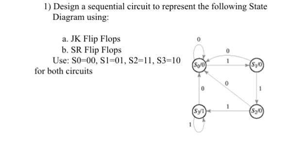
Solved) : 1 Design Sequential Circuit Represent Following ...
On this channel you can get education and knowledge for general issues and topics

State diagrams and flip flops
JK flip flop is a refined improved version of SR Flip Flop. Edge-triggered Flip-Flop State Table State Diagram. A state diagram is a diagram used in computer science to describe the behavior of a system considering all the possible states of an object when an event occurs. The circuit diagram of. Latches and Flip-flops PROCEDURE.
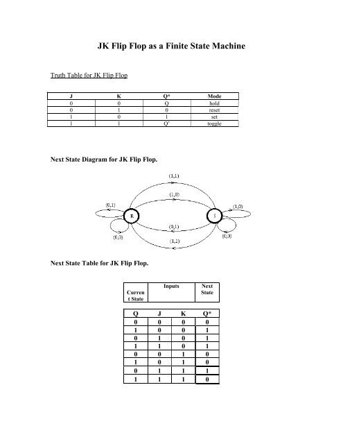
JK Flip Flop as a Finite State Machine
This video explains the state diagram state table and VHDL code for J-K flip flopDr. Step 1 Derive the State Diagram and State Table for the Problem Step 1a Determine the Number of States We are designing a sequence detector for a 5-bit sequence so we need 5 states. Data Storage using D-flip-flop Synchronizing Asynchronous inputs using D flip-flop.
JK-flipflop-State-Machine | Metastability Finite State ...
This symbol indicates that the JK flip-flop is a primary Nand gate RS flip-flop. It consists of a clock input circuit and the correct input signal. Additionally, the triangle sign beside the clock inputs indicates that these are edge-triggered devices. Hence flip-flops rather than latches. (example of complex devices that use the J-K flip flop.)
Realization Of ASM Charts
Hello, I am trying to create a super basic "t" latch for a project. From my understanding, I should use a JK flip flop and tie J and K together to create a t flip flop. But that leaves clock, and I don't really know what I should do. I want the project to always be able to toggle at any time no matter what, so should I just tie clock high or will that break it/not work? Thanks in advance for any input. It helps a lot.
JK Flip Flop
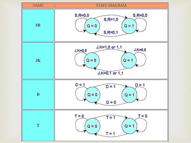
What is state diagram in flip flop? In addition to graphical symbols, tables or equations, flip-flops can also be represented graphically by a state diagram. In this diagram, a state is represented by a circle, and the transition between states is indicated by directed lines (or arcs) connecting the circles.
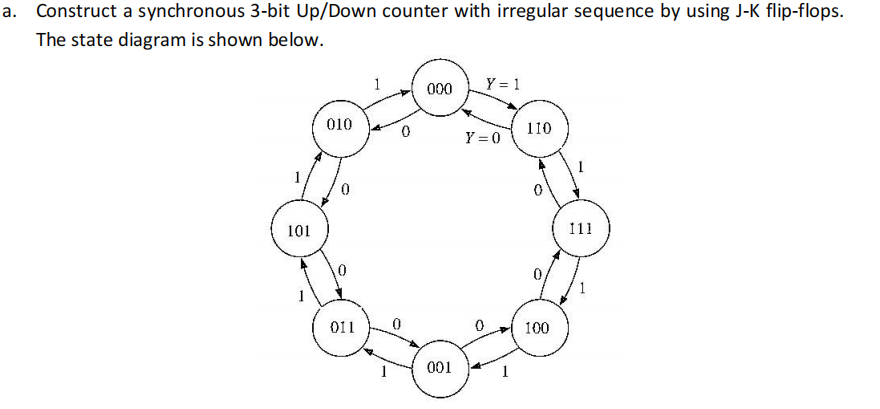
Answered: Construct a synchronous 3-bit Up/Down… | bartleby
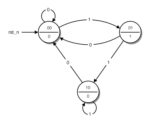
I dont understand what the outlying circles are for. Does that mean that the present state is undefined? [https://i.stack.imgur.com/SC7zt.png](https://i.stack.imgur.com/SC7zt.png)

JK Flip Flop and the Master-Slave JK Flip Flop Tutorial
Use K-map to derive the flip flop input functions. Design Problem #1 Design 3-bit synchronous up counter using JK flip flops. Step 1: Find the number of flip flops. A flip flop stores only one bit, hence for a 3 bit counter, 3 flip flops (n=3) are needed to design the counter.
What is JK Flip Flop? Circuit Diagram & Truth Table - Circuit ...
3. a flip-flop is a type of circuit that contains two states and are often used to store state information. by sending a signal to the flip-flop, the state can be changed. flip-flops are used in a number of electronics, including computers and communications equipment. there were a number of types of flip-flops are d flip-flop, sr flip-flopt …
Solved] Question 2 : Design the sequential circuit specified ...
In Fig 1 you can see the symbolic diagram of JK flip flop. We will know about its different case and from these cases we will also design its truth table. Fig 1. Graphical symbol of JK flip flop WORKING OF JK FLIP FLOP:- We will understand the working of JK flip flop with the help of NAND gate as you see in fig 2.
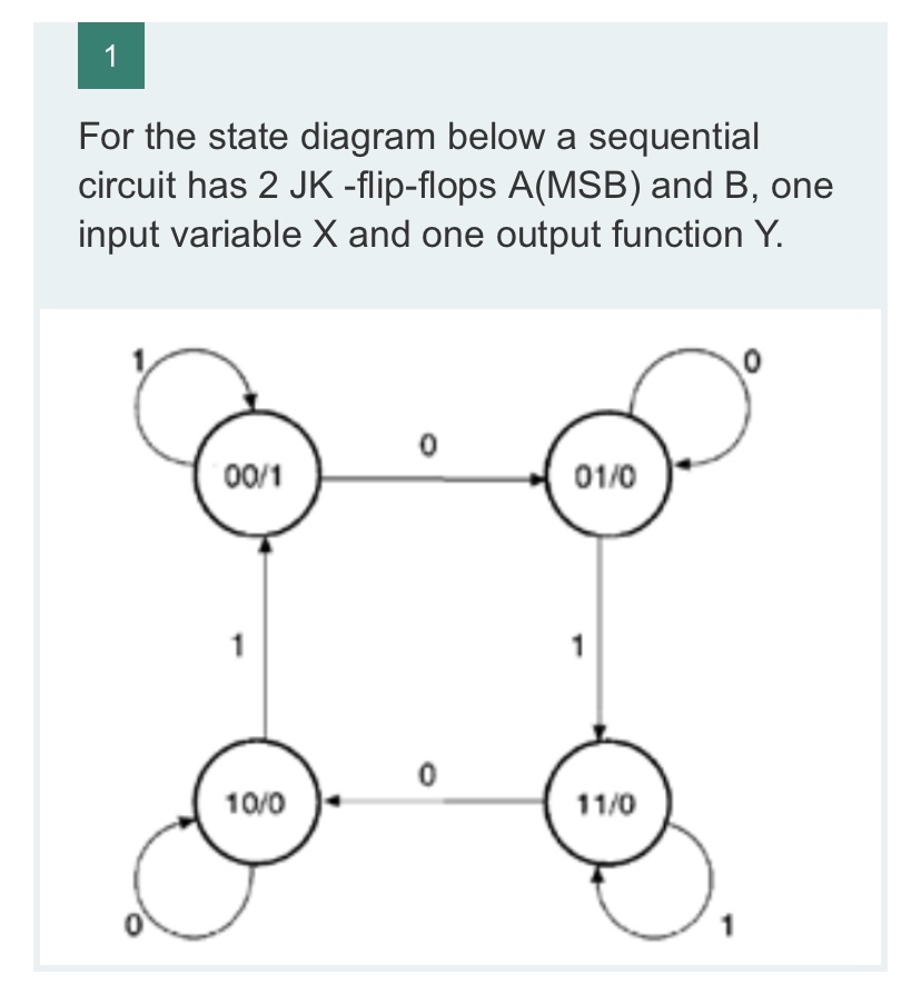
Answered: For the state diagram below a… | bartleby
designed. Alternatively obtain the state diagram of the counter. • Determine the number and type of flip-flop to be used. • From the excitation table of the flip-flop, determine the next state logic. • From the output state, use Karnaugh map for simplification to derive the circuit output functions and the flip-flop output functions.
Synchronous Sequential Logic Chapter 5 Other Flip Flops

State Diagram Of Sequential Circuit Using Jk Flip Flop(हिनà¥à¤¦à¥€ )

State diagrams and flip flops
Solved] A sequential circuit has two JK Flip-Flops. Given the ...
ECE-223, Solutions for Assignment #6
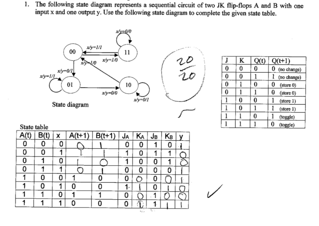
Solved 1. The following state diagram represents a | Chegg.com

Design of Sequential Circuits Using JK Flip Flops
Design The Sequential Circuit With Respect To The Following ...
Solved) : Sequential Circuit 1 Input X Amd 1 Output Y State ...
state diagrams of flip flops
â‘ Part I: Analysis â‘ Part 2: Synthesis (Design) â‘ Part 2 ...

A sequential circuit with 2 JK flip-flops, A and B; 2 inputs ...

2. Design a 4-bit binary up counter (like the followin ...
â– Exo_01: A sequential circuit has two Jk flip-flops, A and ...
Finite State Machine
0 Response to "37 jk flip flop state diagram"
Post a Comment