36 Definite Purpose Contactor Wiring Diagram
Definite Purpose Contactors and Starters Product Overview—Contactors and Starters Catalog Number Selection Definite Purpose Control—Contactors and Starters Notes 1 Not available on 50A devices. 2 Vertical in-line quick connect terminals on 60A and 75A F frame. Model C = Contactor A = Three-phase starter B = Single-phase starter Type 25 = Non-reversing contactors and starters (C306) PDF Definite purpose contactors and starters Definite Purpose Control—Contactors and Starters. comprehensive line of definite purpose contactors in. Wiring Diagrams. Three-Phase Connections. Wire "C" (Supplied with Common Control).
Definite Purpose Contactors Carlo Gavazi | PDF | Inductor Definite Purpose Contactors. 1, 2 and 3 pole Type GDP l DefinitePurpose Contactors l Switching Connection Diagrams 1 Pole with 1 auxiliary contact 1 Pole with shunt GDP251…01, GDP321..01 Coil terminals Contactor Series Screw Type Max wire size Max torque value Terminal Type and Size...
Definite purpose contactor wiring diagram
02 Contactors 12 Definite-purpose (DP) contactors are available. Consult Technical support for information; see contact. details on inside front cover. Dimensions pages 2-31 to 43. Wiring diagrams page 2-44. Technical characteristics page 2-48 to 69. 2 Contactors. PDF Definite Purpose Contactors l Definite Purpose Contactors l Switching up to 100A resistive, 90A inductive l Line Voltage up to 600VAC on most sizes l Control voltage up to 480VAC l Screw or box lug terminals available on most sizes l Fast-on coil and power terminal l Hp ratings on 3-pole contactors l UL recognized and CSA... PDF Definite Purpose Control Definite Purpose Contactors Types DP, DPA and SYD — Class 8910. Denite purpose contactors are ideal for heating, air conditioning, refrigeration, data They feature quick connect terminals and binder head screws for easy wiring. Box lugs are standard on 40 ampere contactors and larger.
Definite purpose contactor wiring diagram. PDF DET-833B Revised Definite Purpose Contactors Fact Sheet GE Industrial Solutions. Definite Purpose Contactors. 25-40 FLA Standard. GE's full complement of definite purpose contactors (20A-150A) are utilized in a variety of industrial electric equipment. #12-18AWG 10lb-in/1.1 N-m. Cu 75° C wire only. PDF Wiring Diagram Book WIRING DIAGRAM A wiring diagram shows, as closely as possible, the actual location of all component parts General Purpose Relays and Sensing Relays Class 8501 and Telemecanique RM2 LA1/LG1. Wiring Diagram. Class 8502 Type PF, PG or PJ Contactor w/ Class 9065 Type TF, TG... Eaton Definite Purpose Contactor Wiring Diagram - 29 Dc Contactor Wiring Wiring Diagram 500. Definite Purpose Dp Contactors Eaton. Xtce009b10td. Contactor For Double Pole Wiring Diagram. C25bnb230a. PDF Definite Purpose Contactors Definite purpose contactors. 20 A to 60 A. Full Load Amps. 9 6 2100. 1 See diagram on page 7 for approximate dimensions and description 2 Stranding must be split for # 8 wire. Discount Schedule DS-DP. 4.
Definite Purpose Contactor Wiring Diagram - Free Catalogs A to Z Definite Purpose (DP) Contactors. 4 hours ago wiring the contactor into the system. Just Now Single pole lighting contactor wiring how to wire a 8 steps with issue definite purpose shower question an mcb and rccd asco 918 contactors drawing diagram 917 remote contactorotor starters... Definite Purpose Contactor Wiring Diagram - Free Wiring Diagram A wiring diagram usually gives info concerning the relative position as well as arrangement of devices and terminals on the tools, in order to help in structure or Size: 218.38 KB. Dimension: 990 x 815. Variety of definite purpose contactor wiring diagram. Click on the image to enlarge, and then save... PDF Definite purpose contactors — Definite purpose contactors The complete range. Applications Type DP contactors provide high performance with flexibility and reliability, designed to match numerous applications including: • Motors • Power supplies • Food service equipment • Compressors • Business machines • Resistive heating... Contactor : Construction, Working Principle, Types and Differences What is Contactor? Definition: Contactors are electrically controlled switching devices which are used for switching block-diagram-of-contactor. Working Principle of Contactors. An electromagnetic field is generated The three colored phase wires are connected to three terminals T1, T2, T3 of machine.
Eaton Definite Purpose Contactor Wiring Diagram Definite Purpose Dp Contactors Eaton. Eaton C25cnb130t Definite Purpose Contactor Type C25 1 Pole. Xtce009b10td. Contactor For Double Pole Wiring Diagram. C25bnb230a. DEFINITE PURPOSE CONTACTOR WIRING DIAGRAM - Auto... Related searches for definite purpose contactor wiring diagram square d lighting contactor diagramac contactor wiring diagramcontactor schematic diagramwiring a contactor diagrammagnetic contactor wiring diagram2 pole contactor wiring diagramcontactor circuit diagramdefinite purpose... Definite Purpose Contactor Wiring Diagram - Wiring Diagram Source Starter Wiring Diagram Additionally 3 Phase Air Pressor Wiring. C common control wiring s separate control wiring enclosure type n open with metal mounting plate. Definite purpose contactor wiring diagram. Definite purpose controlcontactors and starters notes 1 not available on 50a devices. Iec Contactor Wiring Diagram Dec 19, 2021 · Variety of definite purpose contactor wiring diagram. Lighting contactor wiring diagram with photocell elegant cool v wiring diagram contemporary electrical and wiring uploaded by alena on thursday september 14th in category wire diagram. Thus c1 contactor is also energized and three phase supply will reach to the motor. Green and red or start ...
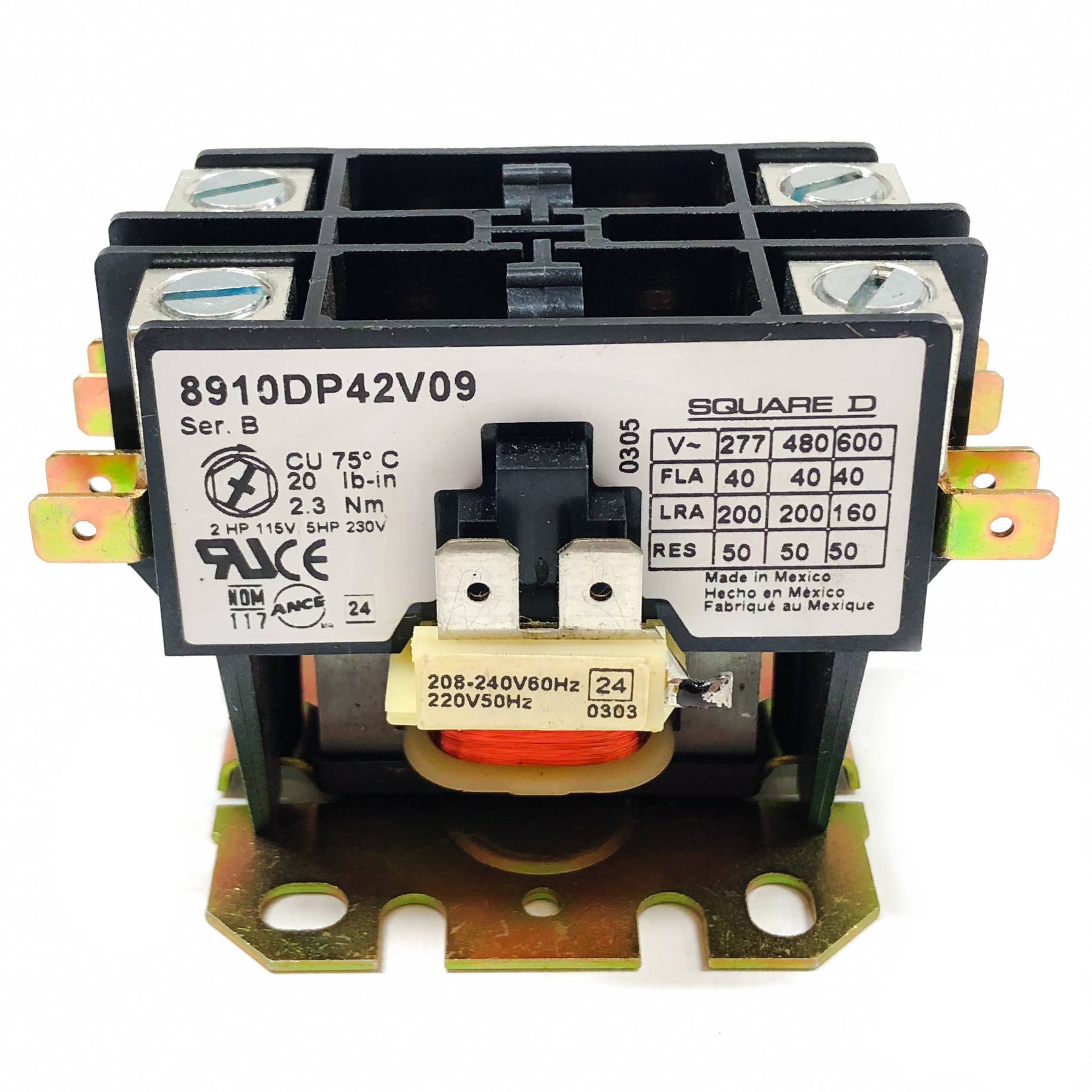
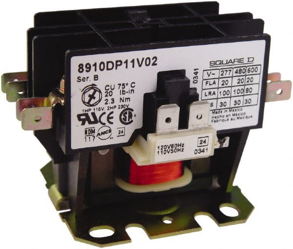
8910DP42V09 Square D Definite Purpose Contactor
Definite Purpose (DP) Contactors - Lowe's contactor. See Fig. 1. C See equipment manufacturer wiring instructions or Fig. 2. D Attach the line wires to the contactor using terminal clamp screws. E Attach the load wires using No. 10 binding screws. F Use pressure lugs for field wiring with wire larger than No. 8. SHEAR FORMED TAB SCREW CONTACTOR BASE M5513 Fig. 1. Typical contactor mounting. Model

New Imo Contactor Wiring Diagram #diagram #diagramtemplate ...
PDF Example wiring: PV shedding using definite purpose contactor with... Example wiring: Load shedding using definite purpose contactor with 120 Vac coil. Note: The definite purpose external contactor may make a humming or buzzing sound when its coil is Figure 2 Enpower Auxiliary contact wiring diagram. The line diagram represents both the Normally Opens...
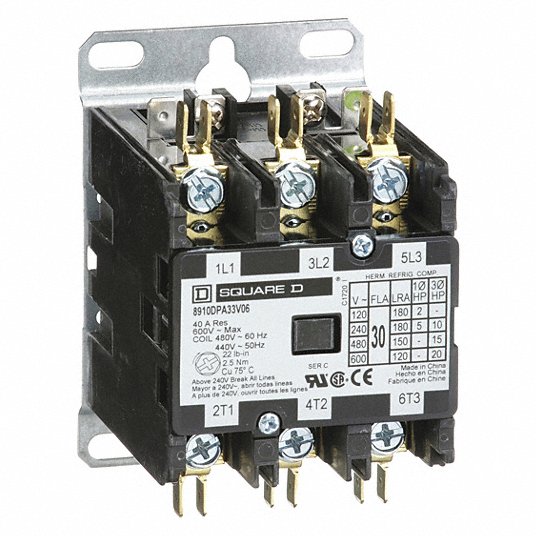
480V AC Definite Purpose Magnetic Contactor; No. of Poles 3, 30 A Full Load Amps-Inductive
35 Definite Purpose Contactor Wiring Diagram - Wiring Diagram... Definite purpose contactors and starters 41 product overviewcontactors and starters catalog number selection definite purpose controlcontactors and starters notes 1 not available on 50a devices. Definite purpose contactor wiring diagram.

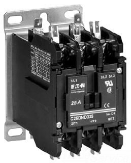
EATON CUTLER HAMMER C25DND330B Contactor, 30 A, Panel Mount, 230 V, 3PST, 3 Pole, 10 hp
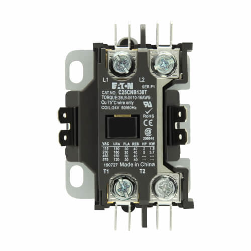
C25 Series D1 DEFINITE PURPOSE CONTACTOR DIAGRAM. AUXILIARY CONTACT INSTALLATION FIG. 2 AND FIG. 3 ... Remove Side Shield from side of Contactor where Auxiliary Contact will be ... #14-12 WIRE.
General + Definite Purpose Contactors
Definite Purpose Contactor Wiring Diagram Collection Print the electrical wiring diagram off and use highlighters in order to trace the circuit. When you make use of your finger or perhaps follow the circuit with your eyes, it may be easy to mistrace the circuit. 1 trick that We 2 to print the same wiring plan off twice.
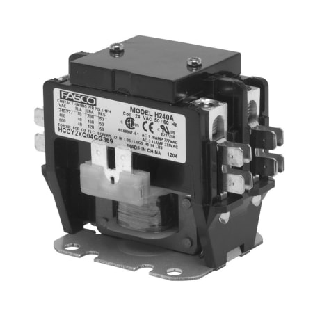
EIS | Fasco H240B Definite Purpose Contactor, 2-Pole, 40A, 120VAC
Definite Purpose (DP)P Contactors These electromagnetically-operated Definite Purpose. Contactors provide ... Attach the line wires to the contactor using terminal ... 2. Typical wiring diagram.
1-Pole Definite Purpose Contactor (277V, 30 Amp)
Definite Purpose Contactor Wiring Diagram | autocardesign A wiring diagram is often used to troubleshoot problems and to make determined that every the connections have been made and that all is present. definite purpose contactor wiring diagram free wiring. Architectural wiring diagrams put-on the approximate locations and interconnections of...

C25BNB220A Eaton Definite Purpose 2 pole Contactor rated at ...
Definite Purpose Contactors and Starters ...Purpose Contactors and Starters Product Overview—Contactors and Starters 4.1 Catalog Number Selection 4 Definite Purpose Control—Contactors and (CM) 4 Electrical/EMC 4 4 4 4 4 4 4 4 4 4 4 4 4 4 Wiring Diagrams Single-Phase Connections Three-Phase Connections Wire "C" (Supplied with...

How to wire motor control contactor
All About Definite Purpose Contactors | Wolf Automation What are definite purpose contactors? DP contactors are electronically controlled switches that are used for switching a power circuit. Originally designed for the HVACR industry, their use has expanded to a variety of other market segments. In general, if you have an application that heats, cools...
120VAC Non-Reversing Definite Purpose Contactor 3P 40A, Width: 2.5 in
Contactors | Electromechanical Relays | Electronics Textbook Read about Contactors (Electromechanical Relays) in our free Electronics Textbook. Wire connections to the "overload" switch contact may be seen at the lower-right of the photograph, near a motor through that phase of the contactor, you will read a definite millivoltage across that heater

I have a 8903 square d 10 pole lighting contactor need to - Fixya
Square D Definite Purpose Contactor Wiring Diagram ... Jul 12, 2019 · Square D Definite Purpose Contactor Wiring Diagram – wiring diagram is a simplified pleasing pictorial representation of an electrical circuit. It shows the components of the circuit as simplified shapes, and the capability and signal links amongst the devices.

How to wire contactor block
Contactor Coil Wiring Diagram - The Wiring Jan 19, 2022 · Variety of definite purpose contactor wiring diagram. LC1D25G7 – TeSys D IEC contactor, 25 A, 3 P, 15 HP at 480 VAC, nonreversing, 120 VAC 50/60 Hz coil. 3 Pole Contactor Wiring Diagram 3 Pole Contactor Wiring Diagram. The wiring diagram for a DOL stater is shown below.

Diversitech EC30224 2 Pole Definite Purpose Contactor, 30 Amp, 24 Vac Coil, Factory Minimum Order Qty: 30
What is Contactor? | All About Contactors | Wiring Diagram - YouTube In this video introduction of magnetic contactor, working principal of contactor, different parts and finally power and control wiring diagram of contactor...
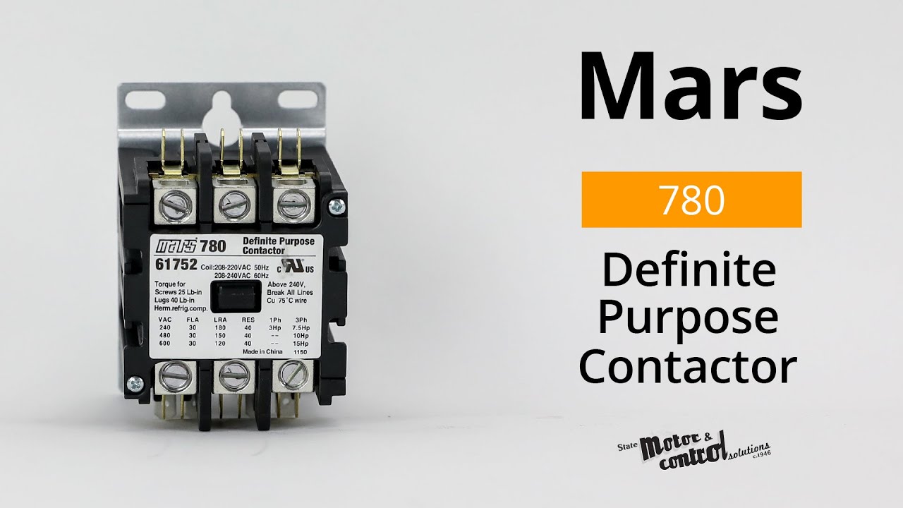
Mars 780, Definite Purpose Contactor
PDF Definite Purpose Contactors | Wiring Diagrams ITC's Definite Purpose (DP) Contactors are AC switching devices, particularly designed to operate components in the heating, ventilation, air conditioning, resistance heating industry. Wiring Diagrams. Definite Purpose Contactors (Order by Part No.)
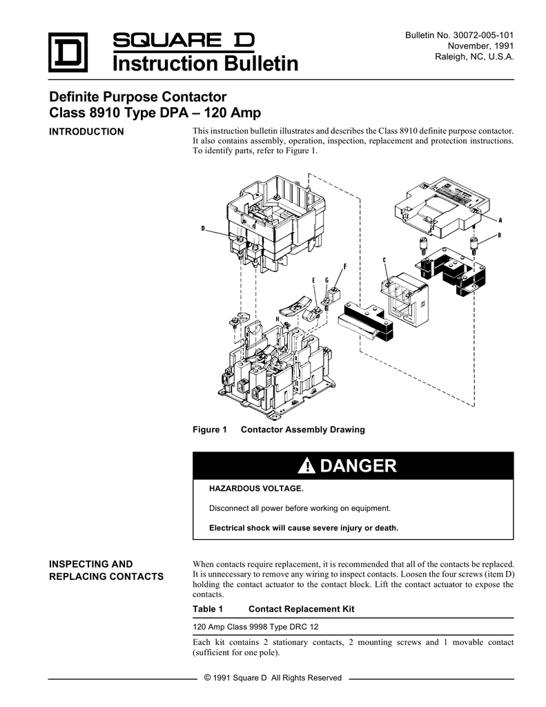
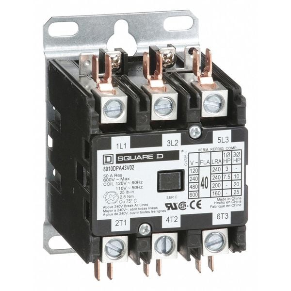
Definite Purpose Contactor, Class 8910 Type DPA
PDF Magnetic Contactors and Starters FC and FW series Definite purpose contactors and starters The FC series contactors are compact and economical contactors designed for use in Wiring A1 A2. Notes: • Other voltages are available in 24 to 600V ranges on request. • For frame size N1/SE to N4/SE, 24V to 250V AC (24V to 240V DC)...
C25BNB230A
How to Install a Definite Purpose Contactor | HomeSteady A definite purpose contactor is an automatic electrical control device that switches power on whenever it is necessary to start a motor to which it is connected. Check the wiring diagram supplied by the contactor manufacturer to determine which set of terminals to connect to the motor.
Definite purpose contactors and starters
PDF Definite Purpose Contactor Specifications | Wire Size 400 Definite Purpose Contactors. 20/25…40 FLA 1- and 2-Pole. Line and Load Terminals. #10-32 screw or box lug. Wire Size. The examples and diagrams in this manual are included solely for illustrative purposes. Because of the many variables and requirements associated with any particular...
Square D - 2 Pole, 20 Amp Inductive Load, Definite Purpose Contactor - 69524445 - MSC Industrial Supply
PDF Definite Purpose Control, catalog 8910CT9301 Definite Purpose Control. Contactors, Class 8910 Types DP and DPA. Table 4: 2 N.O. and 2 N.C. 4-Pole Contactors 600 Vac Maximum Above 240 V, all These kits include two jumper straps, a wiring diagram showing how to wire a three-phase starter to control a single-phase motor, and thermal unit...
C25DND230C
PDF Definite Purpose Contactors Definite Purpose Contactors. • Bulletin 400 Catalog Number Explanation. The Allen-Bradley Bulletin 400 Definite Purpose Contactors are specifically designed for applications such as Typical Wiring Diagrams — page 1-34 Accessories — page 1-93 Modifications — page 1-87 Specifications...
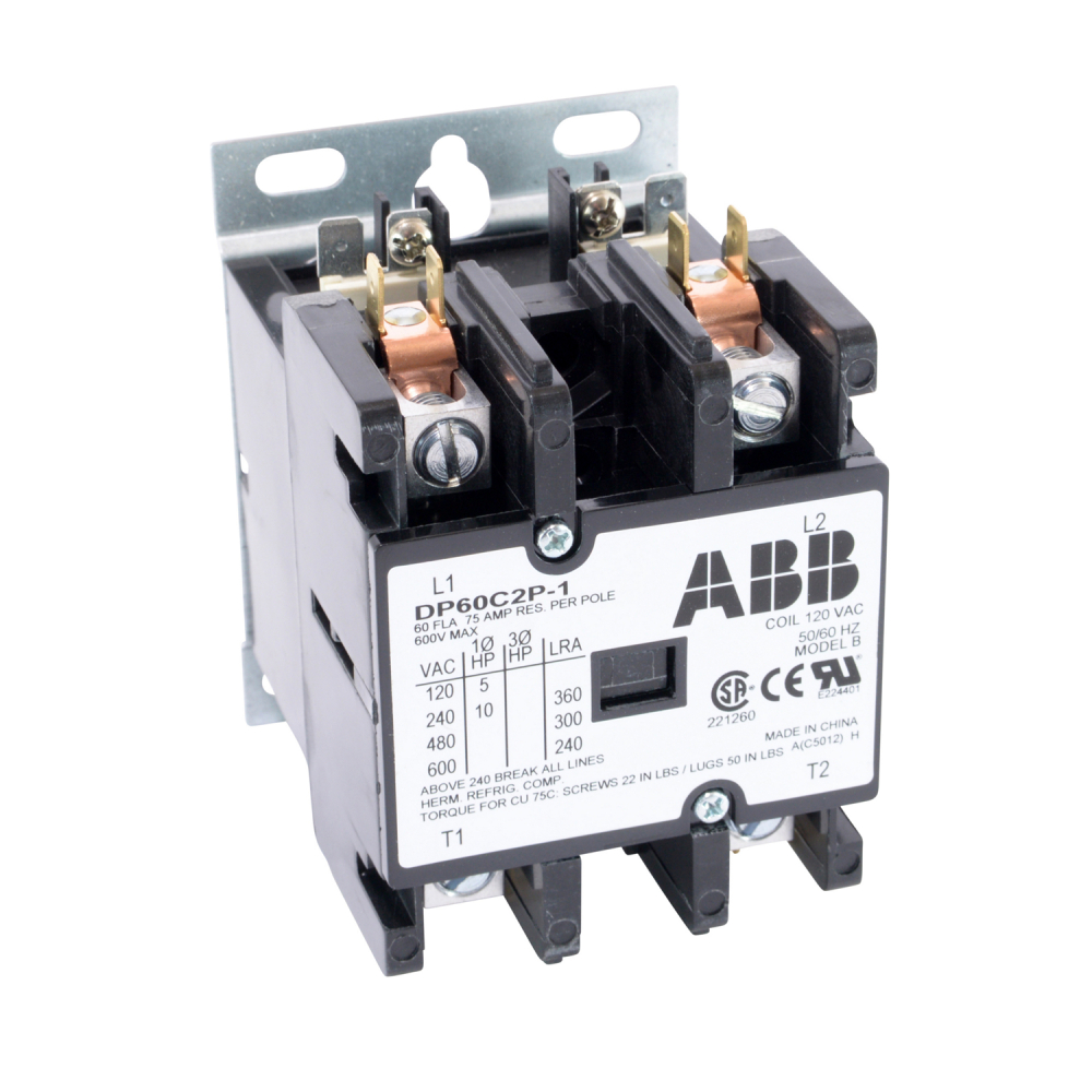
ABB, DP60C2P-1, 2 Pole, 60 Amps, 120VAC Coil, Definite Purpose Contactor
PDF Definite Purpose Control Definite Purpose Contactors Types DP, DPA and SYD — Class 8910. Denite purpose contactors are ideal for heating, air conditioning, refrigeration, data They feature quick connect terminals and binder head screws for easy wiring. Box lugs are standard on 40 ampere contactors and larger.

BDP3P40A277V Definite Purpose Contactor 3P 40A 600V max w/ 277V Control Coil NEW | eBay
PDF Definite Purpose Contactors l Definite Purpose Contactors l Switching up to 100A resistive, 90A inductive l Line Voltage up to 600VAC on most sizes l Control voltage up to 480VAC l Screw or box lug terminals available on most sizes l Fast-on coil and power terminal l Hp ratings on 3-pole contactors l UL recognized and CSA...
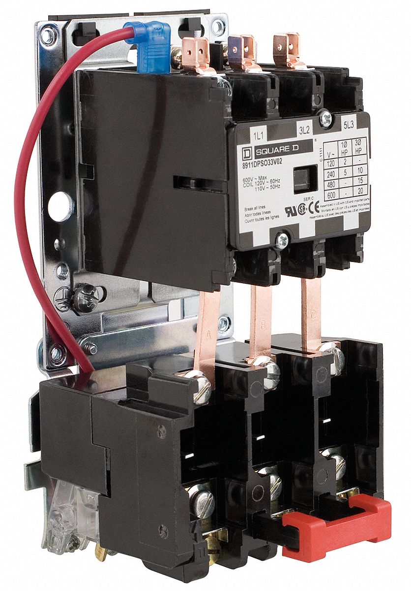
Definite Purpose Magnetic Motor Starter, Number of Poles 3, 30 A Amps AC, 120V AC Coil Volts
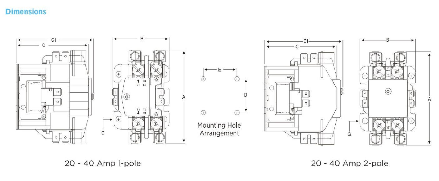
02 Contactors 12 Definite-purpose (DP) contactors are available. Consult Technical support for information; see contact. details on inside front cover. Dimensions pages 2-31 to 43. Wiring diagrams page 2-44. Technical characteristics page 2-48 to 69. 2 Contactors.
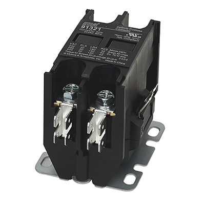
MARS 30A 2P 24V - 91321

DP20C2P-1-ABBG

Home
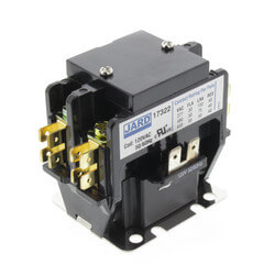
17326 - Jard 17326 - Jard 2 Pole Definite Purpose Contactor w ...
HCDP SERIES Definite Purpose Contactor - 2 POLE - HCDPY22440 ...
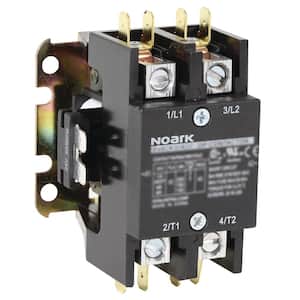
Noark 30 Amp 2-Pole Definite Purpose Contactor Ex9CK30A20U7 ...

Definite Purpose Contactors
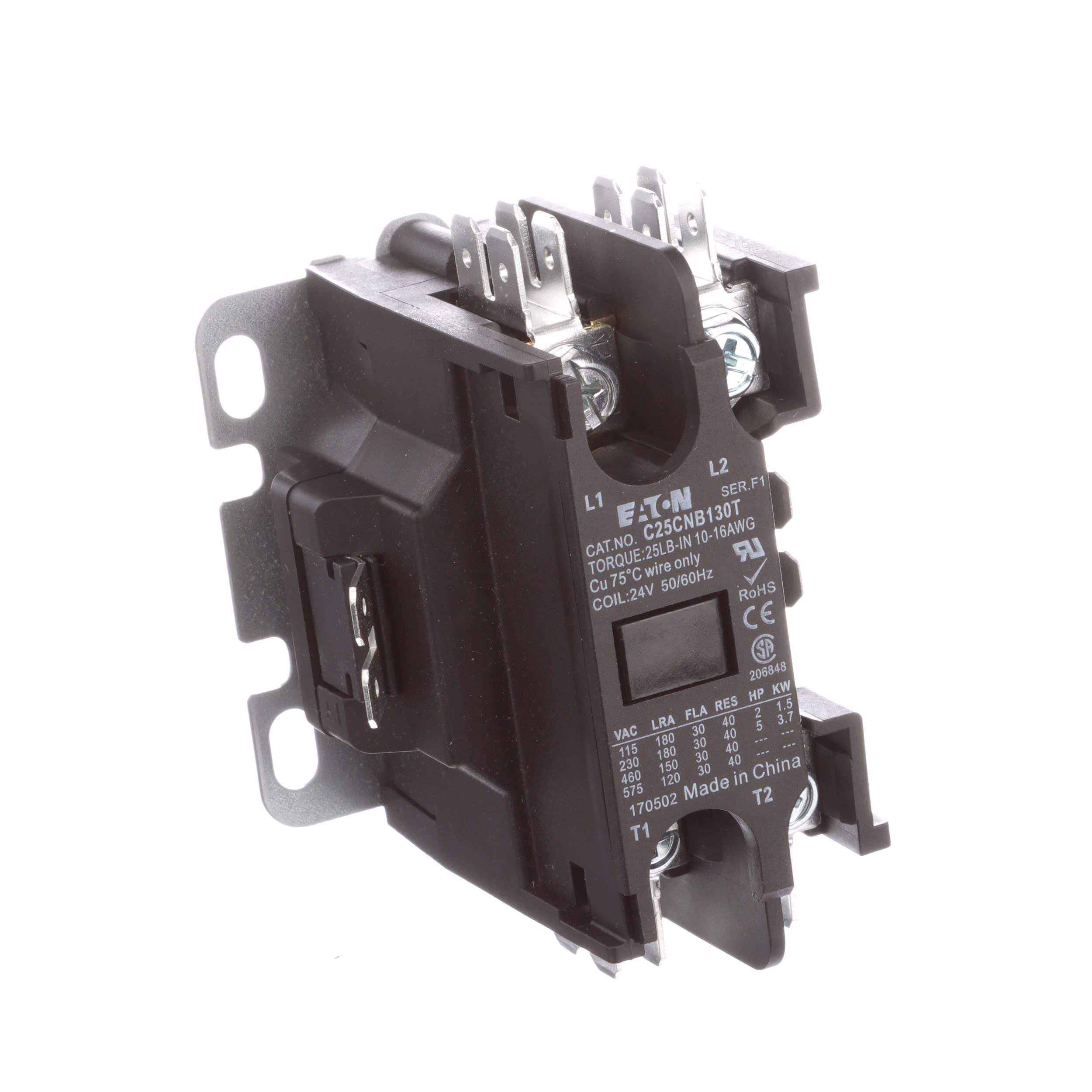
Eaton - Cutler Hammer - C25CNB130T - Contactors, Definite ...
NTE Electronics RLY400 Series Definite Purpose Contactors

Square-D-Mag-Starters

Yuco YC-CN-PBC202-7 Definite Purpose Contactor 20A 2P ...
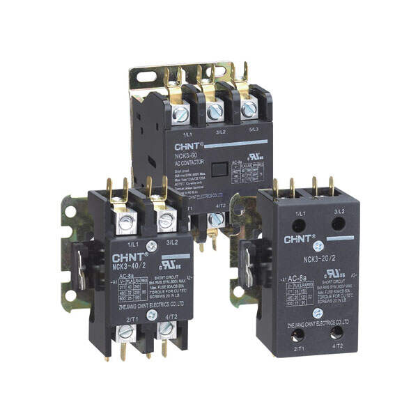
NCK3 Definite Purpose Contactor 20~90A | CHINT
What is a Contactor? | Library.AutomationDirect.com
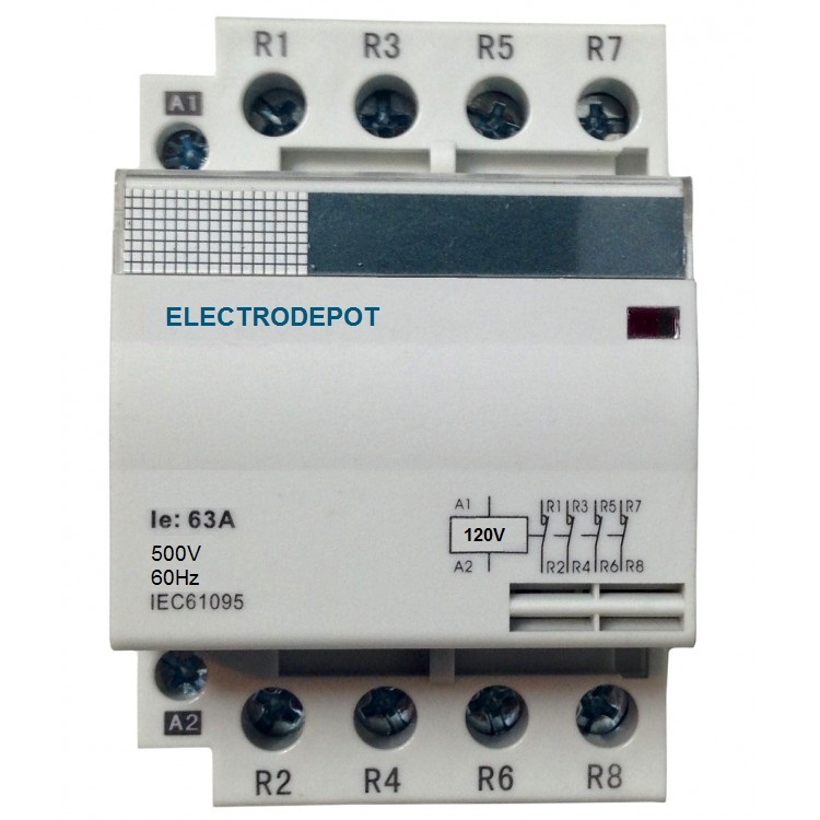
Lighting Contactor 30A 40A 50A 3, 4 pole Electrodepot
0 Response to "36 Definite Purpose Contactor Wiring Diagram"
Post a Comment