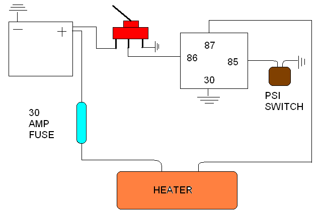
38 wet switch wiring diagram
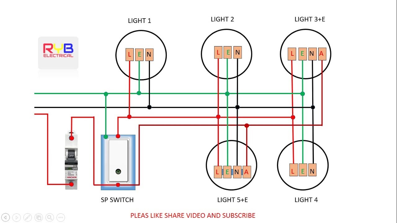
Figure 3.55ADAM-4055 Digital Output Wiring Diagram .....68 Figure 3.56ADAM-4055 Digital Input Dry Contact Wiring Diagram 68 Figure 3.57ADAM-4055 Digital Input Dry Contact Diagram (Inter-nal).....69 Figure 3.58ADAM-4055 Digital Input Wet Contact Wiring Diagram 69 02.01.2022 · Regardless of what 3-way switch wiring diagram, you’re following, you’ll need to use a 3-wire cable to connect the two 3-way light switches. So what you should see if you have the correct 3-wire electrical cable (Romex) is a black (power) white (neutral) and now a …
In the Trailer Wiring Diagram and Connector Application Chart below, use the first 5 pins, and ignore the rest. If your truck has a built-in 7-pin socket, but you only need 5 of the pins. Use the 7-pin connector anyway (see below), and just leave out the last 2 wires.

Wet switch wiring diagram
Wiring diagram for MSD RPM Switch . Limited Warranty: Nitrous Express (the warrantor) hereby warrants its product to the original purchaser thereof (the consumer) against any and all defects in workmanship and material under the following terms and conditions: The Limited Warranty is specifically limited to the original The diagram above is the 5 pin relay wiring diagram. There are different kinds of relays for different purposes. It can be used for various switching. Relay can be the best option to control electrical devices automatically. 5 pin is compromised of 3 main pins and an SPDT (single pole double throw). Wattstopper Occupancy Sensor Wiring Diagram. By Admin | October 21, 2017. 0 Comment. Legrand watt stopper dt 305 quick start manual pdf manualslib wattstopper pw 311 installation instructions power pack 120 277v 50 60hz 24vdc 225ma w auto on packs occupancy and vacancy sensors lighting controls systems lmrc 100 series digital switching room ...
Wet switch wiring diagram. 29.07.2018 · The Wall Connector can be set with an internal switch to work with 15 to 100-amp service. ... A circuit breaker protects your home from an electrical load that is beyond the capacity of the wiring or outlets. ... The most common answer is that it flows through something wet and then to the ground. This is why GFCIs are required on outlets used ... Wiring the AquaGuard® AG+ м Magnetic Float Switch. AG+ For wiring the normally open third wire (short wire) refer to the following diagrams. Where can I find a float switch wiring diagram? You asked, and today, we answer . Wiring a float switch isn't necessarily hard, but it can be a little confusing if you. Wet switch wiring diagram wiring diagram is a simplified suitable pictorial representation of an electrical circuitit shows the components of the circuit as simplified shapes and the knack and signal contacts in the midst of the devices. Lets start with the most basic float switch. Restore power to the system. Shop Vac Switch Wiring Diagram. Shop Vac Switch Wiring Diagram from d3nevzfk7ii3be.cloudfront.net. Print the wiring diagram off plus use highlighters to trace the signal. When you make use of your finger or perhaps the actual circuit with your eyes, it is easy to mistrace the circuit. 1 trick that We 2 to printing a similar wiring plan off twice.
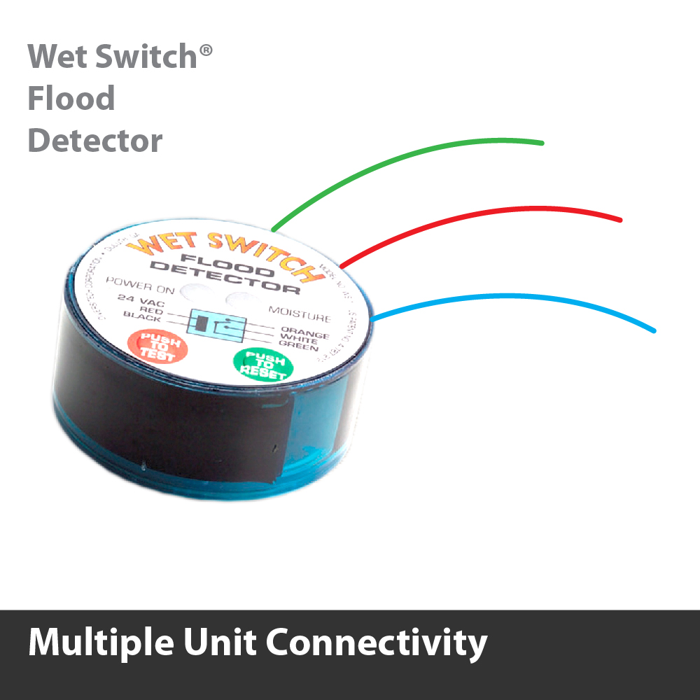
Trailer Wiring Diagrams Trailer Wiring Connectors Various connectors are available from four to seven pins that allow for the transfer of power for the lighting as well as auxiliary functions such as an electric trailer brake controller, backup lights, or a 12V power supply for a winch or interior trailer lights. f) Dual Air Pump with selector switch F. Seal failure relays shall be plug in pin type with indicator lights. G. Control wire to be MTW 90 degree C, #14 AWG. Color code and number all wiring as indicated on the factory-wiring diagram. All wiring shall be neatly grouped in plastic wire SAFE-T-SWITCH® SS610E WIRING DIAGRAM www.rectorseal.com. R50565-0320. 1. (Internal Installation) Place switch inside indoor unit enclosure or line set cover ... DiversiTech WS-1 - Wet Switch Flood Detector - The wet switch flood detector is a solid state control designed to help prevent flooding, damage to carpets, walls, furniture, ceilings, etc. It now has a built-in test and reset button for easier installation. It turns the system off when moisture due to condensate or drain leaks is detected.
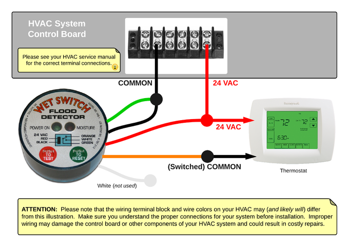
Tiffin Motorhome Wiring Diagram - tiffin allegro bus wiring diagram, tiffin allegro red wiring diagram, tiffin motorhome wiring diagram, Every electric structure is made up of various diverse components. Each part ought to be set and linked to other parts in specific way. Otherwise, the arrangement won't function as it should be. It is well engineered with a test switch and a clear wiring diagram on the nameplate. It comes with 6 ft of excellent sized wire. I just connected the wires to the 24 VAC control power in my system and it worked perfectly. Read more. 5.0 out of 5 stars Great Product 8. Disconnect power supply before making wiring connections to prevent electrical shock and equipment damage. 9. All appliances must be wired strictly in accordance with different from the wiring diagram could result in a hazard to persons and property. 10. Any original factory wiring that requires replacement must The wiring diagrams are very .Route the cable from the wet switch to cooling control voltage transformer as shown in the wiring diagram. Wire can be extended if necessary. Cut common wire of transformer. Connect black wire from wet switch to same wire on transformer where common was cut.
Wet Switch Wiring Diagram - Hanenhuusholli
Wet Location Touch Switch Input Module (WD0401) Wiring Diagrams : LSIM-P, LSIM-R, WTS : pdf LightLEEDer RS232/RS485 Serial Communications Module (WD1002) ... Wiring Diagrams : LSIM-P, LSIM-R : pdf Intelligent Lighting Controls, ILC. 5229 Edina Industrial Blvd. Edina, MN 55439. Phone 952.829.1900. ...
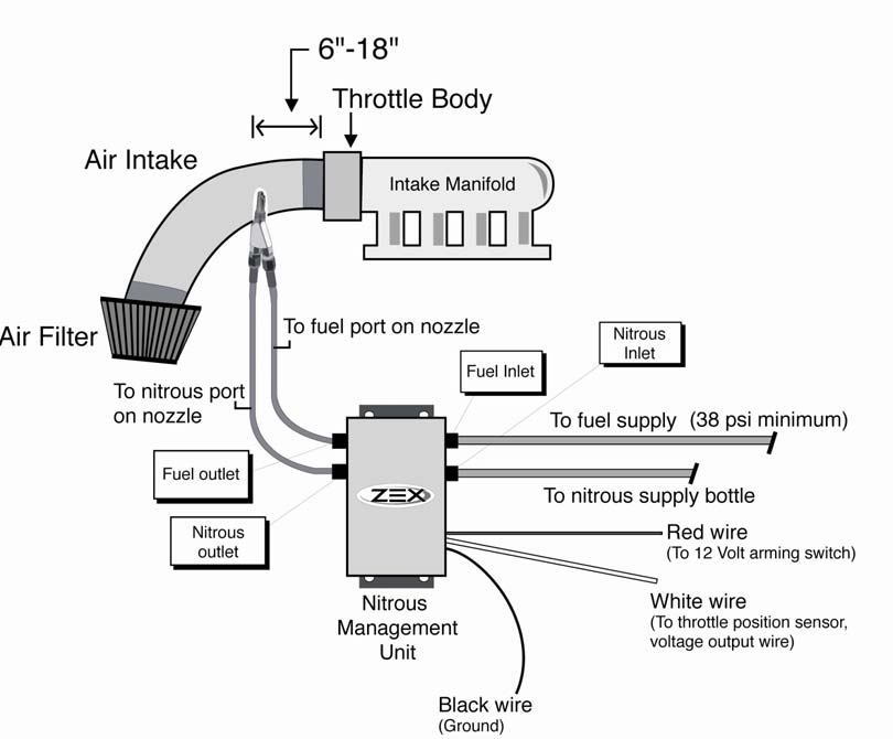
How to Install a Zex Wet Injected Nitrous System on Your ...
Wiring Diagrams of PLC and DCS Systems - DI, DO, AI, AO. by Editorial Staff. In this article, we are sharing the basic concepts of PLC and DCS control systems Wiring Diagrams for Digital Input (DI), Digital Output (DO), Analog Input (AI), and Analog Output (AO) signals.
Wiring Diagram For Photocell - RIAHSOSHI
Ansul System Wiring Diagram - ansul fire suppression system wiring diagram, ansul system micro switch wiring diagram, ansul system wiring diagram, Every electrical structure consists of various different components. Each part should be set and linked to other parts in specific manner. If not, the structure will not work as it should be.

Aquaguard Wet Switch Wiring Diagram - Search Best 4K ...
The best way to change the voltage on a motor is to follow the wiring diagram on the label. But sometimes when you open up a motor, there's just six wires and no diagram! This happened to be the case for the 1.5 hp motor on my old table saw . 20 years ago I wired it to 240 volts, but I wanted to switch it back to 120 volts. for where I moved it to.

Rainy Window
A. Connect “RED”, “Input 24 VAC (Hot)” and “Gray” “Common” wire of AG-4200E to 24 ... mended that a damp cloth be placed under the lines being brazed.5 pages

Wet Switch Wiring Diagram - flilpfloppinthrough
Never operate it in a wet environment. ... L-H pin wiring b) H-pin wiring c) L-pin wiring d) Isolated remote on-off cable Figure 3: Remote on/off connections ... Figure 4: Engine shutdown detection override connection diagram If the ignition switch in figure 4 is switched off, the charger will return to “engine shutdown detection” mode, it ...

Aquaguard Wet Switch Wiring Diagram - Search Best 4K ...
1. Turn o power to the system. · 2. Place Wet Switch, padded side down, on the surface to be monitored. · 3. Connect wiring as shown in the diagrams on page 2.

Hayward Universal ColorLogic LED Standard Switched Spa ...
04.01.2022 · The two wiring diagrams above are of a 3-way switch setup and the same basic setup with a 4 way light switch added. While the physical location of the 4 way switch may be anywhere, the electrical location of the switch is always between the two 3 way switches.

Umbrellas in a busy street
Do not wear damp clothing (particularly wet shoes) or allow skin surface to be damp when handling electrical equipment. • Use extreme caution when working on electri-cal components. High voltages can cause inju-ry or death. DO NOT tamper with interlocks. • Follow all applicable state and local electrical codes. Have all electrical ...

WS-1 - DiversiTech WS-1 - Wet Switch Flood Detector
3 way switch common wire color. 3-way switches are used any time that you want two switches to operate one light or lights. 3-Way Switch Wiring Diagram NM Cable A very common type of 3-way electrical diagram is when the power supply wire moves from one switch to the second switch and finally terminates at the fixture. Make a J-hook in the wire ...
Diversitech Wet Switch Wiring Diagram
WIRING IT INTO THE RED CIRCUIT OR ANY OTHER CIRCUIT COULD RESULT IN PRODUCT OR SYSTEM MALFUNC- TION. 1. Power system off. 2. Cut one wire going to the compressor contactor. 3. Connect SOS Switch wires to the cut ends and install wire nuts. 4. With SOS Switch away from tubing, turn system on. 5. Compressor should operate normally. 6.
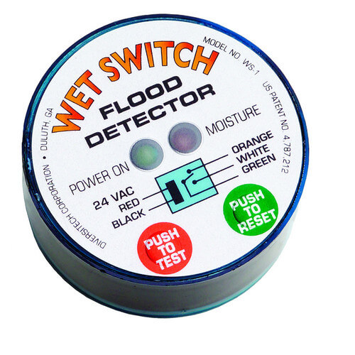
WS-1 - DiversiTech WS-1 - Wet Switch Flood Detector
These Wiring Diagrams will help you wire up your Nitrous System or Nitrous Accessory. Includes Nitrous Purge, Nitrous Bottle Heater, and Dedicated Fuel System. ... Wet Powersports Wiring Diagram. ... Switch Panel Wiring Diagrams.
Diversitech Wet Switch Wiring Diagram - PRINCESSBLACK247
Dewalt dcv581h 18v nicd 20 v max li ion 2 gallon corded cordless wet dry vacuum. Typically it uses black green white and red cable colors. The dewalt wiring diagrams professional reference is a must for anyone who installs or replaces electrical wiring. Black cable serves as floor just like in every other apparatus.
Shop Vac Switch Wiring Diagram - Hanenhuusholli
Wet Sounds' marine stereo systems and equipment provide crisp, high-quality audio that's loud enough to be heard whether you're fishing a local pond, water skiing on a lake, or tubing on the ocean. Enjoy unparalleled protection from water damage with Wet Sounds' state-of-the-art equipment.
Diversitech Wet Switch Wiring Diagram
7 Pin Ignition Module Wiring Diagram - wiring diagram is a simplified satisfactory pictorial representation of an electrical circuit. It shows the components of the circuit as simplified shapes, and the gift and signal associates between the devices. A wiring diagram usually gives opinion virtually the relative aim and concord of devices and ...

Diversitech Wiring Diagram
Place Wet Switch, padded side down, on the surface to be monitored. 3. Connect wiring as shown in the diagrams on page 2. Wires may be extended as necessary, but avoid excess run lengths. 4. Restore power to the system. Controlling Selected Components System components such as compressors, electric valves, condenser Model No. WS-1 WET SWITCH ...
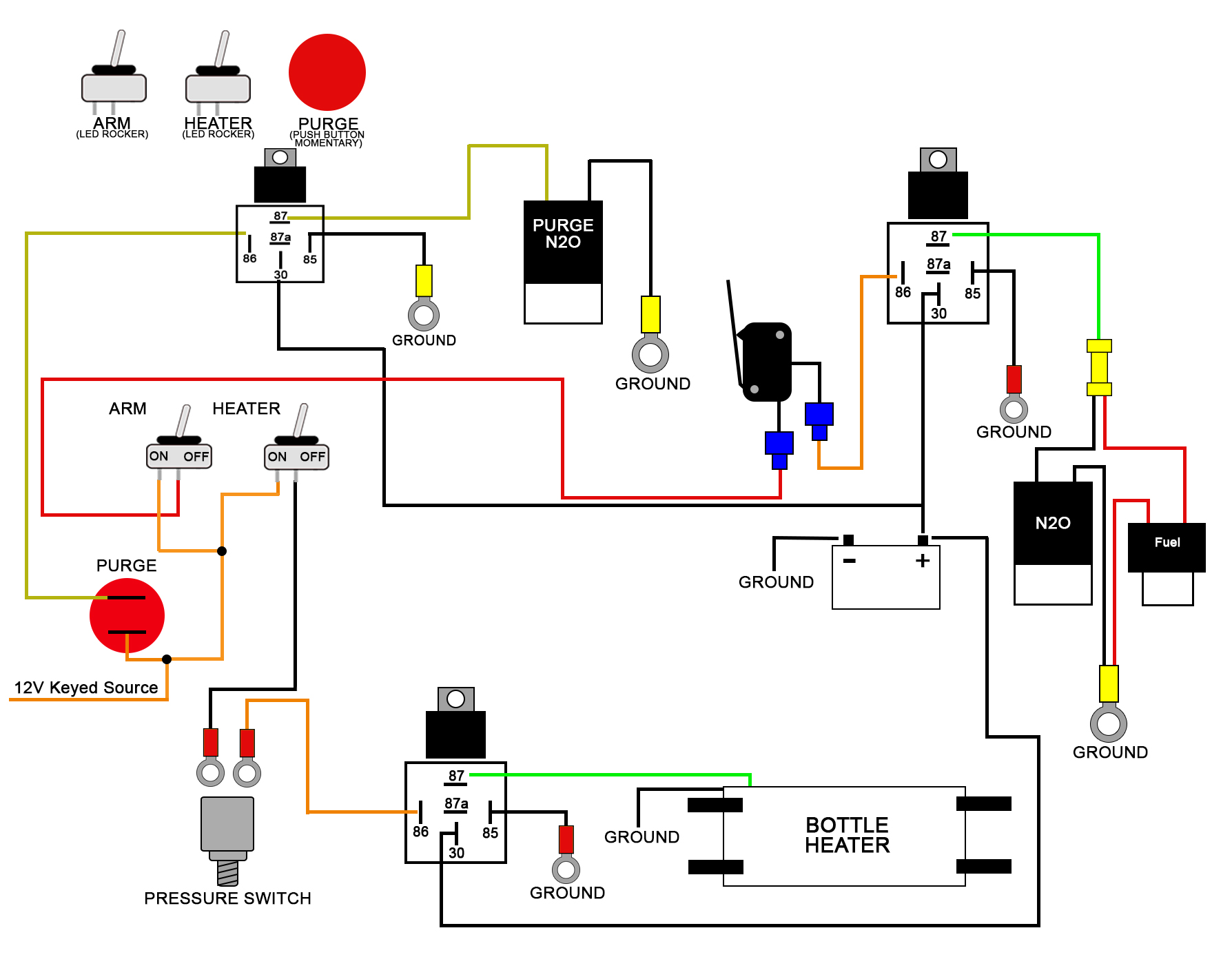
Wiring window switch to nitrous kit - LS1TECH
Potter Vsr Flow Switch Wiring Diagram. The Model VSR is a vane type waterflow switch for use on wet sprinkler systems. It is UL The switches are actuated when a flow of 10 GPM (38 LPM) or more occurs . Break out thin section of cover when wiring both switches from one. The Model VSR is a vane type waterflow switch for use on wet sprinkler systems.

Honeywell Lyric Thermostat Wiring Diagram - WIRGRAM
Wet Switch Wiring Diagram– wiring diagram is a simplified suitable pictorial representation of an electrical circuit.It shows the components of the circuit as simplified shapes, and the knack and signal contacts in the midst of the devices.
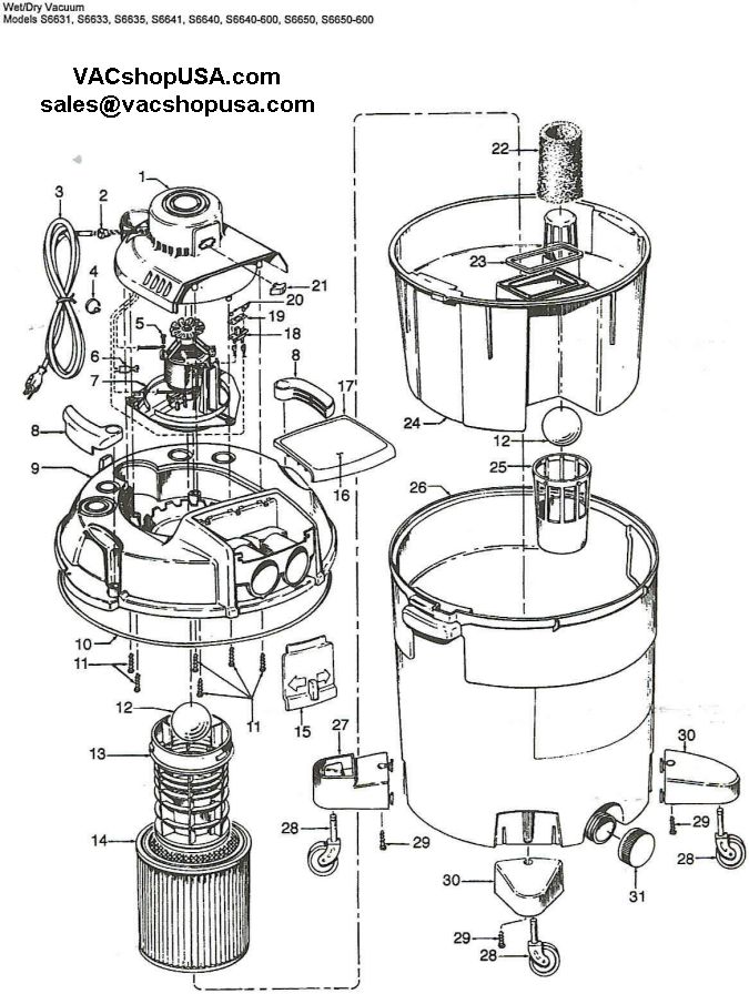
Hoover Wet Dry Vacuum Part Schematic
Wiring design systems can become confusing when some switching devices send power to the load automatically while others do not. Often called 'wet' and 'dry' contacts, these devices are fairly easy to troubleshoot once the differences are understood.

Ebike Throttle Wiring Diagram : Power Switch Circuit For ...
Place the wet switch with the padded side down on the surface to be monitored. Route the cable from the wet switch to cooling control voltage transformer as shown in the wiring diagram. Wire can be extended if necessary. Cut common wire of transformer. Connect black wire from wet switch to same wire on transformer where common was cut.

Kenmore Pressure Switch wet when Inducer Off ...
08.01.2018 · Use our handy classic Mini parts diagram to find the right part for your favorite little car. This is the 1959-1989 parts diagram by Mini Mania.

Wiring Diagram For Wet Underfloor Heating - Wiring Diagram ...
Wiring diagram-Daikin. Wiring diagram-Panasonic. Wiring diagram-LG. Wiring diagram-Samsung. Wiring diagram-Quietsite. Wiring diagram-Fujitsu. Wiring diagram- Mitsubishi. Wiring diagram- Friedrich. Wiring diagram- Gree. Wiring diagram- SOLEUSAIR. Wiring diagram- Haier. Wiring diagram- Lennox. Wiring diagram- American Standard. Wiring diagram ...

Wet Switch Wiring Diagram - Hanenhuusholli
Feb 1, 2005 — Re-apply power. Wet Switch Schematic. 24 VAC. RED. BLACK. ORANGE. WHITE. GREEN t-stat circuit board or controls. CUT COMMON WIRE*.

31 Shop Vac Switch Wiring Diagram - Wiring Diagram Database
There are no good videos on YouTube for installing this accessories so I made my own and thought I would share! Wet switch installation.

Wiring Diagram For Wet Underfloor Heating - Wiring Diagram ...
Let’s start with the most basic float switch: a two-wire, single-pole, single-throw float switch.The rising action of the float can either close (i.e., turn on) a “Normally Open” circuit, or it can open (turn off) a “Normally Closed” circuit.Installation scenarios might include a Normally Open float switch turning on a pump to empty a tank (Control Schematic 2), or a Normally Closed ...

27 Sauna Heater Wiring Diagram - Wiring Diagram List
Connection showing two or more Wet Switches in series ... transformer as shown in the wiring diagram. Wire can be extended.

Leviton Gfci Outlet Wiring Diagram / Installing Switch And ...
INSTALLATION WIRING DIAGRAM ... (NO) trigger input and provides one (1) Fused 2 Amp SPDT Output (jumper selectable Wet or Dry) and one (1) Non-fused Dry (2 Amp) SPDT output (jumper selectable Wet or Dry). Closing a switch across the Dry Trigger Input for Station A, B, C or D will release the output for the amount of time that the trigger input ...

31 Shop Vac Switch Wiring Diagram - Wiring Diagram Database
DiversiTech WS-1 Wet Switch Flood Detector Double Throw Relay-Allows for wiring to interrupt system and to sound an alarm (by others) when moisture is detected; The Wet Switch is designed to interrupt the operation of cooling systems. However, it is a water activated switch and can be used in a variety of other applications /5 (42).
Nos Bottle Warmer Wiring Diagram - Best Pictures and ...
Wet sounds sound Bar Wiring Diagram wiring diagram is a simplified good enough pictorial representation of an electrical circuit. ... 3 Way Switch Wiring Diagram Home Electrical Wiring House Wiring Electrical Wiring . Universal 6 Speaker All Weather Sound Bar With Bluetooth Sound Bar Speaker Power Amplifiers .

Water Tank Wiring Diagram : Wiring Diagram Water Heating ...
Wattstopper Occupancy Sensor Wiring Diagram. By Admin | October 21, 2017. 0 Comment. Legrand watt stopper dt 305 quick start manual pdf manualslib wattstopper pw 311 installation instructions power pack 120 277v 50 60hz 24vdc 225ma w auto on packs occupancy and vacancy sensors lighting controls systems lmrc 100 series digital switching room ...

Wet Switch Wiring Diagram - flilpfloppinthrough
The diagram above is the 5 pin relay wiring diagram. There are different kinds of relays for different purposes. It can be used for various switching. Relay can be the best option to control electrical devices automatically. 5 pin is compromised of 3 main pins and an SPDT (single pole double throw).

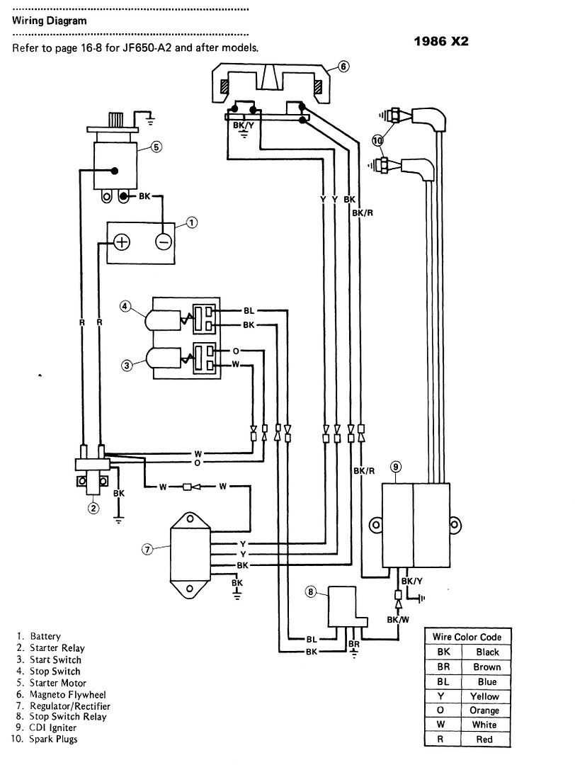
My 4400 engine shuts down when shifting into forward and ...
Wiring diagram for MSD RPM Switch . Limited Warranty: Nitrous Express (the warrantor) hereby warrants its product to the original purchaser thereof (the consumer) against any and all defects in workmanship and material under the following terms and conditions: The Limited Warranty is specifically limited to the original

Wet Switch Wiring Diagram - Hanenhuusholli

55 Ansul Micro Switch Wiring Diagram - Wiring Diagram Harness

Shop Vac Switch Wiring Diagram - Drivenheisenberg

NYC Winter

Sump Pump Wiring Diagram / Diagram Sump Pump Wiring ...

Instagram: @Jord.in
0 Response to "38 wet switch wiring diagram"
Post a Comment