36 natural gas plant process flow diagram
Natural gas was discovered accidentally in ancient China, as it resulted from the drilling for brines.Natural gas was first used by the Chinese in about 500 BC (possibly even 1000 BC).They discovered a way to transport gas seeping from the ground in crude pipelines of bamboo to where it was used to boil salt water to extract the salt in the Ziliujing District of Sichuan. Browse process flow diagram templates and examples you can make with SmartDraw.
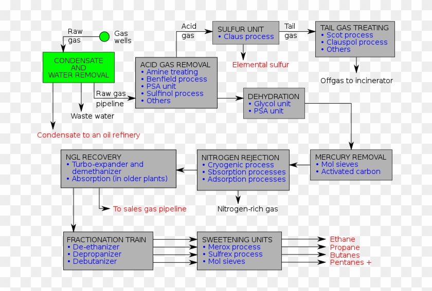
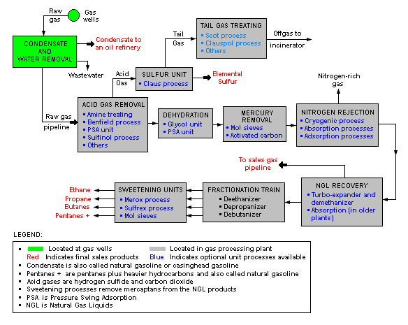
There are a great many ways in which to configure the various unit processes used in the processing of raw natural gas. The block flow diagram below is a ...

Natural gas plant process flow diagram
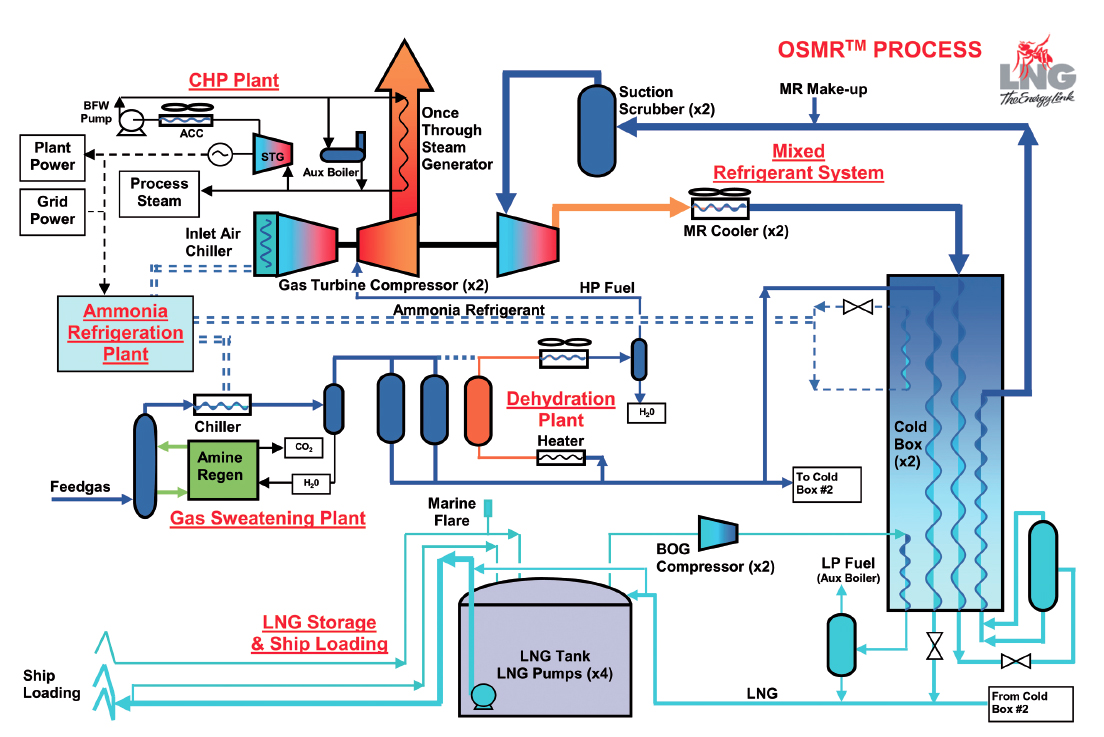
Natural Gas Industry Process Flow Diagram. Create Process Flow Diagram examples like this template called Natural Gas Industry Process Flow Diagram that you can easily edit and customize in minutes. 1/16 EXAMPLES. Natural gas power plants generate electricity by burning natural gas as their fuel.There are many types of natural gas power plants which all generate electricity, but serve different purposes. All natural gas plants use a gas turbine; natural gas is added, along with a stream of air, which combusts and expands through this turbine causing a generator to spin a magnet, making … Figure 5.3-2. Flow diagram of the amine process for gas sweetening. 5.3.3 Emissions4-5 Emissions will result from gas sweetening plants only if the acid waste gas from the amine process is flared or incinerated. Most often, the acid waste gas is used as a feedstock in nearby sulfur recovery or sulfuric acid plants.
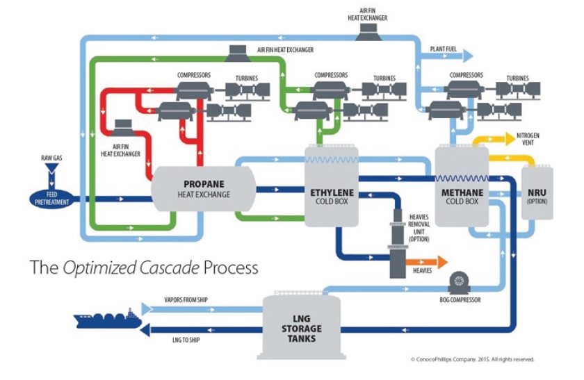
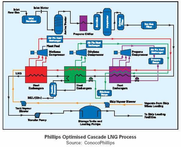
Natural gas plant process flow diagram. Typical Block Diagram - Liquefaction Plant DEHYDRATION & MERCURY REMOVAL CHILLING LIQUEFACTION NITROGEN REJECTION REFRIGERATION SYSTEM REFRIGERATION SYSTEM OFFSITE LNG STORAGE HYDROCARBON FRACTIONATION NATURAL GAS FEED C2 FUEL FUEL LNGCO C3 C4 BY PRODUCT GASOLINE C2 C4 2 REMOVAL. Typical … 03.07.2012 · The process flow diagram (PFD) represents a quantum step up from the BFD in terms of the amount of information that it contains. The PFD contains the bulk of the chemical engineering data necessary for the design of a chemical process. For all of the diagrams discussed in this chapter, there are no universally accepted standards. The PFD from one … Natural gas processing plants are used to purify the rawnatural gas extracted ... block flow diagram below is a generalized, typical configuration for the ...4 pages As a substitute for fossil natural gas, has many RNG potential uses. RNG can be used vehicle fuel, to as generate electricity, in thermal applications, or as a bio-product feedstock. RNG can be injected into natural gas transmission or distribution pipelines, or it can be used locally (i.e., at or near the site where the gas is created).
01.03.2015 · One of the initial steps to creating a process flow diagram is to add all of the equipment that is in the plant. Not only is the major equipment, such as distillation columns, reactors, and tanks, necessary to be shown in a PFD, so is the equipment such as the heat exchangers, the pumps, reactors, mixers, etc). The following figures will display the most … Natural Gas Feeds . Recycle Feeds . Oxidizer Feeds . Product Feeds . Fuel Burning Equipment . Thermal Oxidizer . Figure C -1: Ethane Cracker Process Flow Diagram . ... Polyethylene Plant A Process Flow Diagram Product Feeds Vent Streams Recycle Feeds Flare Feeds Fuel Burning Equipment PM Pollution Control Devices POLYMERIZATION PA-PE-202 ... Historically, you can find references to natural gas dating back to 1,000 B.C.. With advances in technology . the U.S. currently has an estimated 100-year supply of shale gas. The process of liquefying natural gas is comparatively new and was only discovered in 1820. The first LNG plant was built in 1912 and LNG shipping began around 1959. A.5 – Simplified Flow Diagram of a Typical Natural Gas Straddle Plant (without Fractionation). 22. 23. A.6 – Alberta Gas Processing Index Weighting Factors.15 pages
Natural Gas. CO. 2 /H. 2. S Removal. Dehydration. Heavy Component Removal. Natural Gas Liquefaction. Transportation. Flow Diagram for a Typical LNG Plant Download scientific diagram | Natural gas process flow diagram. from publication: Improving NGL recovery process with dividing-wall column for offshore ... A generalized natural gas flow diagram is shown in Figure 12.2 [7]. After initial scrubbing to remove particles, the first step in natural gas processing is the removal of condensate (oil) and water that is achieved by controlling the temperature and pressure of the inlet stream from the well, as shown in Figure 12.4. Bijan Elahi, in Safety Risk Management for Medical Devices, 2018. 12.7.1.3 Process Flow Diagram. Process Flow Diagrams (PFDs) are a graphical way of describing a process, its constituent tasks, and their sequence. A PFD helps with the brainstorming and communication of the process design. The PFMEA process needs a complete list of tasks that comprise the …

Highspeedâ„¢ Gas Dehydration | Kirk Process
xiv Plant Processing of Natural Gas J.C. Kuo (Chen Chuan J. Kuo) is a 34-year veteran of the gas process-ing, gas treating, and liquefied natural gas (LNG) industry. As a senior advisor for Chevron’s Energy Technology Company, he has served as the Process Manager/ Process Lead for many projects, including the Wheatstone LNG, Gorgon

Simple cycle gas plant - Energy Education
13.03.2015 · The plant is proposed to be located in Freeport, Texas to be near the East Texas Basin natural gas feedstock. It will be able to produce the hydrogen at 100 MMscfd (Million standard cubic feet per day), a relatively high capacity plant especially for such high purity hydrogen. In addition to the feedstock, the location also has a low corporate tax rate reducing …

A process flow diagram (PFD) is commonly used by engineers ...
In Handbook of Liquefied Natural Gas, 2014. 7.4. LNG plant startup. The following is a general guideline for the startup for an LNG production plant. A generic C3MCR liquefaction train process flow diagram is shown in Figure 7-2. Startup of other liquefaction technologies may be slightly different.

LNG (liquefied natural gas) satellite station | Energy ...
Apr 10, 2014 - A process flow diagram (PFD) is commonly used by engineers in natural gas processing plants, petrochemical and chemical plants, ...
Natural gas production processing transport pdf
In this Video we have covered the followingGas Processing Plant Process Flow DiagramGas Processing Plant Process EquipmentsGas Processing Plant Process Equip...

Succulent Frenzy
Natural-gas processing is a range of industrial processes designed to purify raw natural gas by removing impurities, contaminants and higher molecular mass hydrocarbons to produce what is known as pipeline quality dry natural gas.. Natural-gas processing begins at the well head. The composition of the raw natural gas extracted from producing wells depends on the type, …

Electric Generation - cdohertycrestin
Figure 5.3-2. Flow diagram of the amine process for gas sweetening. 5.3.3 Emissions4-5 Emissions will result from gas sweetening plants only if the acid waste gas from the amine process is flared or incinerated. Most often, the acid waste gas is used as a feedstock in nearby sulfur recovery or sulfuric acid plants.

32 Oil And Gas Production Process Flow Diagram - Free ...
Natural gas power plants generate electricity by burning natural gas as their fuel.There are many types of natural gas power plants which all generate electricity, but serve different purposes. All natural gas plants use a gas turbine; natural gas is added, along with a stream of air, which combusts and expands through this turbine causing a generator to spin a magnet, making …
Schematic Flow Diagram Of A Typical Natural Gas Processing ...
Natural Gas Industry Process Flow Diagram. Create Process Flow Diagram examples like this template called Natural Gas Industry Process Flow Diagram that you can easily edit and customize in minutes. 1/16 EXAMPLES.

Flow diagram of the Haradh Gas Processing Plant ...
Natural gas processing - encyclopedia article - Citizendium

Cryogenic Plants | Joule Processing
liquefaction on emaze
Oil And Gas Production Process Flow Diagram - Wiring Diagram

Simplified process flow diagram of the pyrolysis plant ...

The Process Flow Diagram (PFD) of the hydrogen liquefier ...

Natural Gas Power Plant Process Flow Diagram - Aflam-Neeeak

Monochrome, Power Lines, Winlaton Mill, Tyne & Wear, England.

I am really happy when you use my pics, but also it is really nice simply to know about it. Please, send me DM or e-mail with the link, tag me in Instagram @alexblock or Facebook @alexblocktravels. I will be happy to see it and share your material in my social media. If you would love to use it at your web site, i would really appreciate if you will credit me there by putting link to my alexblocktravels.com. It really matters and helps bringing more beautiful pics! Thank you and have a great day!
Process Flow Diagram Lng - Trusted Wiring Diagrams

Natural gas processing - encyclopedia article - Citizendium
Assessing the Natural Gas Processing Market - Emerson ...
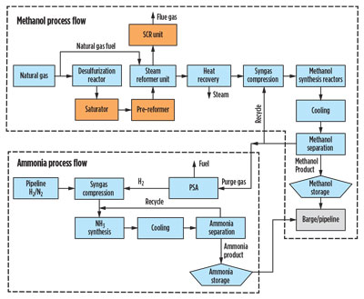
Process design overview for upgrading a gas-to-methanol ...
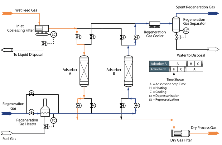
Adsorption Dehydration: Two-Tower vs Three-Tower System ...

Water, Steam and Fuel Gas flow diagram of Steam Power ...

Dracaena
Toprak Home Page

Monochrome, Tree Silhouette, Dunoon, Argyll & Bute, Scotland.

Sir Isaac Lowthian Bell Bt F.R.S. (1816-1904) Glass slide in Dorman Museum Collection.

Leaf with glass water

Simulated Natural Gas Combined Cycle (NGCC) power plant ...

Process flow diagram of the two-stage acid gas treatment ...

Procurement Resource Analyses The Production Cost Of Acetylene In Its New Report
System Support Engineering Framework: A Tool to Achieve ...

Natural Gas Power Plant Process Flow Diagram - Aflam-Neeeak

Process flow diagram methanol-to-olefins process [13,14 ...
0 Response to "36 natural gas plant process flow diagram"
Post a Comment