38 intellitec battery disconnect relay wiring diagram
Intellitec SERVICE MANUAL ISOLATOR RELAY DELAY/E Isolator Relay Delay/E P/N 00-00629-120 (12V) P/N 00-00629-240 (24V) CAUTION: The Isolator Relay Delay/E controls the Isolator Relay which is connected directly to the chassis and coach batteries. Power from both the batteries is fed into the module. The full power of the battery is ... Mission Statement: Supporting thoughtful exchange of knowledge, values and experience among RV enthusiasts. Need a bit more help with our Intellitec 00-00524-100 Battery Control Center components.*. I'm kinda confused when comparing the solenoids in ours with the parts shown in the Service Manual.*.
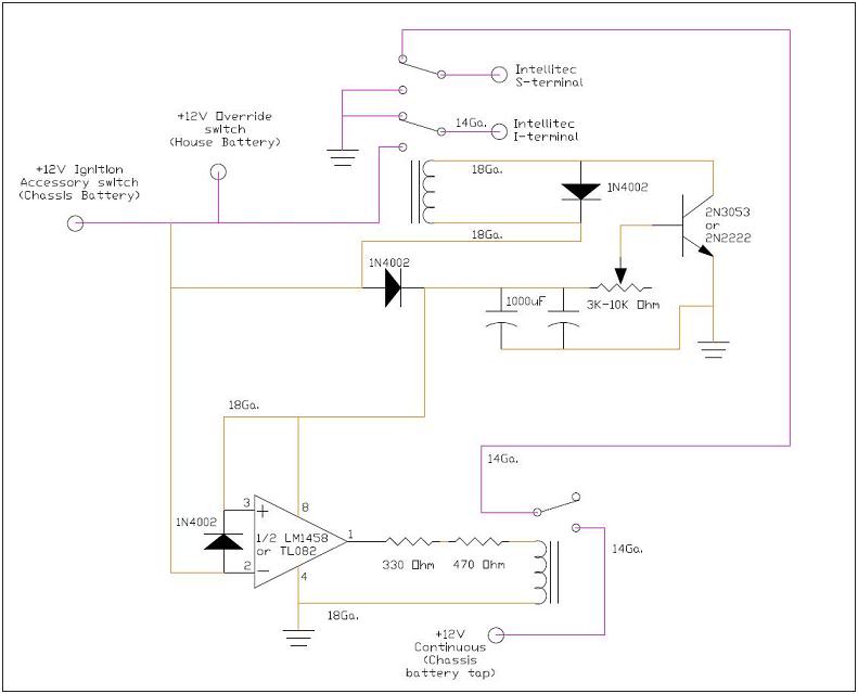
Jul 12, 2017 · Intellitec P/N Rs232 Programming Adaptor 00-00849-000 This wire drives the BD Relay ‘I’ terminal at a positive potential for a short period of time to perform a disconnect. This wire is internally connected to negative when it is OFF. This negative provides the return current path for when BD Relay ‘S’ is energised to perform a reconnect.

Intellitec battery disconnect relay wiring diagram
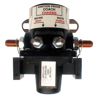
Jan 26, 2019 · Intellitec Battery Disconnect Relay Wiring Diagram. Variety of intellitec battery disconnect relay wiring diagram. A wiring diagram is a streamlined conventional pictorial depiction of an electrical circuit. It reveals the parts of the circuit as simplified shapes, and the power and signal links between the gadgets. A wiring diagram usually offers details concerning the loved one… Intellitec Battery Disconnect Wiring Diagram. There is a heavy wire going from each of the battery disconnect solenoids going to that emergency start . Single & Dual wiring diagram here. The Battery Disconnect Relay is a mechanically latching switch that operates by the momentary application extreme caution when working with these wires. 1485 Jacobs Rd. Deland, FL 32724 386.738.7307 / 1.800.251.2408 www.intellitec.com P/N 53-00066-100 Rev. C 111716 Intellitec SERVICE MANUAL BATTERY DISCONNECT To open the relay, +12 volts is applied to the "S" terminal and ground on the "I" terminal.
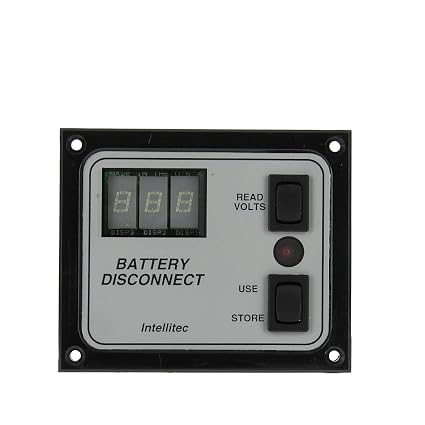
Intellitec battery disconnect relay wiring diagram. The 200 amp battery disconnect system includes 1x 200A battery disconnect relay, 25 ft. of cable, battery disconnect monitor panel with voltage reading, and ignition interlock to prevent disconnection while engine is running. Specifications: Kit includes: 1x 00-01090-100 Battery disconnect panel 1x 00-00507-012 Big boy 12V battery guard relay 200A Intellitec Battery Control Center. Hi all, ... between pins 1 and 2 to ensure that the coach wiring and relay coil are not damaged. With the relay pulled in, there should be zero volts across the load ... "Necessary conditions are: coach battery disconnect engaged, shore power on, converter operating, and coach battery ... Variety of intellitec battery disconnect relay wiring diagram. In order to make sure the electric circuit is built. As in the diagram a wire is run from a 12 volt power source to the switch in the cab and out to the relay placing a fuse at the source of the power. Problem with relay I think or Panel. I have the Intellitec 01-00066-003 BD3 switch panel and the Intellitec 01-00055-000 Battery disconnect relay. Problem: switch will not turn chassis off coach works turns battery relay on and off but chassis does not so I tried an idea.I unhooked the wires that...
Intellitec Battery Disconnect Relay Wiring Diagram. schematron.org Intellitec. SERVICE MANUAL. BATTERY DISCONNECT. FIGURE 1. Relay Closing A typical circuits is shown in FIGURE 5 and FIGURE 6. The Battery Disconnect Relay is a mechanically latching switch that operates by the momentary A typical circuits is shown in FIGURE 5 and FIGURE 6. I ... I was standing there this morning trying figure out the wires with all these various diagrams and suddenly I wondered why I have four heavy wires on the positive pole of the coach battery pair, see attached pic. One wire connects the two batteries in parallel together, one wire runs up to the battery disconnect relay, one wire runs to the HWH ... May 25, 2018 · intellitec battery disconnect relay wiring diagram – What’s Wiring Diagram? A wiring diagram is a type of schematic which uses abstract pictorial symbols to show every one of the interconnections of components in the system. 131 Eisenhower Lane North Lombard, IL 60148 630.268.0010 / 1.800.251.2408 www.intellitec.com P/N 53-00066-100 Rev. B 030905 Intellitec SERVICE MANUAL BATTERY DISCONNECT To open the relay, +12 volts is applied to the S terminal and ground on the I terminal.
The Battery Disconnect is designed incorporating Intellitec's patent No. 4,628,289, of a simple magnetic mechanism. It operates as a latching relay, drawing current to keep it closed or open. This latching feature allows the Disconnect to operate without dischargingthebattery. To close the Disconnect, a positive voltage is applied 0 1 021 $ , - $ $ 2 3 4 %5* If your BATTERY DISCONNECT is for a two battery system, repeat the relay mounting and battery cable instructions for the coach (auxiliary) battery. If the relays cannot be mounted close enough together for the Control Cable to reach, an 18 gauge wire may be spliced into the cable to lengthen it. Mar 18, 2018 · Size: 196.10 KB. Dimension: 600 x 315. DOWNLOAD. Wiring Diagram Pictures Detail: Name: intellitec battery disconnect relay wiring diagram – Notice it only uses two wires and it s called a "Pulsing" relay Pulse once and it changes from to f or f to The Intellitec and maybe that other. File Type: JPG.
55 Unique Intellitec Battery Disconnect Relay Wiring Diagram. 55 Unique Intellitec Battery Disconnect Relay Wiring Diagram- A manage relay is used in the automotive industry to restrict and regulate the flow of electricity to various electrical parts inside the automobile. They permit a little circuit to direct a unconventional flow circuit ...
By passing the coach battery disconnect relay , SHOULD have no effect on the coach running, but with some one playing around with wiring , anything is possible. Thanks Skip426! It looked to me like the fuse in question didn't hook into the hot side of the board, but rather grabbed power from the terminal in the bottom for the box, fused it, and ...
Intellitec battery disconnect wiring further winnebago motorhome wiring diagram moreover damon ultrasport wiring diagram further jayco greyhawk wiring diagrams as well as wiring diagram for fleetwood mobile home in addition kib electronics battery disconnect latching relay lrf along with xepjnn in addition wiring diagram for lights.
"I" & "S" terminals, replace relay. INTELLITEC 7 PDX RV LLC Disconnect harness from battery disconnect panel inside of RV, replace fuse, if fuse re-blows either attempt to find damage in the harness and repair or replace harness, (see PARTS LINK# 1 below). If fuse doesn't blow then go to step 3 BDO / BD1 HARNESS, 11-00063-000

2) Pull chassis harness plugs from connectors, J1 and J2. 3) Disconnect the battery cables from the isolator relay and battery disconnect studs, being. careful to be sure the studs do not rotate. 4) Disconnect the ground wire from J5. 5) Disconnect the control wires from the battery disconnect relay.

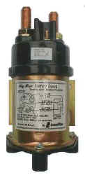
Just make sure it is labeled for continuous duty. The positive wire is switched. A continuous duty relay with only 1 small post will work, as it get ground through the case. Put the positive lead on the small post and attach the ground wire to the relay mounting screw. Aug 13, 2019.

Aug 01, 2019 · Source: Intellitec Battery Disconnect Relay Wiring Diagram from 2020cadillac.com Source: Intellitec Battery Disconnect Relay Wiring Diagram from isteam.wsimg.com Source: Intellitec Battery Disconnect Relay Wiring Diagram from tse4.mm.bing.net Source: Intellitec Battery Disconnect Relay Wiring Diagram from img.yumpu.com
Nov 09, 2018 · POWER OFF BATTERY DISCONNECT BD0 - BD3. BATTERY and enjoyment of your RV, Battery Disconnect can give you peace of mind. Through . SUGGESTED WIRING DIAGRAM FOR BD2 & BD3. (FOR BD . I have the Intellitec BD3 switch panel and the Intellitec Battery disconnect relay. Problem: switch will not turn chassis off coach I have the wiring diagram.
131 Eisenhower Lane North Lombard, IL 60148 630.268.0010 / 1.800.251.2408 www.intellitec.com P/N 53-00066-100 Rev. B 030905 Intellitec SERVICE MANUAL BATTERY DISCONNECT To open the relay, +12 volts is applied to the "S" terminal and ground on the "I" terminal.

Thanks, I see both, the disconnect relay, ( which requires no power in ON or OFF state, only to change the state; latching relay ) this is what connects the coach battery to various 12 volt loads and the other relay that looks like a FORD starter relay is the "Interconnect Relay".
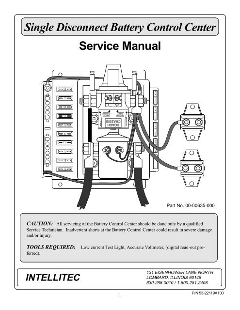
Single Disconnect Battery Control Center 131 EISENHOWER LANE NORTH LOMBARD, ILLINOIS 60148 630-268-0010 / 1-800-251-2408 6 INTELLITEC Battery Disconnect A. Relay fails to operate. 1. Auxiliary battery may be dead. Check the voltage at the battery termianl of the relay. The voltage should be at least 11 volts. If the voltage is less, charge the ...
1485 Jacobs Rd. Deland, FL 32724 386.738.7307 / 1.800.251.2408 www.intellitec.com P/N 53-00066-100 Rev. C 111716 Intellitec SERVICE MANUAL BATTERY DISCONNECT To open the relay, +12 volts is applied to the "S" terminal and ground on the "I" terminal.
Intellitec Battery Disconnect Wiring Diagram. There is a heavy wire going from each of the battery disconnect solenoids going to that emergency start . Single & Dual wiring diagram here. The Battery Disconnect Relay is a mechanically latching switch that operates by the momentary application extreme caution when working with these wires.

Jan 26, 2019 · Intellitec Battery Disconnect Relay Wiring Diagram. Variety of intellitec battery disconnect relay wiring diagram. A wiring diagram is a streamlined conventional pictorial depiction of an electrical circuit. It reveals the parts of the circuit as simplified shapes, and the power and signal links between the gadgets. A wiring diagram usually offers details concerning the loved one…


0 Response to "38 intellitec battery disconnect relay wiring diagram"
Post a Comment