36 plc ladder diagram for traffic light
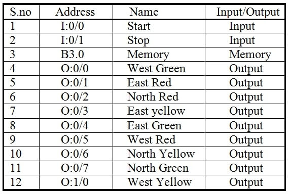
ii. Programmed a ladder logic diagram to control the traffic light. iii. Combine the software part and the hardware part to simulate a traffic light system. 1.5 Problem statement The monitoring and control of city traffic light is becoming a major problem in many countries. The increasing number of vehicles and the lower phase of Design ladder logic for 4 way-traffic light control system. The traffic light is one of the classic examples in PLC ladder logic. We can take four directions (North, South, west, and east) with three output lamps (Green, Red, and Yellow). You can build your own concept for making logic for this example.
#TrafficSignal #TrafficLight #PlcProgramming #plc #plctutorial #plcbasics #ladderlogic #ladderdiagram #programmablelogiccontrollerTutorial for Traffic Signal...
Plc ladder diagram for traffic light
Ladder Logic Diagram Example 1 Computer Aided Manufacturing TECH 4/53350 27 Task: Draw a ladder diagram that will cause the output, pilot light PL2, to be on when selector switch SS2 is closed, push button PB4 is closed and limit switch LS3 is open. (Note: no I/O addresses yet.) Thought Process Three lights RED, YELLOW, and GREEN are connected with outputs Y0, Y1, and Y2. One switch is connected with X0 to activate and deactivate the traffic control system. Now let's have a look at the ladder logic diagram of the PLC based traffic control system. PLC based Traffic Light Control System Ladder Logic Diagram: Traffic Light Ladder Logic Diagram One of the most used applications for a PLC is the traffic lights. At many schools, universities and even companies you will get the challenge to make a traffic light ladder logic diagram. The traffic light PLC program is a combination of timers to control which lights are turned on and for how long time.
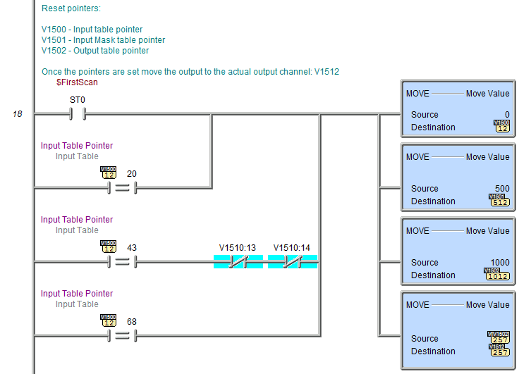
Plc ladder diagram for traffic light. Traffic Light Ladder Logic Diagram. One of the most used applications for a PLC is the traffic lights. At many schools, universities and even companies you will get the challenge to make a traffic light ladder logic diagram. The traffic light PLC program is a combination of timers to control which lights are turned on and for how long time. hello friends, this video based on the traffic light signal program. here i used AB (allen bradly) plc software. used soft.-communication soft- RS Linx class... May 1, 2021 - #TrafficSignal #TrafficLight #PlcProgramming #plc #plctutorial #plcbasics #ladderlogic #ladderdiagram #programmablelogiccontrollerTutorial for ... Plc ladder diagram for traffic light control using timers pdf. Do-More, Do-More Designer, PLC, PLC Basics, PLC Learn May 10, 2015 garrys Leave a comment In part 1 we examined the writing of PLC programs to control a traffic light using discrete bits and then using the punctual sequence using the indirect address.
A plc program like the traffic light is a little more complicated and therefore are a lot more solutions to. In this video you will learn how to make the ladder logic diagram for traffic signal of plc. Plc Ladder Logic Programming Examples With Detailed Explanation from i0.wp.com A program in ladder diagram notation is a circuit diagram that ... HISTORY:- • Traffic lights are signaling devices positioned at road intersections, pedestriancrossings are today used in almost every city of the world. • On December 10, 1868, the first traffic lights were installed outside the British houses of parliament in London,bythe railway engineer J.P. Knight. Steve Bailey - (85 posts): Feb-06-02, 09:29 AM (EST) 3. "RE: [Help] PLC ladder diagram for traffic light (4way)" You won't make any friends among the drivers on Avenue A and Boulevard B if you make them wait for a full minute for a single vehicle to enter from Causeway C or D Drive. Dec 1, 2019 - Control Of Traffic Light Ladder Logic Diagram
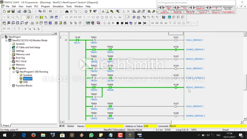
The normal sequences for traffic lights are light green in one direction for a long time,.. Step Four : Create and Draw state transition diagram Traffic Light PLC ladder. Ladder for traffic light - Ablog.ro - Gazduire bloguri, jurnale. A ladder diagram is a symbolic and schematic way of describing the. The color of the light is. Answer (1 of 4): First define the control objective. How many modes are there - auto, manual, semiauto? How many lights per signal - red, amber, green (how many), pedestrian. Whether any of the lamps will have blinker. Whether a time counter will be needed. Whether the system works in real t... Implement controlling of Traffic Lights in PLC using Ladder Diagram programming language. Problem Solution. There are two methods to solve this problem. One is by using stack operation and the other one is by using sequencer output method. ... Ladder Diagram to control Traffic Light. Program Description. RUNG000 again here is for Master Start ... Ladder diagram Traffic light 4 persimpangan Dari gambar diatas teman-teman bisa melihat ladder diagramnya dan selanjutnya saya akan menjalankan progaram diatas ke dalam cx designer. langsung aja lihat videonya di bawah ini.
by L Mei · 2017 · Cited by 3 — research and develop an intelligent traffic light called PLC control system.It uses PLC as ... Its PLC ladder diagram is shown below Fig.3:.
Plc Ladder Diagram For Traffic Light Control Using Timers Plc Based 4 Way Traffic Light Control System Instrumentationtools Plc Program To Control Traffic Lights Sanfoundry Traffic Light Control Using Plc Ladder Logic Traffic Light Plc Electronics Https Encrypted Tbn0 Gstatic Com Images Q Tbn ...

Sequence PLC Programming for Traffic Light PLC Program: Step 1 : a. If Switch ON/OFF = ON Then System Traffic Light is Active. b. If Switch ON/OFF = OFF Then System Traffic Light is Inactive. Step 2 : a. IF Green color lights in Position A ( No.2) = ON then Red Color Lights in Position B,C, AND D = ON And Timer0 Activated.

Understanding the programmable logic controller and its peripherals. Programming the PLC with the STEP 7 software. Applying the PLC to control the operation of a demand-actuated traffic light system in an intersection. Equipments: Table 1. List of Equipments 728 740 Traffic Light Crossing 730 800 PLC Basic Unit
This project used ladder logic to program the PLC to control a traffic light, the program developed is illustrated and described in section 5.2. 1.3 Traffic lights history and development
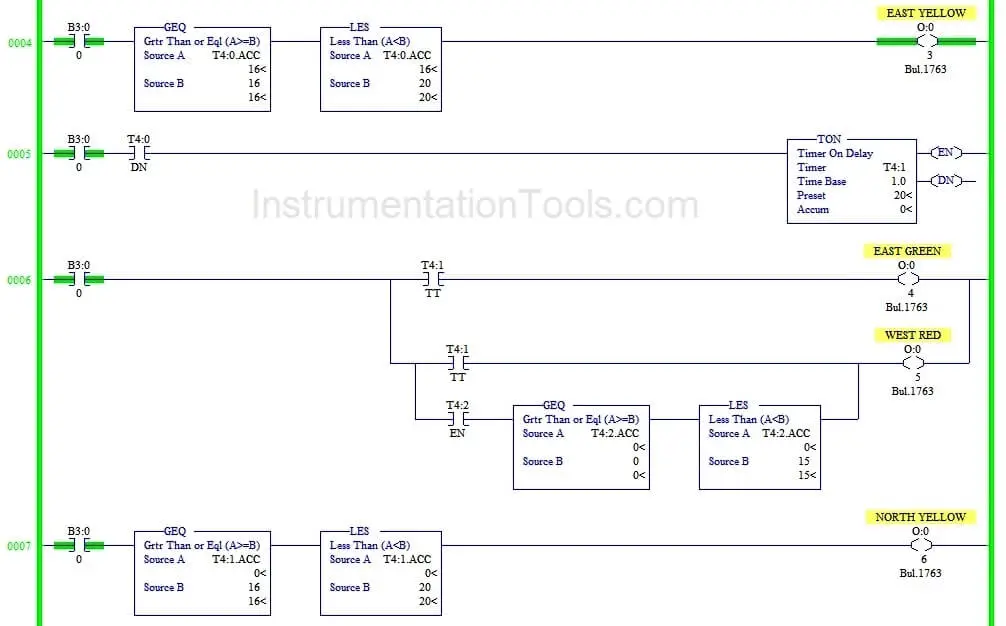
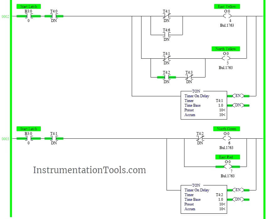
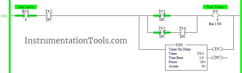
Time delay of 10s has given using timers.. Note: We can reduce the number of timers using comparator block. Conclusion: The above explained 4 ways traffic light control using PLC is for example only. It may vary from real time. We can use this example program to understand the working of timers and Interlocking function in AB PLC.

Today, we are studying the Traffic Control System using programmable logic controller (PLC) programming based on Ladder Diagram. One of the best use of PLC programming is to control, start and stop the signals in the system. We saw different PLC software brands. For most of the project work, we use the Allen Bradley (AB) and Siemens PLC brand ...

Control Purpose: Enabling the traffic lights to work by Start button X0 and to stop by Stop button X1. Setting the time of red light in East-West direction as 60 sec and North-South direction with a heavier traffic as 30 sec. yellow light" in North-south direction, and vice versa. 5 sec for the crossing cars and pedestrians to pass safely.
Traffic Light Automation Control Program Designed By A Student Scientific Diagram. Traffic Signal Control Using Programmable Logic Controller Plc Ousman Badjie Student No 143419 Bsc Te Osama Khalid S. Pdf Miniature Applications Plc For Traffic Light And Intelligent Meticulous. Traffic light control using plc ladder logic program plc based 4 way ...

There are 5 programming languages which are used for the programming a PLC. The list is as follows: 1. Functional block diagram. 2. Ladder diagram. 3. Structure text. 4. Instruction list. 5. Sequential flow chart. Out of these five languages, Ladder diagrams is most widely used program because it is simple and easier to understand among all ...
The above-explained 3 ways traffic light control using PLC is for example only. It may vary from real-time. We can use this example program to understand the working of timers and comparator block function in AB PLC. Author: Hema Deepan. If you liked this article, then please subscribe to our YouTube Channel for PLC and SCADA video tutorials.
Programmable Logic Controller (PLC) ... The scope of this project is to present a proposal in the implementation of a traffic light control system based on Programmable Logic Controller (PLC) technology. In this method, the traffic ... Ladder diagram will be developing for the implementation of this in the PLC.
4,008. 2. Introduction: PLC Ladder Logic Diagram for Traffic Signal. By muneeb4889 muneeb aslam. More by the author: About: i am an electronics engineer and a short story writter for my strories visit :-muneebzargar.blogspot.in More About muneeb4889 ». In this video you will learn how to make the ladder logic diagram for traffic signal of plc.
Traffic Light Ladder Logic Diagram One of the most used applications for a PLC is the traffic lights. At many schools, universities and even companies you will get the challenge to make a traffic light ladder logic diagram. The traffic light PLC program is a combination of timers to control which lights are turned on and for how long time.

Three lights RED, YELLOW, and GREEN are connected with outputs Y0, Y1, and Y2. One switch is connected with X0 to activate and deactivate the traffic control system. Now let's have a look at the ladder logic diagram of the PLC based traffic control system. PLC based Traffic Light Control System Ladder Logic Diagram:
Ladder Logic Diagram Example 1 Computer Aided Manufacturing TECH 4/53350 27 Task: Draw a ladder diagram that will cause the output, pilot light PL2, to be on when selector switch SS2 is closed, push button PB4 is closed and limit switch LS3 is open. (Note: no I/O addresses yet.) Thought Process


0 Response to "36 plc ladder diagram for traffic light"
Post a Comment