35 lighting control panel wiring diagram
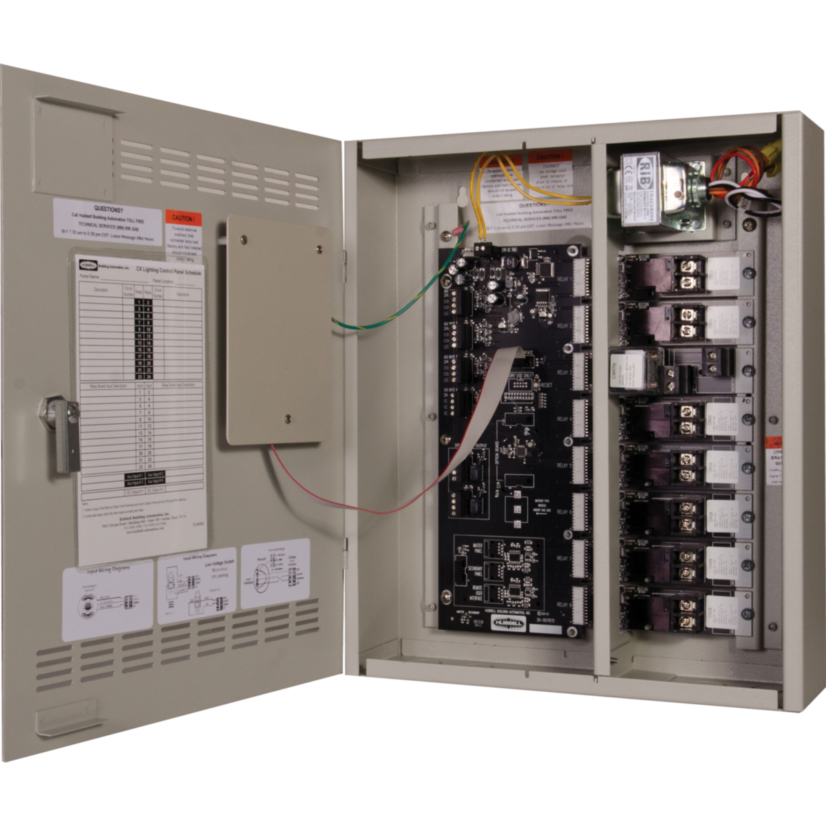
Lighting Control Panel 16 and 24 INSTALLATION INSTRUCTIONS PANEL NOTES • CX Panels are manufactured fully populated with relays or empty without relays. Relays to be purchased separately and to be installed in the field by a certified electrician. • Relays are mounted with lighting circuit terminals in the high voltage area.
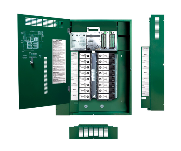
Relay Control Panels Smart Lighting Control. GreenMAX 2 BenefitS of GreenMAX ... Lighting Wire Way 2-Pole Relay Manual Actuator Lower Ventilation Cover Grounding Points Left Panel Cover Door with Split Hinges Lock Wiring Diagram Relay Insert Panel Right Panel Cover Communication Link (Between Command Module and Relay Insert Panel) Command Module.
Assortment of crestron lighting control wiring diagram. A wiring diagram is a streamlined standard photographic depiction of an electric circuit. It shows the parts of the circuit as simplified shapes, and also the power as well as signal connections between the tools.

Lighting control panel wiring diagram
Integrated Lighting System Load Wiring Diagram (Section A) Control Wiring (Section B) Use Crestron certified wire such as CRESNET-NP or CRESNET-P. To ensure optimum performance over the full range of the installation topology, use Crestron certified wire. Failure to do so may incur additional charges if
A wiring diagram is a streamlined standard photographic depiction of an electric circuit. Introduction To Lighting Circuits. Image result for 3 phase wiring diagram, australia Pcell 2wi - 2-wire global photosensor. Lighting control panel wiring diagram. It houses the lighting controller, lighting management software and various types of lighting interface modules. Amr, a Electrician from …
Lighting control panel wiring diagram pdf. Lighting Control Panel 16 and 24 INSTALLATION INSTRUCTIONS PANEL NOTES CX Panels are manufactured fully populated with relays or empty without relays. However a network connection to the Area Controller is required for programming the panel. Relays are mounted with lighting.
Lighting control panel wiring diagram.
Compare Now. HDR Relay, Heavy Duty, 1 pole. HDR-11 | Wattstopper. The HDR-11 is used for control of lighting circuits and other electrical loads in Wattstopper's Peanut Panels, Lighting Integrator Control Panels and Lighting Management Control Panels. See less.
Control zoning is an important aspect of lighting control system design, as zoning is the mechanism through which lighting controls are assigned to lighting loads. A control zone is defined as one or more light sources controlled simultaneously by a single control output.
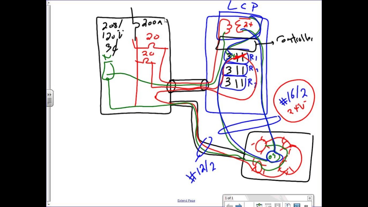
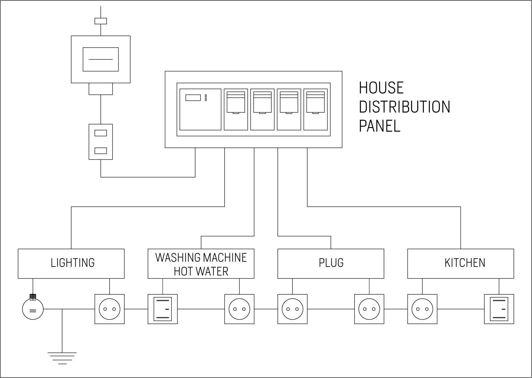
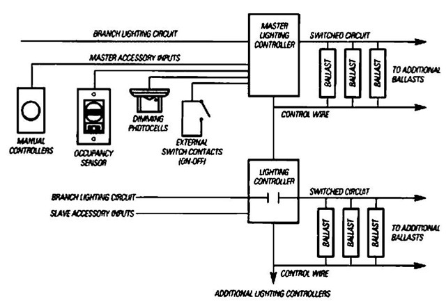
Figure 1). Panelized lighting utilizes a centralized/star wiring configuration, where circuits from the breaker box are routed first to a centrally-located enclosure (panel), which houses dimmer, relay, and other system control modules. From there, the switched/dimmed circuits are routed directly to the loads (see Figure 2).
Lighting Circuits Connections For Interior Electrical Installations 2. Lighting control schematic infrared based system street s physical model emergency with dimming 0 10 v dimmer wiring diagram smart energy efficient of automatic afcs panel lk o circuits connections for led light work the dali intelligent john riley group crestron residential design guide and branch circuit loads hyundai ...
Lighting Control Schneider Electric USA 320 Tech Park Drive, Suite 100 La Vergne, TN, 37086 1-888-778-2733 www.schneider-electric.us Document Number 1200CT0701R11/12 April 2013
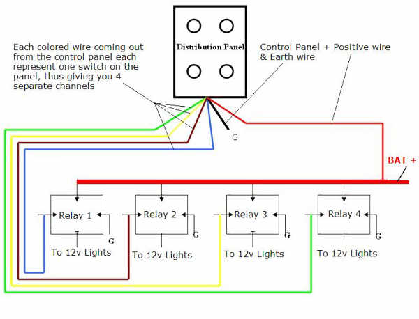
Introduction To Lighting Circuits. Electrical lines which include lighting circuits begin from the main distribution panel of the installation and each line contains three conductors: phase, neutral and ground.All three conductors reach to the terminal point of each luminaire and if it has a metal chassis the ground should be connected in the appropriate position.
Lighting Control Panel. K4 - Installation Guide 38371- C Eng.doc . Page 2 of 22. DOCUMENT'S HISTORY . Review Date Description Authors Release July 2009 Installation Guide writing Marcel Landry A September 2009 General Revision DCI-116 Marcel Landry B October 2012 Page number correction Natasha Brousseau C April 2012 Adapted to the KC600/remove all
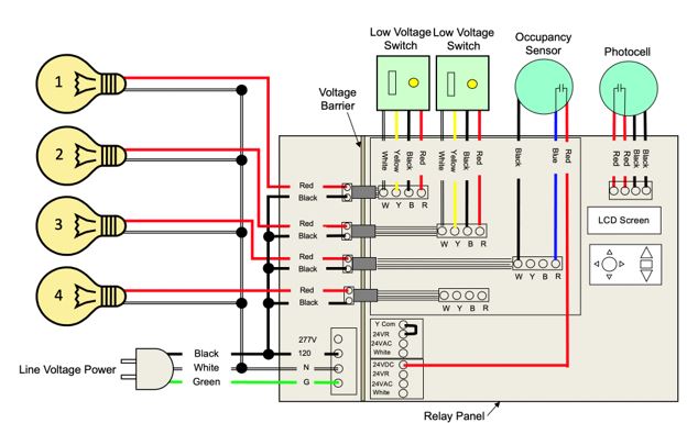
Wiring The Lighting Control panel is made of stainless steel, and has knockouts on the top and bottom of the panel. Control Power 120V AC control power must be supplied to terminal H1 and a neutral to N1 from a maximum 20A breaker. Main Lighting Power The panel can contain contactors and/or terminals to control external contactors.
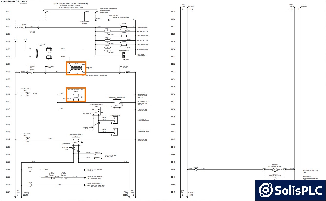
Let's go back and have a look at the control panel, and try and figure out some of the connections by following a wiring diagram. As I've mentioned in the previous articles, this is a control panel that is used for a system that turns wastewater into clean water.. It is a 2-door control panel on the front of which we have some switches that are connected to the PLC inputs and outputs.
PowerHUBB™ PoE Lighting & Control - Low Voltage Switches Installation Sheet. OMNI Ceiling Mount Vacancy/Occupancy Sensor Product Line - OMNI Install Instructions. OMNI Ceiling Mount Vacancy/Occupancy Sensor Product Line - BP1277 Installation Instructions. outlet box, universal power supply and switching relay.
Fifth Light. What is the phone number for Cooper Controls ? What is a DAC ; What is Fifth Light LMS? Does the Fifthlight central server back up the LCP panels progamming? Can a 1-button DALI wallstation be reconfigured into a 2-button control later on? Is the wiring for 1-button/2-button the same?
The NX™ Lighting Control Panel is designed to operate as part of a NX Networked Lighting Control system. Once programmed, the panel will operate independently from a network connection. No software installation is required. However, a network connection to the Area Controller is required for programming the panel.
Control panel circuit diagram | electrical circuit diagram ...
For approved wire types per control method, refer to "Appendix A: Standard Wiring" on page 22. Each Lighting Control Panel contains a Controller PCB for connection of control wiring. The Controller PCB also contains jumpers for termination of DMX512 signal and connection to Auxiliary panels. To connect control wiring: Step 1.
Control of lighting and branch circuit loads | tes engineering
Consult Wiring Diagram A. nLight Control System Installation Worksheet/nLight Project Installation Form/ . in a room or area that are daisy-chained wired together with CAT-5 cabling. A New Dawn in Lighting Controls. The nLight® solution is a digital networked lighting control system that provides both energy savings and increased user ...
Cx lighting control panels 4, 8, 16 and 24 relays | hubbell ...
and productive workspace, requires an intelligent lighting control system. Providing light, where and when needed, while reducing lighting in unoccupied areas is the main function of an intelligent lighting control system. The Solution—POWERLINK G3 For many designers, the task of engineering a suitable lighting control system

Lighting control panel – sra international
Voltage Rating. (37) nLight AIR Wireless. (42) nLight Wired. (1) Sensor Switch JOT Wireless. Compliance. (41) 2700 K. (41) 3000 K. (41) 3500 K. (41) 4000 K.
Lighting control panel
Lighting Control Relay Panel Wiring Diagram. Lighting control schematic lk o cx commercial panels 4 and 8 relay emergency with dimming functional devices inc panel retrofit available for the ilc intelligent controls lightmaster goknight low voltage electrical wiring systems inspection repair guide 0 10 v dimmer diagram system png 1140x937px 010 ...
Lighting circuits connections for interior electrical ...
• Bypass jumpers included for load mis-wire protection • Panels are available in two sizes: 1613 mm (63.5 in) and 921 mm (36.3 in) tall ... panel Pre-Assembled Lighting Control Panel for HomeWorks ... System Diagram
Lighting control panel 11 05 13
Wiring Diagrams. Search the Lutron archive of wiring diagrams. To find a diagram for a specific product or system, please use the drop-down menus below. For more information, please submit a request for product literature, or contact a Customer service representative. You can also call us at +44 (0)207.702.0657.
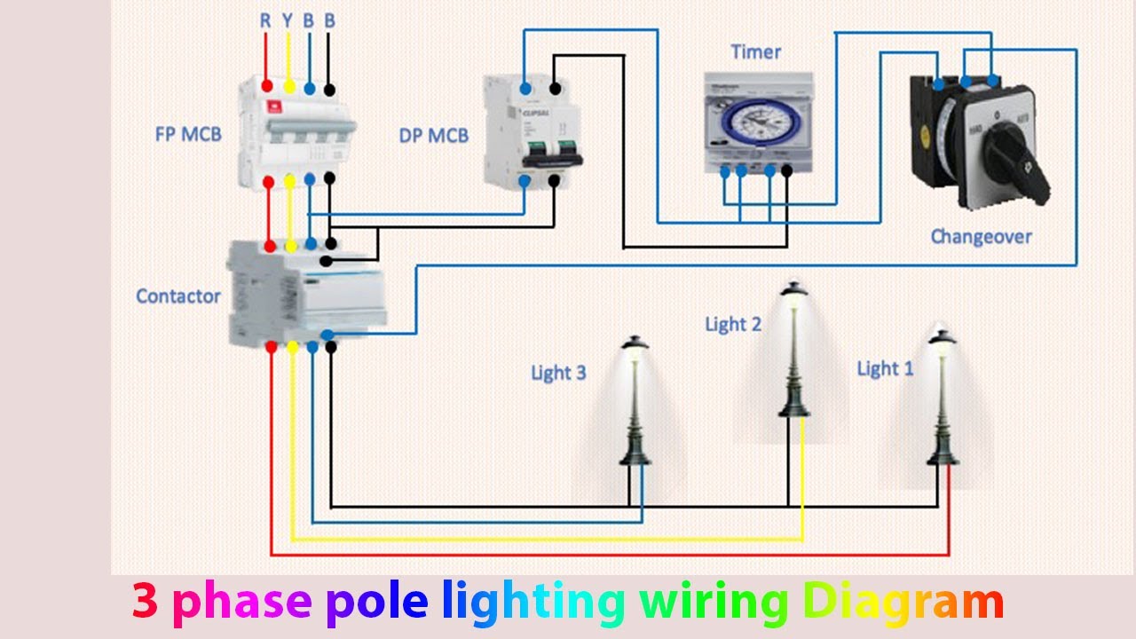
3 phase pole lighting wiring diagram | light manual | light automatic
Wiring Diagrams : LSDMXD, LSDMXD-R : pdf R20D Relay and LVS EPC-2 (WD1003) Wiring Diagrams : R20D, EPC-2 : pdf Apprentice 3 Panel (WD0003) Wiring Diagrams : AP3-4, AP3-8, AP3-16, AP3-24, AP3-32 : pdf Wet Location Touch Switch Input Module (WD0401) Wiring Diagrams
Crestron residential lighting design guide
9 Control Wiring ... standards now require automatic lighting control strategies in virtually every lighting application, including exterior and parking structure general lighting. These strategies, ... Panel-based dimming is available. Dimming is limited to 50% of lamp power.
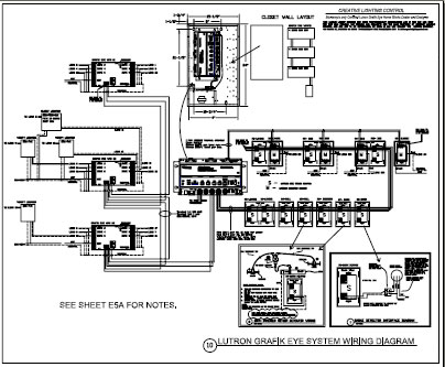
Creative lighting control
Lighting Control & Design recommends the use of pre-made and pre-tested Ethernet style cables. These can even be pulled through conduit with little difficulty. In most cases the cabling does not have to be in conduit though plenum rated cable may be required. The Wiring diagram shown is from www.lanshack.com.

Lighting control system of schneider knx actuator dimming module wiring/programming hindi+eng sub/cc
Customize the user experience in your facility's lighting control system. A Lighting Solution for American Airlines Arena. American Airlines Arena, home of the Miami Heat professional men's basketball team, found it was like many arenas across the nation - fitted with unsupported, outdated Musco Lighting's Microlite lighting control panels.
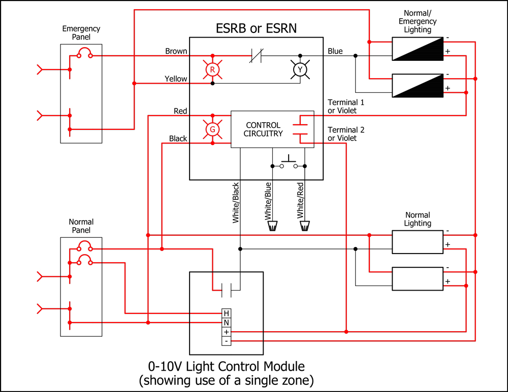
Emergency lighting with dimming control - functional devices ...
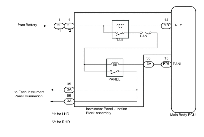
Instrument panel illumination circuit
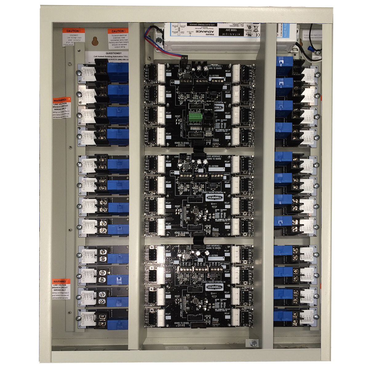
Cx lighting control panels 4, 8, 16 and 24 relays | hubbell ...
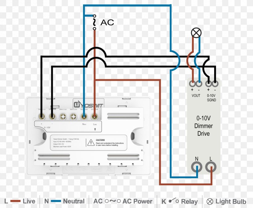
0-10 v lighting control dimmer wiring diagram lighting ...

Diesel generator control panel wiring diagram | electrical ...
Lighting circuits connections for interior electrical ...
Control4® panelized lighting: reference guide for electricians

Lighting control schematic. | download scientific diagram
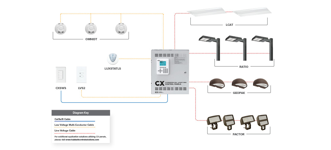
Cx commercial lighting control panels system | hubbell ...
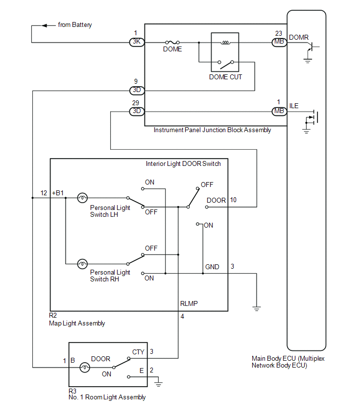
Toyota ch-r service manual - interior light circuit ...
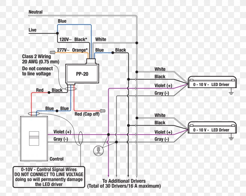
0-10 v lighting control wiring diagram dimmer circuit diagram ...
Lighting circuits connections for interior electrical ...
Single-line diagram how to represent the electrical ...
How to install control panel

Afcs control panel wiring diagram
Electrical panel wiring diagram
Steve mesh talks benefits for electrical contractors to learn ...
Lighting controls (energy engineering)
Crestron residential lighting design guide

File:wiring diagram of lighting control panel for dummies.jpg ...

Diesel generator control panel wiring diagram ac connections ...

Lighting control panel 10 30 12
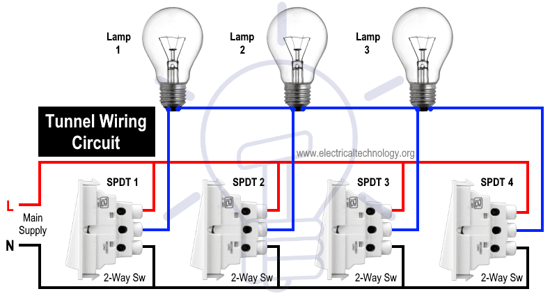
Tunnel wiring circuit diagram for light control using switches
0 Response to "35 lighting control panel wiring diagram"
Post a Comment