40 what is a ray diagram
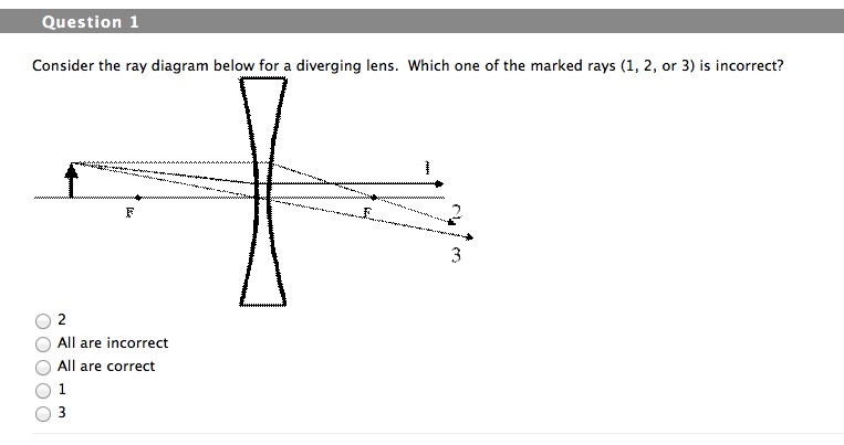
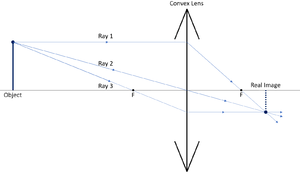
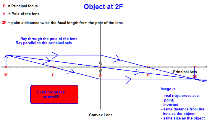
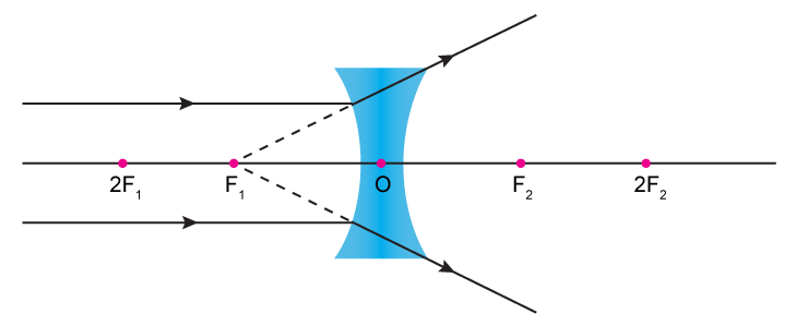
Figure 2.4 represents a spot diagram. It can be seen how this diagram is generated by considering the ray locations on the image plane (a-e) in figure 1. If these ray locations are rotated about the optical axis, the image would result in a center spot with concentric rings surrounding it, which is just what we have in figure 2.4. Ray Diagrams for Lenses. The image formed by a single lens can be located and sized with three principal rays. Examples are given for converging and diverging lenses and for the cases where the object is inside and outside the principal focal length.
This physics video tutorial on optics provides a basic introduction into ray diagrams. It explains how to draw ray diagrams for converging lens, diverging l...
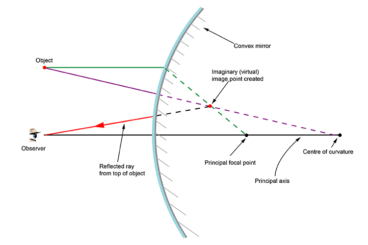
What is a ray diagram
This video covers:- How to draw ray diagrams for convex and concave lenses - How to comment on whether an image is real or virtual, upright or inverted, and ... Ray Diagrams. Jonathan is a published author and recently completed a book on physics and applied mathematics. All lenses and mirrors can use ray diagrams to find images. There are three principal rays. The first principal ray occurs when the light comes in parallel to the principle axis, it goes out through the focus. Draw ray diagrams to show the image formation of an object by: (i) Hypermetropic eye (ii) Correction made with a suitable lens for the hypermetropic eye. Science | Lakhmir Biology (2020, 2021) All. Q2. Draw three labelled ray-diagrams to show the defect of vision called hypermetropia and how it is corrected by using a lens. Also name the lens used.
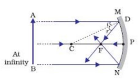
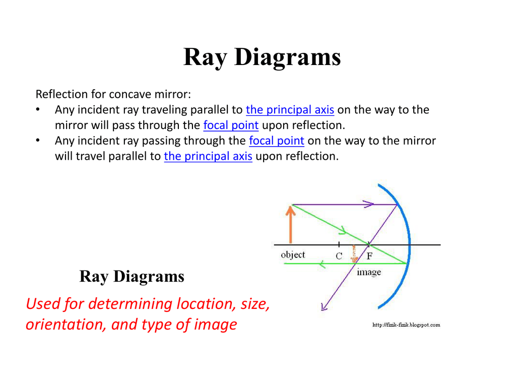
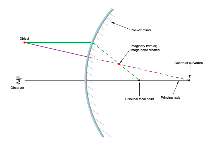
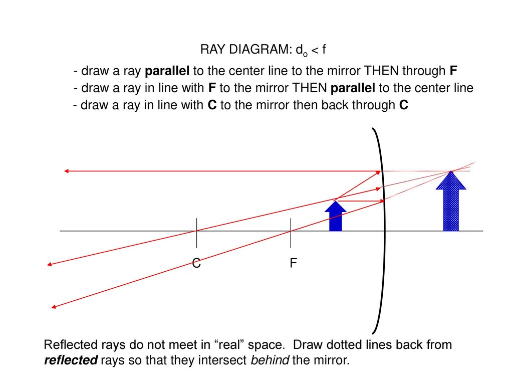
What is a ray diagram. Ray Diagrams for Lenses. Three principal rays can be used to locate and size the image formed by a single lens, with examples for converging and diverging lenses. The three principal rays are:. A ray from the top of the object proceeding parallel to the centerline perpendicular to the lens, passing through the principal focal point beyond the lens. A cathode-ray tube is a device that uses a beam of electrons in order to produce an image on a screen. Cathode-ray tubes, also known commonly as CRTs, are widely used in a number of electrical devices such as computer screens, television sets, radar screens, and oscilloscopes used for scientific and medical purposes. Ray diagrams help us trace the path of the light for the person to view a point on the image of an object. Ray diagram uses lines with arrows to represent the incident ray and the reflected ray. It also helps us trace the direction in which the light travels. Plane Mirror vs Spherical Mirrors. Rule 2 - Ray passing through focus will become parallel to principal axis after reflection. For a concave mirror , we see that ray passing through focus becomes parallel to principal axis after reflection. For a convex mirror, since focus is on the right side, it appears that ray passes through focus, and then it becomes parallel to principal axis.
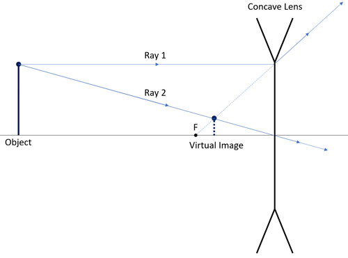
In a ray diagram, a convex lens is drawn as a vertical line with arrows pointing outwards in both directions. This is to resemble the shape of a convex lens. Whereas a concave lens is drawn as a vertical line with arrows pointing inwards. This is to resemble the shape of a concave lens. You can see this below: The students can use a convex lens ray diagram to study the changes in the path of the rays. They can create the image by hand, but the process is challenging, and the students may fail to create a high-quality diagram. 2.1 How to Create Convex Lens Ray Diagram from Sketch They can follow these steps to make a convex lens ray diagram: Jun 27, 2014 · A ray diagram is a diagram used to trace the path that light takes in order for a person to view a point on the image an object. Ray diagrams are commonly constructed to follow light rays through ... Ray Diagram for Object Located at the Focal Point Thus far we have seen via ray diagrams that a real image is produced when an object is located more than one focal length from a converging lens; and a virtual image is formed when an object is located less than one focal length from a converging lens (i.e., in front of F ).
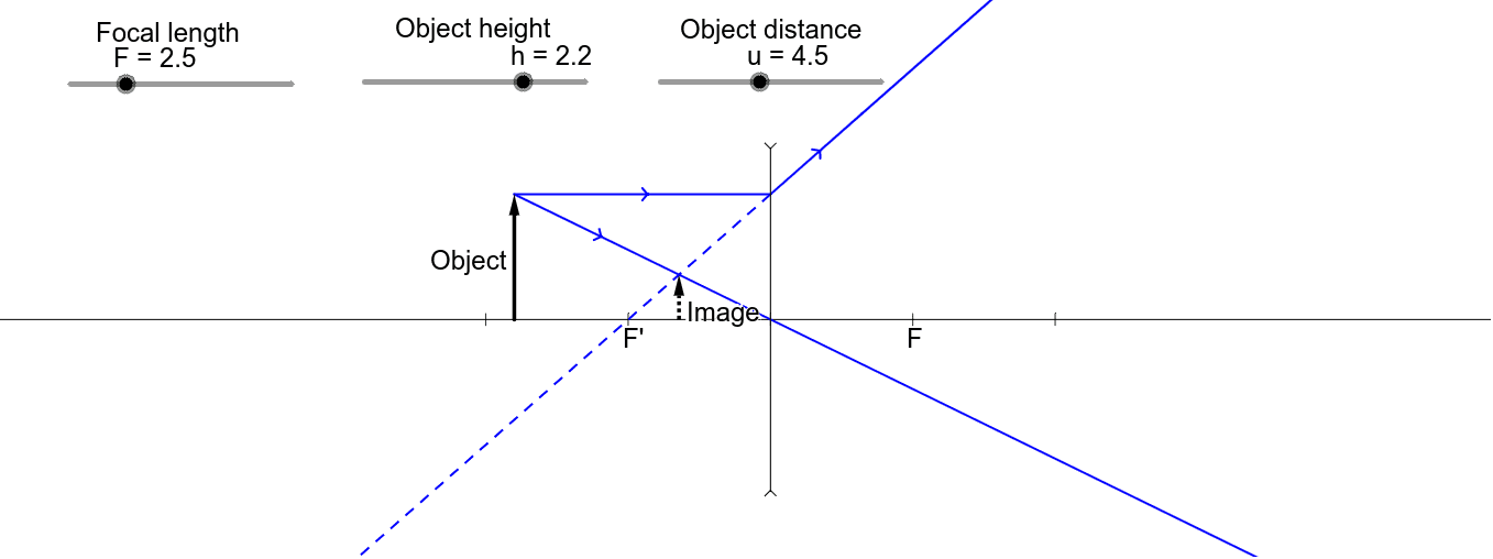
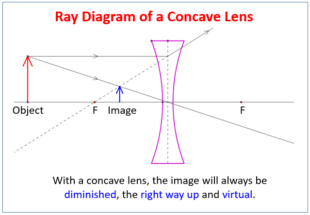
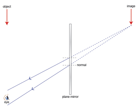
Rule 3 - Ray passing through Optical Center will emerge without deviation. For a both convex and concave lens, we see that ray passing through Optical center emerges without deviation. Next: Convex Lens - Ray diagram→. Facebook Whatsapp. In this diagram : "Ray 1" is traced backwards after being refracted by the lens . "Ray 2" is shown passing through the centre of the lens. This ray is also traced backwards. The diagram shows that a diminished virtual image is produced at the point that the 'traced' lines from "ray 1" and "ray 2" cross one another. This section of Lesson 2 details and illustrates the procedure for drawing ray diagrams. Let's begin with the task of drawing a ray diagram to show how Suzie will be able to see the image of the green object arrowin the diagram below. For simplicity sake, we will suppose that Suzie is viewing the image with her left eye closed. Thus, we will focus on how light travels from the two extremities of the object arrow (the left and right side) to the mirror and finally to Suzie's right eye as she sights at the image. The four steps of the process for drawing a ray diagram are listed, described and illustrated below. 1. Draw the image of the object. 2. Pick one extreme on the image of the object and draw the reflected ray that will travel to the eye as it sights at this point. 3. Draw the incident ray for light traveling from the corresponding extreme on the object to the mirror. 4. Repeat steps 2 and 3 for all other extremities on the object. Figure 2: Block Diagram of X-Ray Operation/Working of X-Ray Machine High voltage source and high voltage transformer. High voltage source is responsible for providing high voltage to the H.V transformer for a decided time. The H.V transformer produces 20 KV to 200 KV at the O/P. These voltages are used to determine the contrast of the image.
Video transcript. Identify all the rays shown in the image below. and this is a reminder what a ray is. A ray start at some point and then goes on forever in some direction. In order to find a ray you need that point that you're starting off on so let's that point over there is called X and then you need another point that sits on the ray and ...
Ray diagram • A ray diagram is a representation of structural formula. It provides information such as speed in each stage, the transmission ratio in each stage, The total number of speeds and its values. • As seen in fig. (a) the maxi speed and minimum speed both are higher for shaft. This requires smaller size of shafts due to reduced torque.
Answer: Taking two principal rays, the ray diagram below (courtesy of Wikipedia) would be sufficient as an answer. But for emphasis, please consider a third ray emanating from the top of the object (as the other two) and direct it to the POLE of the mirror. The ray would reflect off the mirror fo...
A ray diagram is a representation of the possible paths light can take to get from one place to another. This is often from a source or object to an observer or screen. There are a few important things to note: Light travels in straight lines within a uniform medium (this means that light can change direction upon entering a different medium).

Please Explain With Help Of A Ray Diagram Crack In A Glass Vessel Often Shines Like A Mirror Png Image Transparent Png Free Download On Seekpng
A ray diagram is a representation of structural formula. It provides information such as speed in each stage, the transmission ratio in each stage, The total number of speeds and its values. The following diagram is a ray diagram of a 12 speed gearbox.
Plane mirror- Definition, Properties and Ray Diagram. Mirrors are defined as one side-polished surface that can reflect the light rays. Plane mirrors in physics are the ones that have a flat reflecting surface and produce always a virtual image. In this tutorial, we review the most important topics in the plane (flat) mirrors in physics ...
It is important to be able to draw ray diagrams to show the refraction of a wave at a boundary. To draw a ray diagram: Draw a ray from the object to the lens that is parallel to the principal axis ...
sound-ray diagram References in periodicals archive ? The main principles of electron microscopy can be understood by use of optical ray diagrams (2,3), as shown in Fig.
The interactive diagram provides a focus for the attention of the whole class. Your job here is to talk through each of the steps of constructing the ray diagram, engaging the pupils in discussion as you proceed. First, the pupils explore the formation of images using a pinhole camera with one, three and many pinholes. Talking through the ray ...
Ray diagrams. A ray diagram shows how light travels, including what happens when it reaches a surface. In a ray diagram, you draw each ray as: a straight line;
A grid of points is defined at the entrance or exit pupil. of an optical system and rays are traced from the object point. through the grid points, through the observation plane.
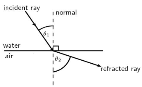
A ray of green light enters a liquid from air, as shown in the figure. The angle 1 is 45 o and angle 2 is 30 o. (a) Find the refractive index of liquid. (b) Show in the diagram the path of the ray after it strikes the mirror and re-enters in air. Mark in the diagram the angles wherever necessary.
Draw ray diagrams to show the image formation of an object by: (i) Hypermetropic eye (ii) Correction made with a suitable lens for the hypermetropic eye. Science | Lakhmir Biology (2020, 2021) All. Q2. Draw three labelled ray-diagrams to show the defect of vision called hypermetropia and how it is corrected by using a lens. Also name the lens used.
Ray Diagrams. Jonathan is a published author and recently completed a book on physics and applied mathematics. All lenses and mirrors can use ray diagrams to find images. There are three principal rays. The first principal ray occurs when the light comes in parallel to the principle axis, it goes out through the focus.
This video covers:- How to draw ray diagrams for convex and concave lenses - How to comment on whether an image is real or virtual, upright or inverted, and ...
A To Construct A Ray Diagram We Use Two Light Rays Which Are So Chosen That It Is Easy To Know Their Directions After Reflection From The Mirror Studyrankersonline
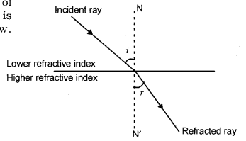
With The Help Of A Ray Diagram State What Is Meant By Refraction Of Light Cbse Class 10 Science Learn Cbse Forum














0 Response to "40 what is a ray diagram"
Post a Comment