40 the technique illustrated in the diagram is known as
Technique as defined in 1992 by the author, and as taught to individuals since 1998 and to teams since 1999. The Context section delineates the problem linked to time, the goals of the Pomodoro Technique and its basic assumptions. Material and Method describes the Pomodoro Technique, and shows how to apply it by reaching incremental objectives. Benefits of The Kivin Method. There are three main benefits of the Kivin method: Access to stimulate the perineum — that's the skin connecting the vagina and anal openings is especially nerve-dense and still frequently overlooked during oral. Second, better access to the entire vulva. While straight-on oral gives the giver direct ...
20 Questions Show answers. In preparation for an electrophoresis procedure, enzymes are added to DNA in order to. The parents of a new baby believe they brought the wrong child home from the hospital. Gel electrophoresis was performed using DNA samples from the parents and the child. A section of the gel.
The technique illustrated in the diagram is known as
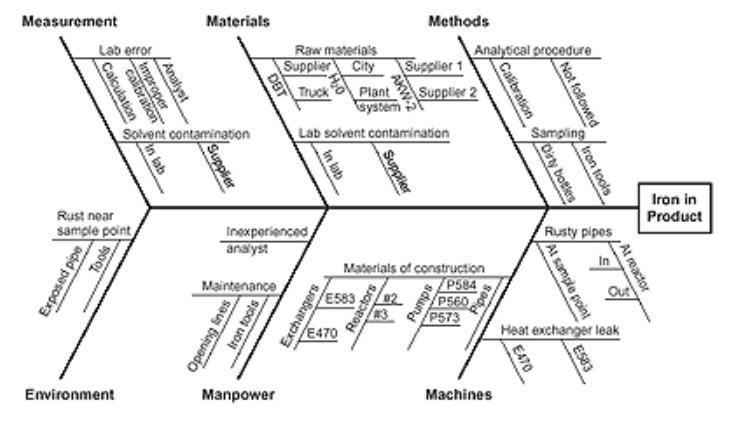
A Cause-and-Effect Diagram is a tool that is useful for identifying and organizing the known or possible causes of quality, or the lack of it. The structure provided by the diagram helps team members think in a very systematic way. Some of the benefits of constructing a Cause-and-Effect Diagram (Viewgraphs 2) are that it! United States. National Bureau of Standards · Weights and measuresA block diagram of the transmitter is presented in figure 2. ... The technique illustrated operates on the anode voltage dynamic pushing characteristic of ... Alison Pitt · 2003 · Study Aids... male gamete 18 The technique illustrated in the diagram is known as (1) cloning (2) genetic engineering (3) protein synthesis (4) in vitro fertilization ...
The technique illustrated in the diagram is known as. 18.The diagram below represents a process that occurs during normal human development. Which statement is correct regarding the cells and DNA? A)carbohydrate B)gene C)ribosome D)chromosome 19.The diagram below shows some of the steps in protein synthesis? The section of DNA being used to make the strand of mRNA is known as a A)recombination B ... The diagram below represents a technique used in some molecular biology laboratories( refer to question 2) which phrase best describes a possible result of this process? The production of a human hormone by the bacterial cell. Female mosquitoes spread diseases when they bite humans to obtain blood. It is only the females that do the biting. Research is being conducted to alter the DNA of male ... Data flow diagram often used in connection with human process and can be displayed as workflow diagram. The critical Process Flow Diagram is another flowchart technique for designing data flow in connection with organizational processes. The critical Process flow diagram may use different range of symbols than a classic workflow diagram. The fishbone diagram, invented by Ishikawa Kaoru, a Japanese chemist, (hence why it is also referred to as the Ishikawa diagram) aims to help companies find solutions to problems and their causes in a structured way.It is therefore also called the cause-effect diagram.Every problem, requiring a sustainable solution, is graphically illustrated with its respective causes in the diagram.
1963 · GeologyThe results in a new scatter diagram . slope of curve 11 is nearer to the ... Plot the vertical deviations from curve 6 of the The technique illustrated has ... S. Balemi, P. Kozák, R. Smedinga · 2012 · ScienceINTRODUCTION The synthesis technique illustrated in this paper was first ... is based on a data structure known as a binary decision diagram (BDD) [2]. NETWORK ANALYSIS Part 1 - AN INTRODUCTORY NOTE Samithamby Senthilnathan PhD (Business), M.Sc (Management), B.Sc (Business Administration) Department of Management, FCM Eastern University, Sri Lanka Abstract The main objective of this paper is to provide an introduction about the Network, particularly in relation to the basic aspects of drawing a network diagram. Diagram & How To Attempt It. Talk together with your associate about in the event that they'd like different areas stimulated. In case your associate is into it, you possibly can slide a finger into both the vaginal opening or the anus whereas utilizing your tongue. "Not everybody likes penetration, or penetration coupled with cunnilingus ...
Structure B represents a) a ribosome b) recombinant DNA c) transfer RNA d) a female gamete e) a rubber band 64. The technique illustrated in the diagram is known as a) cloning b) protein synthesis c) genetic engineering d) in vitro fertilization e) weird sex by this technique known as selective breeding. C)This technique is used by farmers to eliminate mutations in future members of the species. D)Since the development of cloning, this technique is no longer used in agriculture. 7.Which statement provides accurate information about the technique illustrated below? A)cloning of selected body cells the technique illustrated below? 10. ll. 12. ... by this technique known as selective breeding. C) This technique is used by farmers to eliminate ... 27. A laboratory technique is represented in the diagram 26. Some goats have been genetically modified with a human gene that codes for a blood anti-clotting factor. The anti-clotting factor can ... More recently, airports in Europe and Asia have been using a well-known risk assessment model called â bow-tie.â The name is related to the shape of the diagram used in the risk assessment. Atypi- cal bow-tie diagram is illustrated in Figure 17.
The technique for this procedure is known as 1) cloning 2) gene manipulation 3) direct harvesting 4) reproduction Human ... 1 6) What process is illustrated in the diagram below? 2) meiosis 3) direct harvesting 4) chromatography l) enetic engineering Remove insert Spider DNA from the spider Produces
Technique Required? Definition (from Wikipedia) Class and Web Sources Stanford Examples; Context Diagram: Required: A system context diagram (SCD) in software engineering and systems engineering is a diagram that defines the boundary between the system, or part of a system, and its environment, showing the entities that interact with it.This diagram is a high level view of a system.
The technique illustrated in the diagram is known as 1. cloning 3. protein synthesis 2. genetic engineering 4. in vitro fertilization. 2. Structure B represents 1. a ribosome 3. recombinant DNA 2. transfer RNA 4. a male gamete. 3. Which condition would most likely produce a change in the gene pool of a population? 1. a large population 3. migrations out of the population 2. random mating in ...
The 5 Whys can be used individually or as a part of the fishbone (also known as the cause and effect or Ishikawa) diagram. The fishbone diagram helps you explore all potential or real causes that result in a single defect or failure. Once all inputs are established on the fishbone, you can use the 5 Whys technique to drill down to the root causes.
The block diagram of a system is illustrated in the figure shown, where X (s) is the input and Y (s) is the output. The transfer function H ( s) = Y ( s) X ( s) is. This question was previously asked in. GATE EC 2019 Official Paper. Download PDF Attempt Online. View all GATE EC Papers >. H ( s) = s 2 + 1 s 3 + s 2 + s + 1.
Use the diagram below to answer questions 43 and 44 The breeding posture illustrated in the diagram is known as – 2. A. reproductive swimming; B. amplexus
The Pomodoro Technique was created with the aim of using time as a valuable ally to accomplish what we want to do the way we want to do it, and to empower us to continually improve our work or study processes. This paper presents the Pomodoro Technique as defined in 1992 by the author, and as taught to individuals since 1998 and to teams since 1999. The Context section delineates the problem ...
3. The technique illustrated in the diagram is as (1.) cloning (2.) protein synthesis Anima! genetic engineering in vitro fertilization B 4. Explain why this technique is also called Z '5/7. List three practical applications of this to human health and/or agriculture dacterial Cell ceil 8.
Name the type of diagram that shows locations of genes on a chromosome. ... The technique illustrated in the diagram is known as, genetic engineering.
The diagram below represents a scientific techniques in use today. Scientists have used this technique to . Produce hormones for human use at a lower cost than other methods. The diagram below represents a technique used in some molecules biology laboratories. Which phrase best describes a possible result of this process? The production of a human hormone by the bacterial cell. Base your ...
The technique illustrated in the diagram is most likely A. Cloning B. Protein synthesis C. gel electrophoresis D. genetic engineering 6. Design your own! You are a very successful scientist and know everything about making transgenic organisms. You want to invent a new organism that will be useful to society in some way. a.
Geological Survey (U.S.) · 1963 · GeologyThe results in a new scatter diagram . slope of curve 11 is nearer to the ... Plot the vertical deviations from curve 6 of the The technique illustrated has ...

The vibrational states of a string gives rise to the SAKURAI GRAVITON shown captured in full dimension. DSS00320 M1-9
An illustration is a decoration, interpretation or visual explanation of a text, concept or process, designed for integration in print and digital published media, such as posters, flyers, magazines, books, teaching materials, animations, video games and films.An illustration is typically created by an illustrator.Digital illustrations are often used to make websites and apps more user ...
How Honeypot Works – Illustrated With a Diagram. Honeypots are strategically built to hoax the cyber criminal into believing they have found a way to alter rights and steal authorizations. When the trap is triggered, an alarm is sent to a central deception server that takes note of the affected decoy and the attack vectors that were used by the cyber criminal. It is designed deliberately ...
This article is a visualisation of 10 common CNN architectures, hand-picked by yours truly. These illustrations provide a more compact view of the entire model, without having to scroll down a couple of times just to see the softmax layer. Apart from these images, I've also sprinkled some notes on how they 'evolved' over time — from 5 ...
Spaghetti diagram is a method that uses a continuous line to trace the path and distance traveled of a particular object or person throughout a process. It is most commonly illustrated on a floor map diagram that contains the entire process you are evaluating; i.e. a manufacturing floor, hospital floor, office layout, etc.
Q. The separation technique that involves heating a solution until the liquid changes into a gaseous state, leaving behind a solid is known as. answer choices. evaporation. crystallization. centrifuge. chromatography.
The diagram below shows the electronic structure of Na metal : The Auger Process & Auger Spectroscopy Now let us return to the subject of Auger spectroscopy - in the following discussion, the Auger process is illustrated using the K, L1 & L2,3 levels. These could be the inner core levels of an atom in either a molecular or solid-state environment.
7 QC Tools are also known as Seven Basic Quality Tools and Quality Management Tools. These graphical and statistical tools are used to analyze and solve work-related problems effectively. The 7 Quality Tools are widely applied by many industries for product and process improvements, and to solve critical quality problems.. 7QC tools are extensively used in various Problem Solving Techniques ...
23 Apr 2020 — What is the name of the genetic engineering technique illustrated in diagram 2 above. 1. See answer. Add answer+5 pts. Log in to add comment.1 answer · 0 votes: Answer:Genetic engineering may be defined as the deliberate manipulation or alteration of the genetic information of an organism. Among the various forms ...
Alison Pitt · 2003 · Study Aids... male gamete 18 The technique illustrated in the diagram is known as (1) cloning (2) genetic engineering (3) protein synthesis (4) in vitro fertilization ...
United States. National Bureau of Standards · Weights and measuresA block diagram of the transmitter is presented in figure 2. ... The technique illustrated operates on the anode voltage dynamic pushing characteristic of ...
A Cause-and-Effect Diagram is a tool that is useful for identifying and organizing the known or possible causes of quality, or the lack of it. The structure provided by the diagram helps team members think in a very systematic way. Some of the benefits of constructing a Cause-and-Effect Diagram (Viewgraphs 2) are that it!











0 Response to "40 the technique illustrated in the diagram is known as"
Post a Comment