40 part winding start motor wiring diagram
The post start with a wrong winding diagram, this drawing belongs to one two speed one winding motor (dahlander),and post sayd Part Winding, later we have receive a semi-hermetic compressor name plate and exetrnal wiring, both belongs to part winding motor. They are normally delta run motors. The reason manufactures make 12 lead, single voltage motors, are so you can use part winding start, or wye-delta start. So if you're running a soft starter, your connection is right. The easiest way to tell is, if it has only one voltage rating on the name plate. Edit: Your connection, not the motor shops.
Part Winding Start. Home/Information/EASA Electrical Engineering Handbook/Part Winding Start. Part Winding StartJohnGierich2021-04-29T13:44:52-05:00.

Part winding start motor wiring diagram
In this video I cover the basics of an part winding motor starterFor other videos on reduced voltage starting methods:Wye-delta starter: https://youtu.be/kQU... Part winding motor starters démarrage des moteurs asynchrones à bobinage connection electric motors generators engineering eng tips start terminals at the terminal plate reduced voltage starter direct from galco electronics electrician talk ecoline with se b pw designed for utilize only a portion of up this means wind technical information avoid costly mistakes efficient plant star delta ... Part winding starter wiring diagram. This is a post titled part winding start motor wiring diagram we will share many pictures for you that relate to part winding start motor wiring diagram. In this lesson well examine part winding reduced voltage starters. Hopefully the picture gallery below will be useful for you.
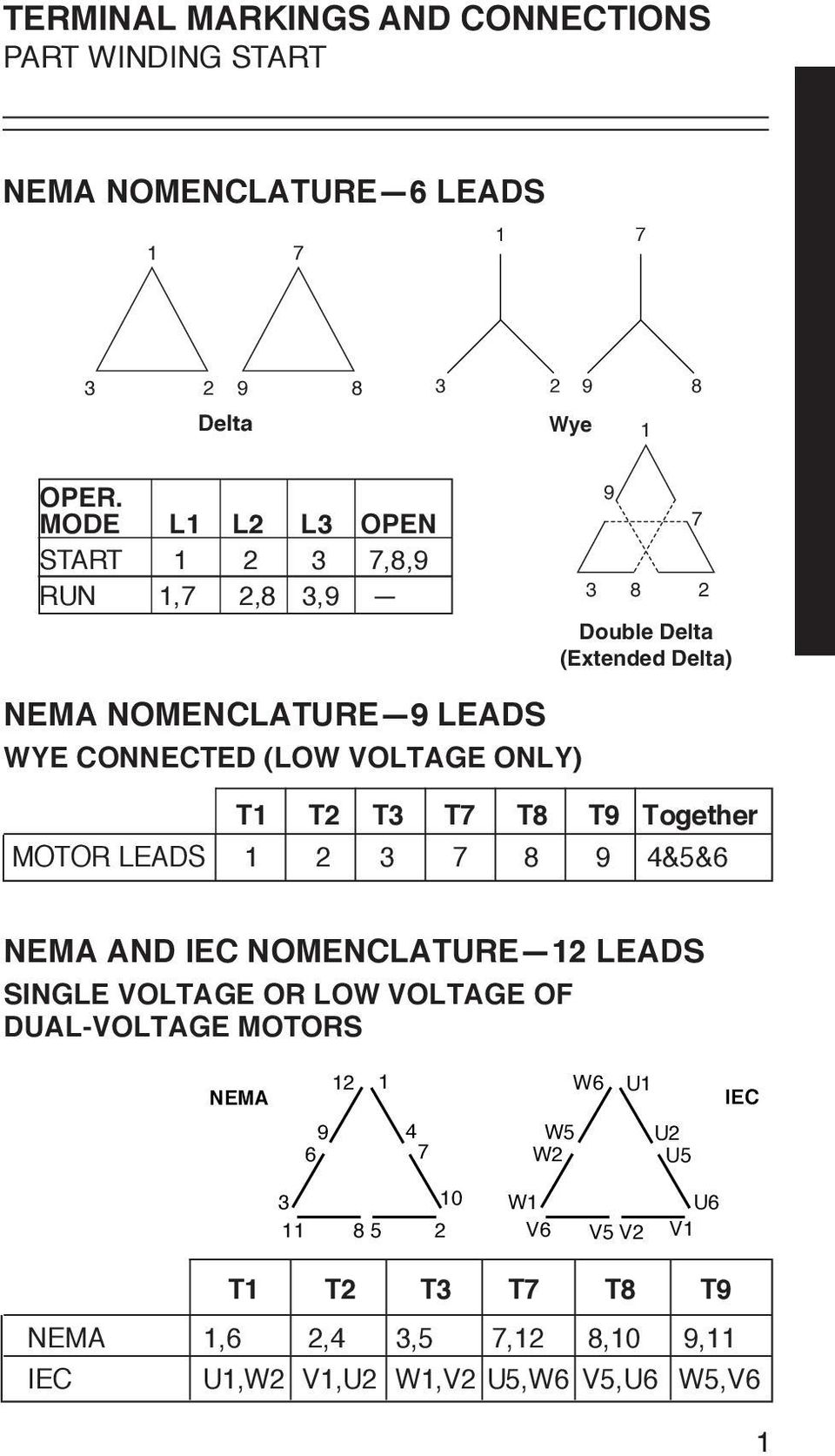
Part winding start motor wiring diagram. motor leads 1237894&5&6 nema and iec nomenclature—12 leads single voltage or low voltage of dual-voltage motors t1 t2 t3 t7 t8 t9 nema 1,6 2,4 3,5 7,12 8,10 9,11 iec u1,w2 v1,u2 w1,v2 u5,w6 v5,u6 w5,v6 terminal markings and connections part winding start 12 9 6 3 11 8 5 2 10 1 7 4 w6 w5 w2 w1 v6 v5 v2 v1 u6 u1 u5 u2 nema iec nema nomenclature ... 1-Blue 5-Black P1-No color assigned. 2-White 6-No color assigned P2-Brown. 3-Orange 7-No color assigned. 4-Yellow 8-Red. Three Phase Connections: Part Winding Start: 6 Leads NEMA Nomenclature: WYE or Delta Connected. T1. 4/5/2018 Part Winding Start: How It Works and Advantages ... Motors that divide the winding in half will se e a 50% reduction in current at start-up. Motors that split the winding two thirds to one third energizing two thirds will see a current reduction of 33% at start-up. A couple of advantages of using part windi ng start is to minimize ... A motor designed to operate at a single voltage requires only three leads and is suitable for full voltage starting. The internal connections of the motor coils ...
Motors designed for part winding start utilize only a portion of the winding at start up. Part winding start compressor wiring diagram wiring diagram is a simplified conventional pictorial representation of an electrical circuit it shows the components of the circuit as simplified shapes and the capability and signal associates surrounded by ... Part Winding. This method used only a portion (usually one-half, but sometimes two-thirds) of the motor winding, increasing the impedance seen by the power system. It is to be used only for voltage recovery, and must not be left on the start connection for more than 2 to 3 seconds. Part Winding Start Motor Wiring Diagram. Print the wiring diagram off plus use highlighters to trace the signal. When you make use of your finger or perhaps the actual circuit with your eyes, it is easy to mistrace the circuit. 1 trick that We 2 to printing a similar wiring plan off twice. Upon one, I'll trace the current movement, how it ... Wiring diagrams for the various configurations are below. If you are unsure, please feel free to contact us. We are happy to explain further or talk about custom options if you don't see what you're looking for. Figure 1: Parts JCXX06P1X-XX - 3phase Starter with Start/Stop button, direct- online wiring diagram
Motor Wiring Diagram 12 Lead, Single Voltage, Wye Start - Delta Run or Part Winding Start Motors designed by US Motors for Part-Winding Start may also be used for across the line starting using only the full winding connection. Damage will occur if the motor is operated with load for more than 2 seconds on part-winding without transition to full Motor Wiring Diagram Single Voltage, Wye or Delta Connection Part Winding Start (PWS) Or Full Winding - Across the Line Start To reverse direction of rotation, interchange leads L1 & L2. Each lead may have one or more cables comprising that lead. In such case, each cable will be marked with the appropriate lead number. 3Ø WIRING DIAGRAMS 1Ø WIRING DIAGRAMS Diagram ER9 M 3~ 1 5 9 3 7 11 Low Speed High Speed U1 V1 W1 W2 U2 V2 TK TK Thermal Overloads TWO SPEED STAR/DELTA MOTOR Switch M 3~ 0-10V 20V 415V AC 4-20mA Outp uts Diagram IC2 M 1~ 240V AC 0-10V Outp ut Diagram IC3 M 1~ 0-10V 4-20mA 240V AC Outp uts These diagrams are current at the time of publication ... Part Winding Start Motor Wiring Diagram from mrelectrician.tv. Print the electrical wiring diagram off in addition to use highlighters to trace the routine. When you use your finger or perhaps the actual circuit together with your eyes, it's easy to mistrace the circuit. A single trick that We 2 to printing a similar wiring picture off twice.
Suitable Protection Devices Suitable Protection Devices
130274 Motor Wiring Diagram 9 Lead, Dual Voltage, WYE Connection Part Winding Start (PWS) on Low Voltage Per NEMA MG1 1998-1.75, "A Part-winding Start ...

How To Change The Rotation Direction And Wire Configuration Star Or Delta Of Electric Motors Learning Electrical Engineering
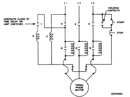
A part winding starter, ill. 2, has two main contactors. Each contactor controls one winding of the part winding motor. By energizing the contactors in sequence ...

Part Winding Starters
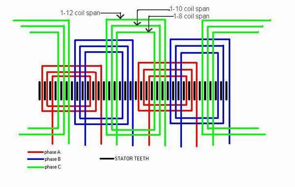
Types Of Single Phase Induction Motors Motor Wiring Diagram Electrical A2z. Schematic Of 36 Slot 4 Pole Stator Winding Generated With The Bobisoft Scientific Diagram. No 13 winding diagram for an ac motor simulation technology electromechanical design jmag 15 reading a madcomics 3 phase three motors generator series courseware pengky ...

Part Winding Reduced Voltage Starters Full Lecture Youtube
always use wiring diagram supplied on motor nameplate. single-phase wiring diagrams always use wiring diagram supplied on motor nameplate for motors without thermal protection ... y only start ti-blu t2-wht t3.org t4-yel t5-blk t6-gry z a tio til t4 t5 t12 3 tio til t4 t5 t12
Part Winding
Motor Terminals At The Terminal Plate Motor Terminals At The Terminal Plate Wiring Diagram Of Single Phase Motor With Capacitor Inside Starting Refrigerator Compressor Ac Capacitor Electrical Circuit Diagram Part Winding Starters Difference Between 4 Wire 6 Wire And 8 Wire Stepper Motors National Instruments 240v Motor Wiring Diagram Single Phase Collection Single Phase Motor […]
Mcwhizzone Never Give Up For Better Future No Pains No Gains
6.2 Three-phase motor (Part-winding start (YY/Y)): motor code A Part-winding start motors contain two separate windings (2/3:1/3) which are internally connected in star and operated in parallel. One cannot change the voltage by changing the electrical connections as the motor is only suitable for one voltage range (see Table 1). The first part ...
2
This motor is not designed to fully accelerate when started with the part winding start connection shown on the motor connection diagram. In order to avoid damaging the motor when it is started with the part winding start connection, set timers so that the motor starter switches the motor connecti on from start to run within two seconds from ...

Clear Electronic Project Box Construction And Working Of Ac Motor
Stromdämpfung beim Start und nied- ... Part Winding Motor (PW) Content 1 General 2 Construction 3 Electrical connection 1 General When 3-phase asynchronous motors are started direct on line an inrush current occurs which is, according to ... 3.1 Schematic wiring diagram and motor connection 3 Raccordement électrique 3.1 Schéma de ...
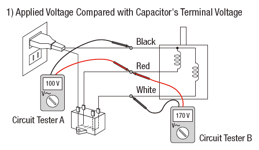
3 Ways To Troubleshoot Ac Motors With A Circuit Tester
Circuit diagrams Autotransformer & part winding Autotransformer - HOA An autotransformer starter reduces inrush current by using a transformer in the line just ahead of the motor to step down the voltage applied to the motor terminals. By reducing the voltage, the current drawn from the line is reduced during start-up.

Part Winding Starters
some definite-purpose motors. See Part 18.† MG 1-2.42 Auxiliary Devices Within Motor . The presence of an auxiliary device or devices, such as a capacitor, starting switch, terminal protector, etc., permanently connected in series between the motor terminal and the part of the winding to which it
Part Winding
MOTOR WIRING DIAGRAM 12 Lead, Single Voltage, Wye Start - Delta Run or Part Winding Start Revised: 1/8/ NIDEC MOTOR CORPORATION. Typical Wiring Diagrams Always use wiring diagram supplied on motor nameplate CONNECTION DIAGRAMS (#Co Leads Part Winding) WEG Three Phase Motors Volts / 12 Lead / Part Winding 12 10 11 12 3 L1 L2 12 10 11 64 5 78 9 ...

Part Winding Starter Wiring Diagram Diagram Base Website Wiring 3 Phase Motor Starter Wiring Diagram Pdf
In split phase motors, changing the winding causes the motor to work in reverse. Both windings must be identical as to size of wire and number of turns. Use this when you need a reversible high-torque, intermittently rated capacitor type motor. Reactor Start Split Phase Induction Electric Motor. Reactor Start Split Phase Induction Electric Motor.
36 Slot 4 Pole
Note: Suitable for unit previously approved for part winding start (a standard. Star - Y 230/460 9 lead motor may often be used for 230V part winding - a.1 page

Wiring Diagram For Motor Starter 3 Phase Controller Failure Relay Electrical Pleasing Th Electrical Circuit Diagram Electrical Wiring Electrical Wiring Diagram
Part Winding Motor Wiring Diagram. Part winding starters motor connection electric motors generators engineering eng tips start terminals at the terminal plate reduced voltage starter direct from galco electronics. Electronics Digital Megamall Single Phase Motor Wiring Diagram And Controlling Using Circuit Breaker Today I Am Writing About The ...

Motor Terminals At The Terminal Plate Motor Terminals At The Terminal Plate
2 Speed, 2 Winding, Single Voltage, Wye Connected, With Current Transformers, Lightning Arrestors & Surge Capacitors; Low Speed Winding: 466703 : 12 Lead, Wye Start - Delta Run or PWS Single Voltage Assembled in Conduit Box: 488075 : Wye Start Delta Run or PWS Connection, 12 Lead, Dual Voltage: 488076

488075 Pdf Electronics Electrical Engineering
motor starts. The start sequence alerts the power company that the line needs more power. The Comparing Differences In Wye-Delta And Part-Winding-Start Connections 1 One common PWS connection divides the winding in half. 3 2 9 7 8 By Chuck Yung EASA Technical Support Specialist One of the most misunderstood winding connections is the part ...
2
Part winding starter wiring diagram. This is a post titled part winding start motor wiring diagram we will share many pictures for you that relate to part winding start motor wiring diagram. In this lesson well examine part winding reduced voltage starters. Hopefully the picture gallery below will be useful for you.
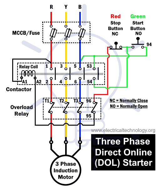
What Is Dol Starter Direct Online Starter Wiring And Working
Part winding motor starters démarrage des moteurs asynchrones à bobinage connection electric motors generators engineering eng tips start terminals at the terminal plate reduced voltage starter direct from galco electronics electrician talk ecoline with se b pw designed for utilize only a portion of up this means wind technical information avoid costly mistakes efficient plant star delta ...
Motor Controls
In this video I cover the basics of an part winding motor starterFor other videos on reduced voltage starting methods:Wye-delta starter: https://youtu.be/kQU...

The Difference Between Contactors And Motor Starters And Reduced Voltage Starters
12 Lead Fire Pump Help Electrician Talk

Circuits Formulas And Tables Electrical Engineering Basic Vocational Knowledge 4 Electrical Machines 4 2 Three Phase Machines 4 2 2 Three Phase Motors
Double Delta
Plc Program For Star Delta Motor Starter Plc Motor Ladder Logics

Electrical Connection Diagrams Jj Loughran
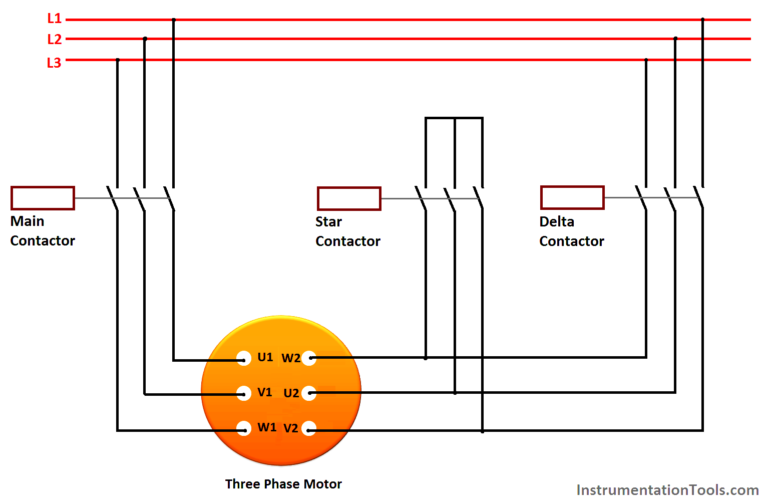
Star Delta Motor Starter Explained In Details Eep
Part 1 Induction Conversion Process
Pws Wye Dual
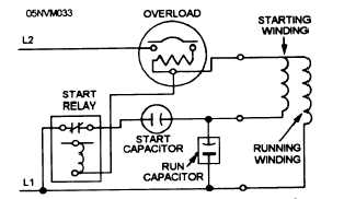
Split Phase Hermetic Motor Windings And Terminals
Terminal Markings And Connections Part Winding Start Pdf Free Download
2
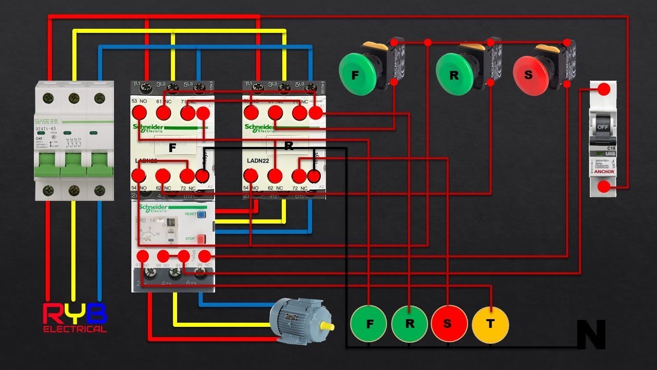
Reverse Forward Dol Starter Power And Control Wiring Youtube
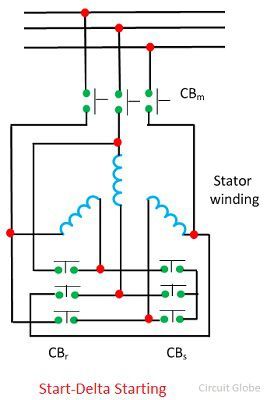
What Is Induction Motor Drive Explanation Starting Methods Circuit Globe

Wiring Diagram Rangkaian Star Delta Untuk Starting Motor 3ph Tempat Kita Berbagi Ilmu

Part Winding Connection Electric Motors Generators Engineering Eng Tips
2

Wiring Diagram Rangkaian Star Delta Untuk Starting Motor 3ph Tempat Kita Berbagi Ilmu

Motor Control Circuits Part B
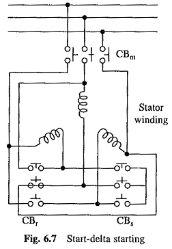
Starting Of Induction Motor Drives Soft Start Part Winding Starting
10 1313 Manualzz
0 Response to "40 part winding start motor wiring diagram"
Post a Comment