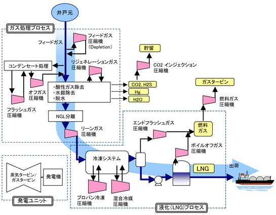
40 lng process flow diagram
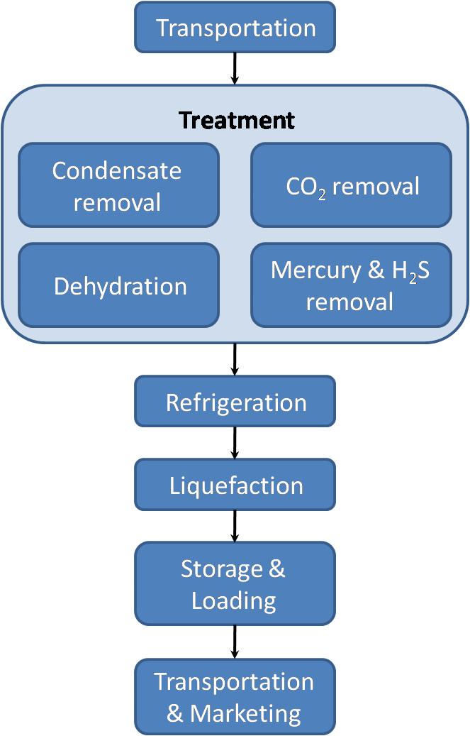
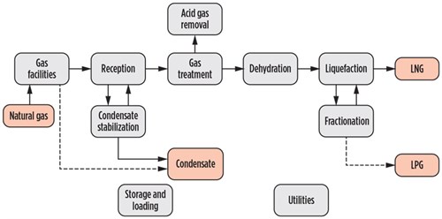
After extraction from the wellheads (Figure 1), the natural gas (NG) is treated with a hydrate inhibitor such as mono-ethylene glycol (MEG) which removes the ... Figure 8: Process flow diagram of R410a precooling-nitrogen expansion liquefaction cycle (He & Ju, 2015) Natural gas flows through two heat exchangers; the first HEX cools the gas down from ambient conditions to -44ºC, where after the second cryogenic HEX produces LNG at -160ºC.
34-year veteran of the gas process-ing, gas treating, and liquefied natural gas (LNG) industry. As a senior advisor for Chevron’s Energy Technology Company, he has served as the Process Manager/ Process Lead for many projects, including the Wheatstone LNG, Gorgon LNG, Delta Caribe LNG, Casotte Landing, and Sabine Pass LNG terminal projects.
Lng process flow diagram
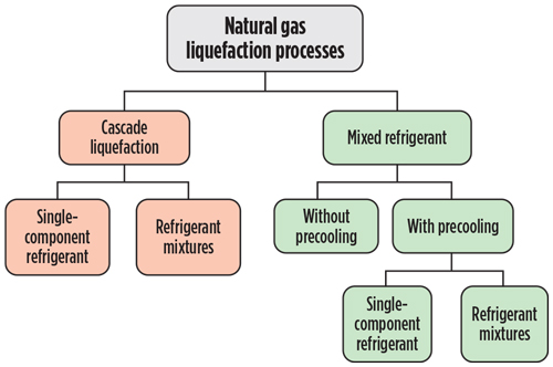
by IS Al-Mutaz — Gas liquefaction processes are differentiated mainly by the type of refrigeration cycle employed. Fig. 2. LNG block flow diagram. GP0617 Al Mutaz LNG Fig 2 ... 2 x 14 units on Q-Max LNG carriers. In operation since 2008, 187 tpd 2 x 4 units to MOL for PNG LNG project, operational from 2015 6 Process flow diagram for boil off gas re-liquefaction onboard tankers A Q-Max LNG carrier with 266’000 m3 of LNG cargo capacity, arrives in the UK to unload its cargo. IMAGE QatarGas BOG Compressor BOG ... Process automation end users are under more pressure than ever to do more with less. The current economic climate means that many automation capital projects are on hold. With capital budgets tighter than ever, users instead focus on operational budgets (where cost cutting is also a key concern), or on automation investments with a very rapid return on investment.
Lng process flow diagram. II. The Process A simplified process flow diagram is shown in Figure 1. Figure 1 – LNG Receiving Terminal Simplified Process Flow Diagram The LNG receiving terminal receives liquefied natural gas from special ships, stores the liquid in special storage tanks, vaporises the LNG, and then delivers the natural gas into a distribution pipeline. The following is a general guideline for the startup for an LNG production plant. A generic C3MCR liquefaction train process flow diagram is shown in Figure 7-2.Startup of other liquefaction technologies may be slightly different. T-Q Diagrams The main goal is to reduce the distance between the two curves. This would signify a reduction in the work during the cooling process and an increase in efficiency. Download scientific diagram | Simplified process flow diagram of AP-X LNG process. from publication: Comparative Well-to-Tank energy use and greenhouse gas ...
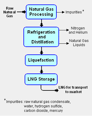
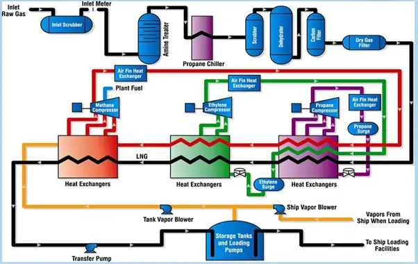
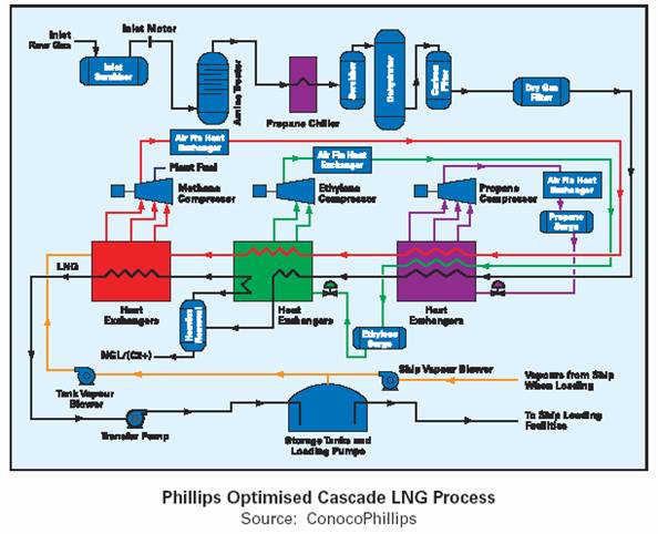
•At atmospheric pressure LNG has a temperature of about –162ºC •LNG contains about 85-95 % methane •LNG is colorless, odorless, non-corrosive and non-toxic •Evaporated LNG can displace oxygen and cause human suffocation •Flammability range, 5-15 vol % concentration in air •Autoignition temperature, 540 C 5 LNG is a cryogenic liquid Download scientific diagram | 6 Block Flow Diagram of an LNG plant. from publication: Simulation and integration of liquefied natural gas (lng) processes ... 22.07.2015 · Nitrogen gas (N2) is a colorless, odorless gas which makes up roughly 78% of the earth’s atmosphere. It is used in industry as a simple asphyxiant with inerting quality making it useful in many applications where oxidation is not desired. N2 as an industrial gas is produced (generated) by one of the following means: Fractional distillation of liquid air (from […] Liquefied Natural Gas (LNG) For the 2014 SPE Roughneck Camp Chris Caswell, Director – LNG and FLNG KBR July 17, 2014 . ... Process Flow Diagram Q High Temperature (Ambient) Q Low Temperature (Sub - Ambient) Condenser Suction Drum Compressor Heat Exchanger J-T Valve
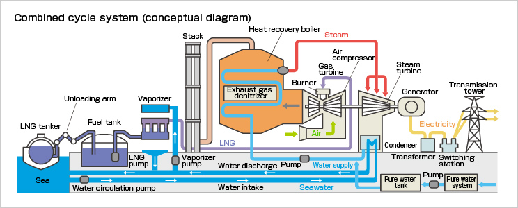
Liquefied Natural Gas (LNG) is Natural Gas that has been cooled to –260° F (–162° C), changing it from a gas into a liquid that is 1/600th of its original vo... Liquid cargo storage tanks of liquefied natural gas (LNG) carriers are designed by strict standards to maintain the cryogenic state (−163 °C). For most LNG ... 03.12.2019 · Last updated: December 3, 2019 Google Fusion Tables and the Fusion Tables API have been discontinued. We want to thank all our users these past nine years. We understand you may not agree with this decision, but we hope you'll find alternatives that are just as useful, including BigQuery, Cloud SQL, Maps Platform, and Data Studio. ... storage tanks, which takes approximately 14-16 hours. The LNG remains at -160°C for the duration of the process. LNG has been transported commercially by ships since 1964 and as of the end of 2016 there have been 88,000 cargoes or 176,000 voyages without an LNG loss. T. ransPorTaTion. A 155,000 m. 3. membrane vessel is approximately the same ...
1
V - volume flow of compressed air at atmospheric pressure (cfm, ft 3 /min) k - adiabatic expansion coefficient . P 2 - absolute final pressure (psi) Make a Shortcut to this Calculator on Your Home Screen? Theoretical horsepower required to compress one cubic foot of free air (atmospheric pressure) for single-staged, two-staged and three-staged compressors are indicated in the diagram below. In ...
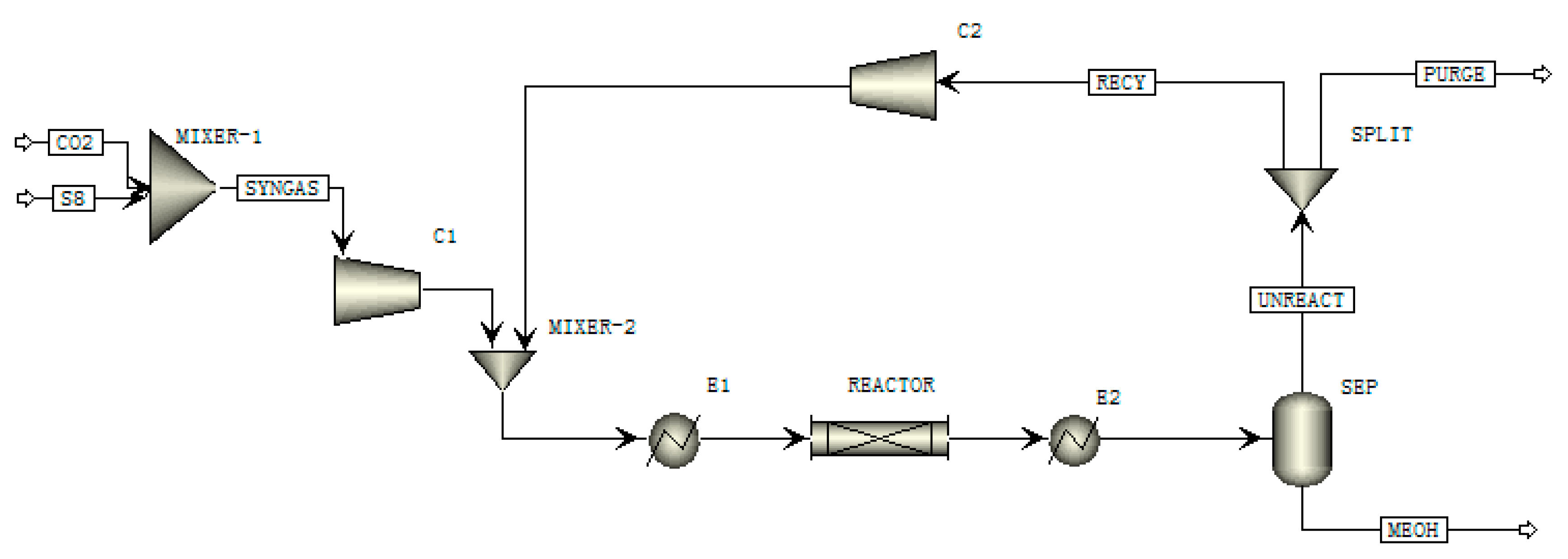
Processes Free Full Text Modeling And Analysis Of Coal Based Lurgi Gasification For Lng And Methanol Coproduction Process Html
Hammerfest LNG plant - block flow diagram. Slug catcher. Inlet facilities/ ... process. – Typical requirements for LNG: Max 50 ppmv CO2, Max 4 ppmv H2S.28 pages

An Introduction Into The Air Products And Chemicals Inc Mixed Refrigerant Lng Liquefaction Process What Is It And How Does It Work Campbell Tip Of The Month
Liquefied Natural Gas or LNG is natural gas with the primary element as methane. ... 5 shows a Schematic of a Simple Refrigeration Cycle (LNG Process Flow) ...

Lng Fundamentals Sciencedirect
Air Compressors - Maximum Air Flow at Inlet Pipes . Inlet pipe size and maximum air flow. Air Discharge through Hoses . Discharging air volume through hoses at pressures ranging 30 - 90 psi. Air Properties - Imperial Units . Thermodynamic properties of air at low pressures - imperial units. Air Specific Heat Ratio

Lng Gas Plants Problems And Solutions Campbell Tip Of The Month
Process automation end users are under more pressure than ever to do more with less. The current economic climate means that many automation capital projects are on hold. With capital budgets tighter than ever, users instead focus on operational budgets (where cost cutting is also a key concern), or on automation investments with a very rapid return on investment.

Control System Natural Gas Liquefication Process Lng
2 x 14 units on Q-Max LNG carriers. In operation since 2008, 187 tpd 2 x 4 units to MOL for PNG LNG project, operational from 2015 6 Process flow diagram for boil off gas re-liquefaction onboard tankers A Q-Max LNG carrier with 266’000 m3 of LNG cargo capacity, arrives in the UK to unload its cargo. IMAGE QatarGas BOG Compressor BOG ...
2
by IS Al-Mutaz — Gas liquefaction processes are differentiated mainly by the type of refrigeration cycle employed. Fig. 2. LNG block flow diagram. GP0617 Al Mutaz LNG Fig 2 ...

How Does Regasification Of Lng Work

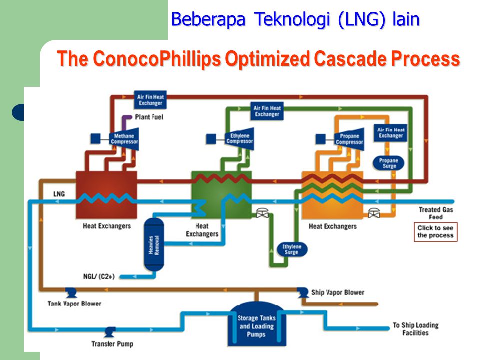
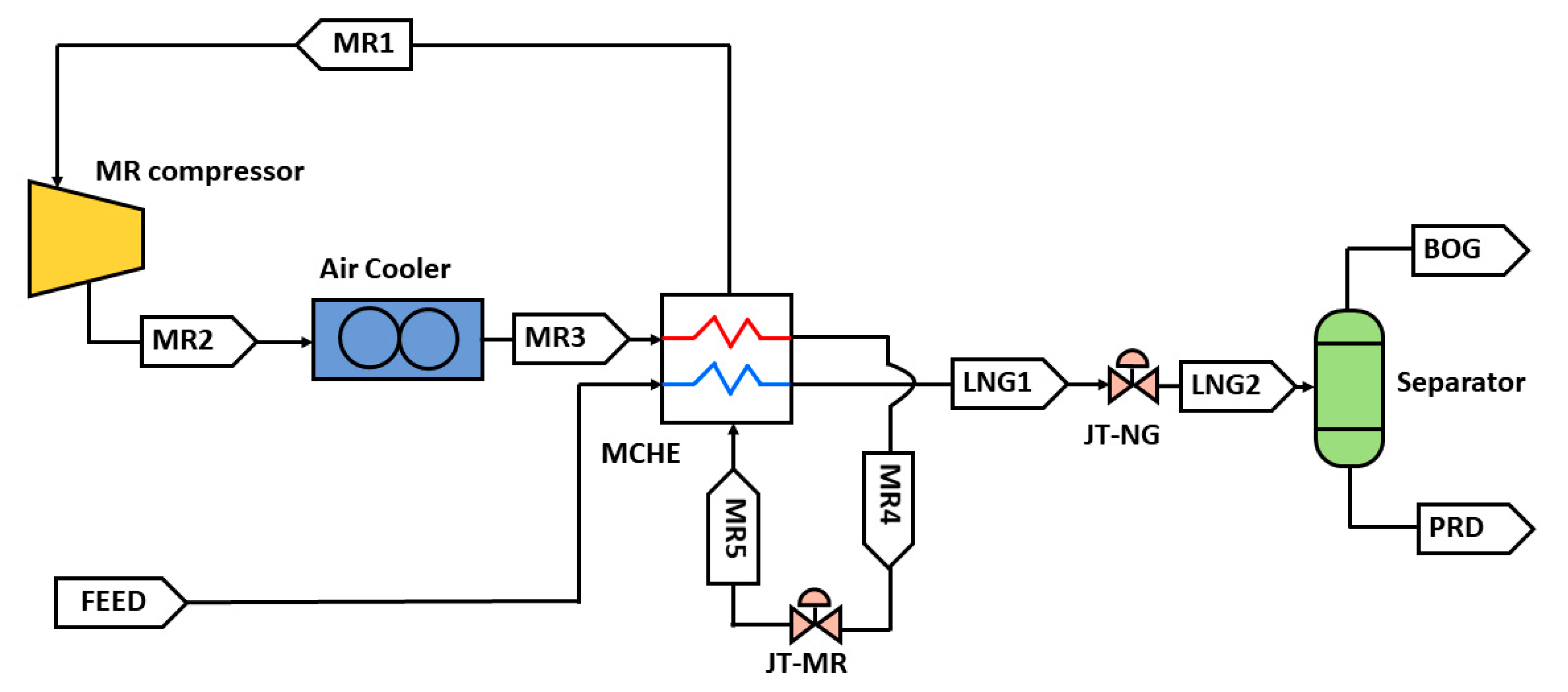
The Apci C3 Mr Process Part 2
Liquefied Natural Gas Encyclopedia Article Citizendium
Proses Pembuatan Lng Dr Ir Slamet Mt Ppt Download

A Generalized Natural Gas Industry Process Flow Diagram That Goes From The Well To The Consumer Gas Industry Gas Oil And Gas
2
1
Chpt 4 Natural Gas And Lng Tech

Simplified Process Flow Diagram For The Operating Lng Train Co 2 Download Scientific Diagram

Proses Umum Pembuatan Lng Di Pt Badak Ngl Candra A Wiguna
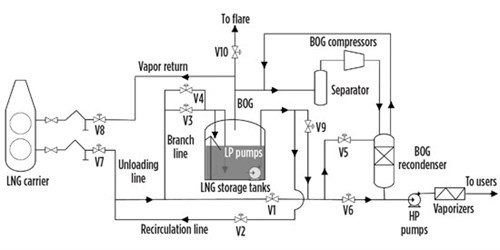
Optimization Of Bog Management During Lng Unloading With Dynamic Simulation
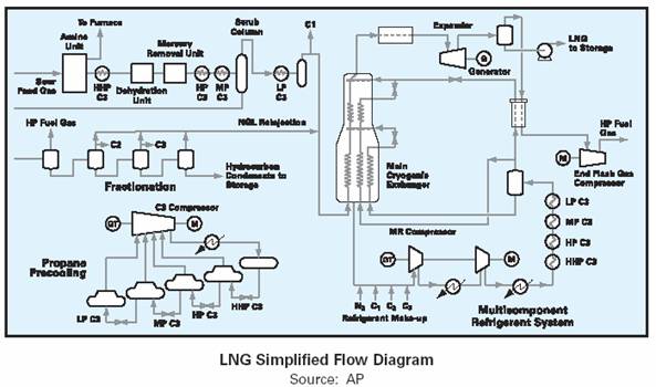
Process Selection And Recent Design Innovations For Lng Plants Part 1

Lng Gas Plants Problems And Solutions Campbell Tip Of The Month

Flowchart For Lng Plant With Two Trains Download Scientific Diagram

Process Flow Diagram Of The Energy Storage System Including The Lng Download Scientific Diagram

Flow Diagram Of Lng Process Download Scientific Diagram

6 Block Flow Diagram Of An Lng Plant Download Scientific Diagram
Solved 1 Make A Process Flow Diagram From The Image 2 Chegg Com
Liquefied Natural Gas Wikipedia
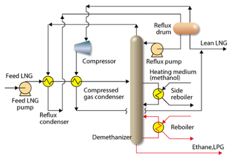
High Efficient Ngl Lpg Recovery Process Coreflux Toyo Engineering Corporation
Process Selection And Recent Design Innovations For Lng Plants Part 1
Liquified Natural Gas Properties Uses Origin Composition Lng Process What Is Piping
2
Chpt 4 Natural Gas And Lng Tech
Mitsubishi Heavy Industries Compressor Corporation Lng Floating Lng
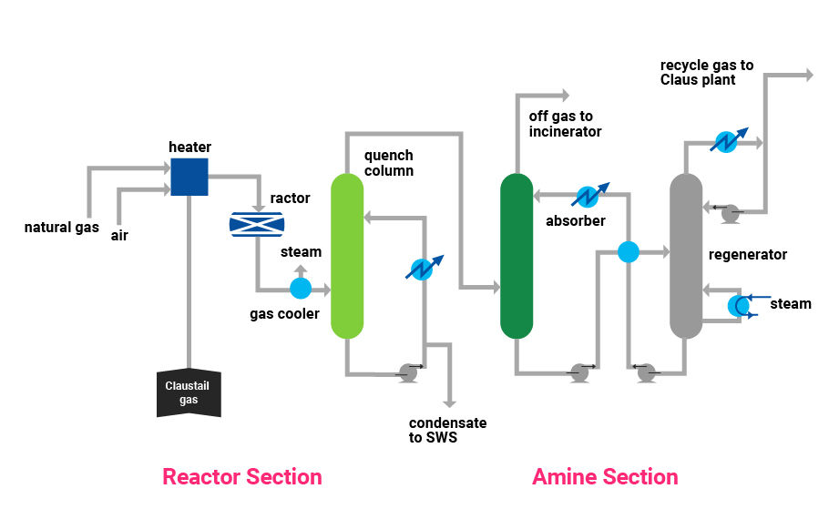
Tail Gas Treating Tgt Chiyoda Corporation
Applied Sciences Free Full Text Optimization And Economic Analysis For Small Scale Movable Lng Liquefaction Process With Leakage Considerations Html

The Apci C3 Mr Process Part 2

6 Block Flow Diagram Of An Lng Plant Download Scientific Diagram

Simplified Process Flow Diagram For The Study Case Lng Co 2 Absorption Download Scientific Diagram
2

Largest Tokyo Gas Lng Terminal Sodegaura Chandra S Blog
Process Flow Of A Typical Lng Receiving And Regasification Terminal Download Scientific Diagram
0 Response to "40 lng process flow diagram"
Post a Comment