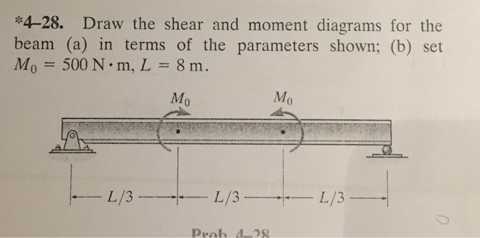
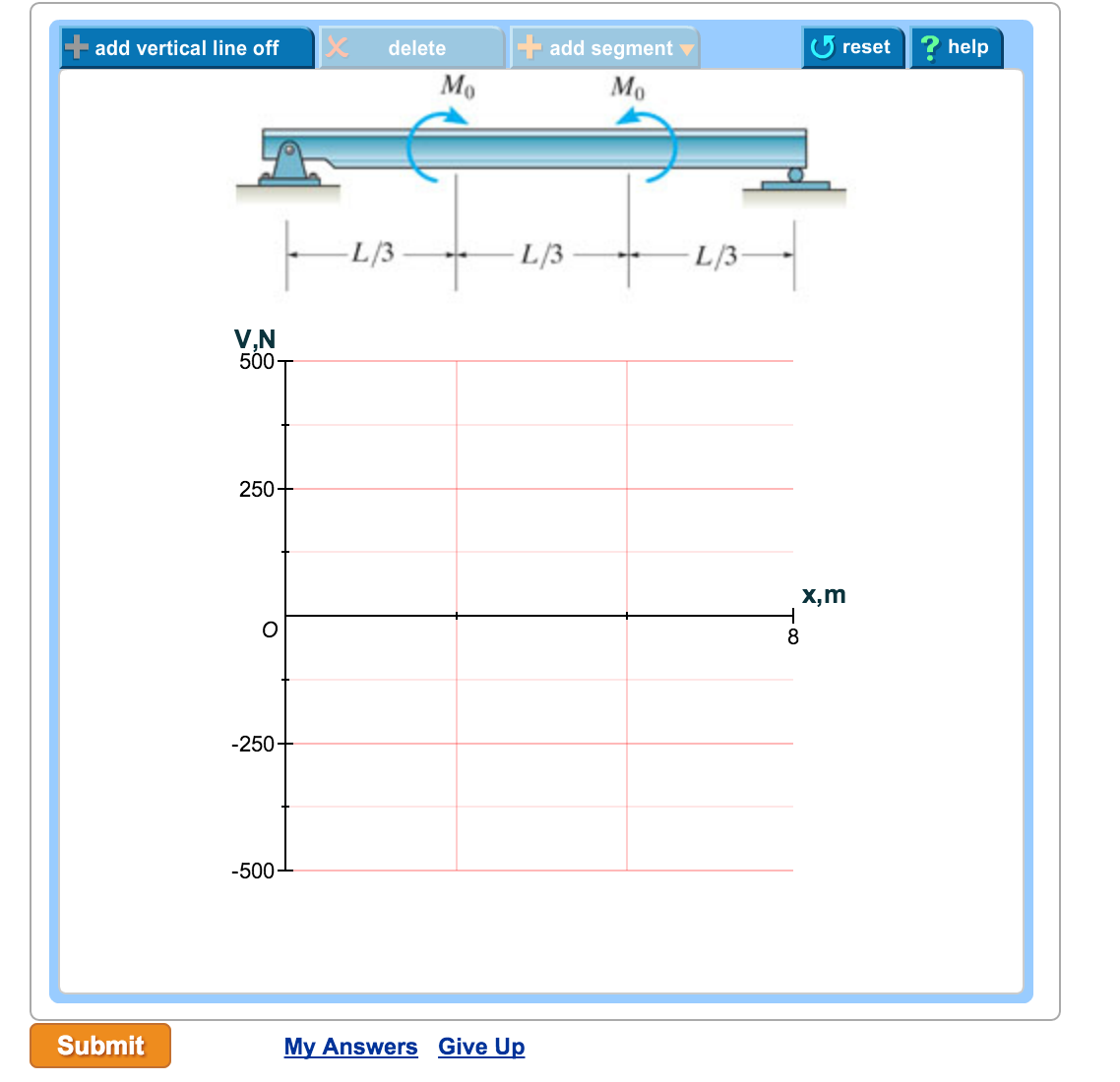
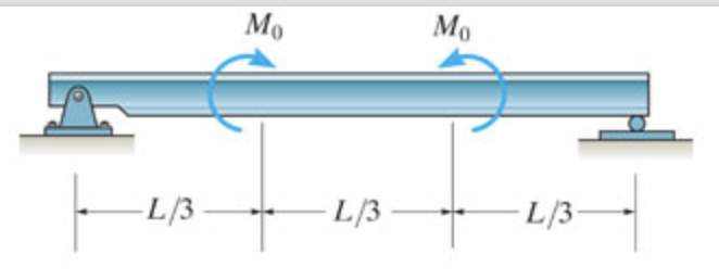
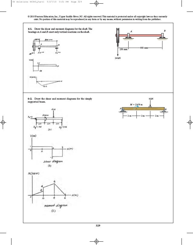
39 draw the shear diagram for the beam. set m0 = 500 n⋅m, l = 8 m.
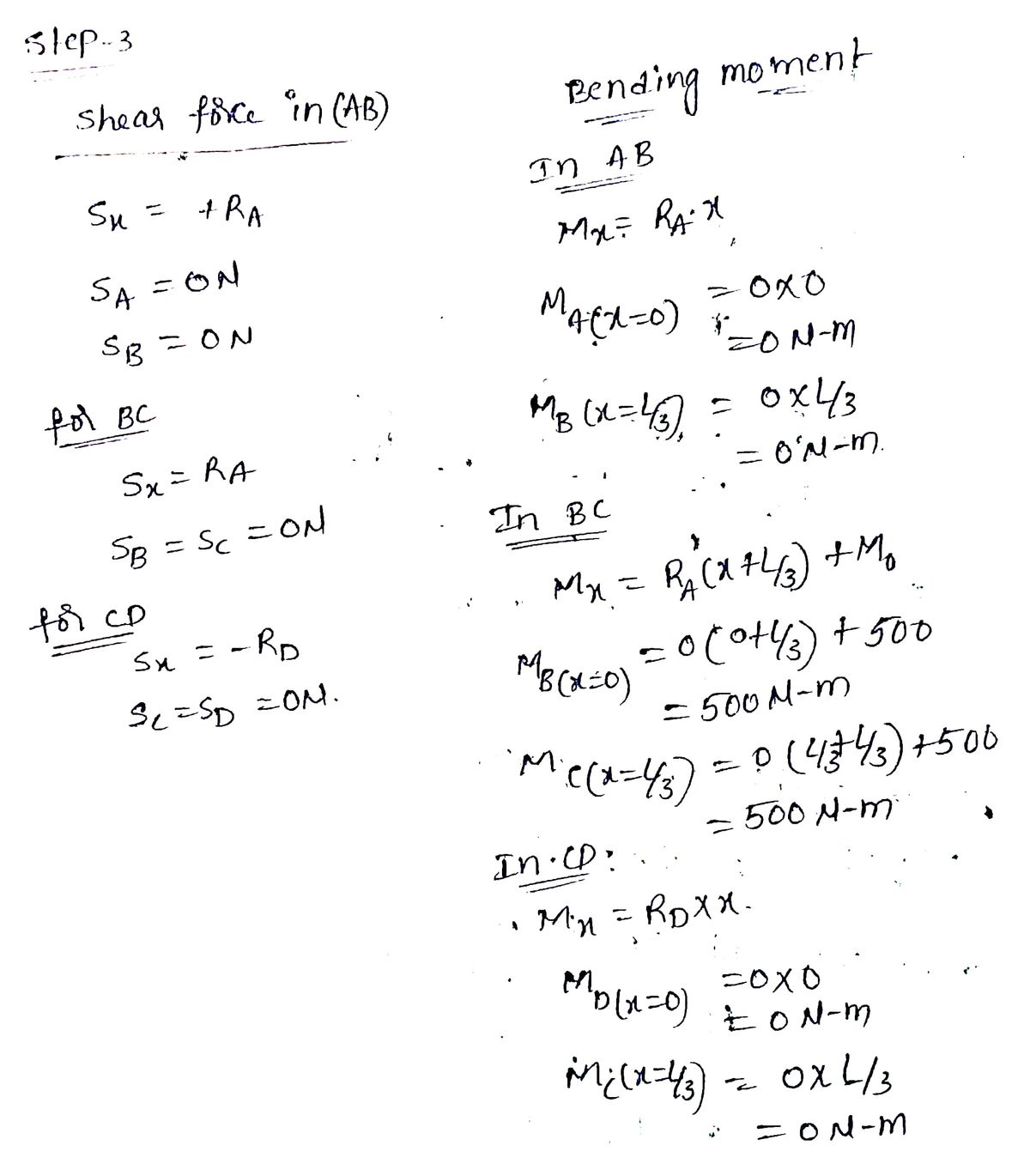
BEAM DIAGRAMS AND FORMULAS Table 3-23 (continued) Shears, Moments and Deflections 13. BEAM FIXED AT ONE END, SUPPORTED AT OTHER-CONCENTRATED LOAD AT CENTER Then, draw the shear force diagram (SFD) and bending moment diagram (BMD). b) If P = 20 kN and L = 6 m, draw the SFD and BMD for the beam. P kN L/2 L/2 A B EXAMPLE 4 . P kN L/2 L/2 R Ax R Ay R By By taking the moment at A:
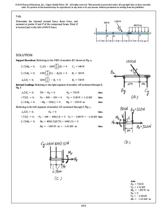
desirable to draw the V-diagram below the FBD of the entire beam, and then draw the M-diagrambelow the V-diagram. The bending moment and shear force diagrams of the beam are composites of the V and M diagrams of the segments. These diagrams are usually discontinuous, or have discontinuous slopes.
Draw the shear diagram for the beam. set m0 = 500 n⋅m, l = 8 m.
Solution for Draw the shear diagram for the beam. Set Mo = 500 N⋅m, L = 8 m. Draw the moment diagram for the beam. Set Mo = 500 N⋅m, L = 8 m. V = 200 N 0 … x 6 3 m 6–35. Draw the shear and moment diagrams for the beam and determine the shear and moment as functions of x. 3 m 3 m x AB 200 N/m 400 N/m Ans: M = e - 100 9 x 3 + 500x - 600f N # m For 3 m 6 x … 6 m: V = e - 100 3 x2 + 500f N, For 0 … x 6 3 m: V = 200 N, M = (200x) N # m, x (m) V (N) 0 200 0 3 3.87 3 3.87 600 691 6 ... shear, so too we will use the same moment/curvature relationship to produce a dif-ferential equation for the transverse displacement, v(x) of the beam at every point along the neutral axis when the bending moment varies along the beam. Mb EI -d s dφ = The moment/curvature relation-ship itself is this differential equa-tion.
Draw the shear diagram for the beam. set m0 = 500 n⋅m, l = 8 m.. B set m0 and l as given. Draw the shear diagram for the beam. set m0 = 500 n⋅m, l = 8 m.. Shear and moment diagrams consider a simple beam shown of length l that carries a uniform load of w nm throughout its length and is held in equilibrium by reactions r 1 and r 2. B set p800lb a5ft l12ft. Draw the shear diagram for the beam. Transcribed image text: Draw the shear and moment diagrams for the beam (a) in terms of the parameters shown; (b) set M_0 = 500 N middot m, L = 8 m.Missing: ⋅ | Must include: ⋅ determining the maximum bending stress in a prismatic beam: •Draw the bending moment diagram by one of the methods described in Chapter 4. Identify the bending moment M ... I m M N m y m N m ⋅ σ = Sample Problem 5.1 The simply supported beam in Fig. (a) has a rectangular cross ... The shear force and bending moment diagrams. M max = +16 kN ... 14:03This is an example problem that will show you how to graphically draw a shear and moment diagram for a ...3 May 2020 · Uploaded by structurefree
Set M0 = 500 N?m, L = 8 m. 2. Draw the moment diagram for the beam. Thanks for the help! add vertical line off ... Set M0-500 N·m, L-8 m. Click on "add discontinuity" to add discontinuity lines. Then click on "add segment" button to add functions between the lines. add vertical line off delete add segment reset ? help Mo Mo L/3 V,N 500 250 x,m 8 -250 500 ; Question: Part A Draw the shear diagram for the beam. Set M0-500 N·m, L-8 m. problem 7-48 R.C.Hibbeler book. Draw the shear and moment diagrams for the beam. (a)in the terms of the parameters shown. (b) set M_0= 500Nm and L= 8. M max ... Set M_0 = 500 N middot m, L = 8 m.(Figure 1) Identify the shear diagram. Identify the moment diagram. Submit. This problem has been solved!Missing: draw | Must include: draw
Draw a free-body diagram of the segment {0≤x<;8 ft} on paper and calculate the internal shear, V, and moment, M, over this segment. Express your answers as ... Problem 7.46 Part A Draw the shear diagram for the beam. Set Mo = 500 N·m, L = 8 m. Click on "add discontinuity" to add discontinuity lines. Then click on "add segment" button to add functions between the-imes. add vertical line off + add segment σ reset ? help delete Mo Mo L/3 V,N 500 250 x,m -250 -500 Submit My Answers Give Up shear, so too we will use the same moment/curvature relationship to produce a dif-ferential equation for the transverse displacement, v(x) of the beam at every point along the neutral axis when the bending moment varies along the beam. Mb EI -d s dφ = The moment/curvature relation-ship itself is this differential equa-tion. V = 200 N 0 … x 6 3 m 6–35. Draw the shear and moment diagrams for the beam and determine the shear and moment as functions of x. 3 m 3 m x AB 200 N/m 400 N/m Ans: M = e - 100 9 x 3 + 500x - 600f N # m For 3 m 6 x … 6 m: V = e - 100 3 x2 + 500f N, For 0 … x 6 3 m: V = 200 N, M = (200x) N # m, x (m) V (N) 0 200 0 3 3.87 3 3.87 600 691 6 ...
Statics And Dynamics 10th Ed Johnston
Solution for Draw the shear diagram for the beam. Set Mo = 500 N⋅m, L = 8 m. Draw the moment diagram for the beam. Set Mo = 500 N⋅m, L = 8 m.
2

300 Solved Problems In Geotechnical Engineering Pdf Deep Foundation Foundation Engineering
Solved Draw The Shear And Moment Diagrams For The Beam A Chegg Com

Mechanics Of Materials Pages 201 250 Flip Pdf Download Fliphtml5
Chapter 7
2
2
Beermom Ge C09 P001 P
2
Solved 1 Draw The Shear Diagram For The Beam Set M0 500 Chegg Com

Fundamentals Of Engineering Supplied Reference Handbook
2
Dyp Gre Mdm 7e Eng
Solution To Problem 405 Shear And Moment Diagrams Strength Of Materials Review At Mathalino
Solved 5 3 Shear And Moment Diagram Practice Problems Draw Chegg Com
2

7 55 Draw The Shear And Moment Diagrams For The Beam 80 Kn M Prob 7 55 Homeworklib
2

Draw The Shear And Moment Diagrams For The Beam A In Terms Of The Parameters Shown B Set Mo 500 N M L 8 M Study Com
2

Solved Part A Draw The Shear Diagram For The Beam Part B Draw The Moment 1 Answer Transtutors

Local Failures Of Coped Steel Beams A State Of The Art Review Sciencedirect

Mechanics Of Materials By Andrew Paytel Pdf Bending Stress Mechanics
Answered Draw The Shear Diagram For The Beam Bartleby
Solved Manila Ek 3 Question 2 107 Draw The Shear And Chegg Com

Find The Distribution Asfunctions Of Xl Of The Noripal N And Shear Wi Forces And Moment M For The Beam Shown In The Figure X I Pdf Free Download

Draw The Shear Diagram For The Beam Set M0 500 Nm L 8 M Wiring Site Resource
Solved Draw The Shear And Moment Diagrams For The Shaft A In Terms Of The Parameters Shown B Set P 9 Mathrm Kn A 2 Mathrm M L 6 Mathrm M There Is A Thrust Bearing At A
Problem 1 Using Graphical Method Draw The Shear And Bending Moment Diagrams For The Beam Shown In The Figure Determine The Absolute Maximum Bending Ppt Video Online Download
2
2

Problem 1 Using Graphical Method Draw The Shear And Bending Moment Diagrams For The Beam Shown In The Figure Determine The Absolute Maximum Bending Ppt Video Online Download

Draw The Shear And Moment Diagrams For The Beam A In Terms Of The Parameters Shown And B Set M0 500 N M L 8m Study Com
2

Saze808 Touching Structural Concept By Mojtaba Asghari Issuu
Ch06 07 Pure Bending Amp Transverse Shear

Pdf 7 Solutions 44918 Adriano Cruz Academia Edu
Answered Draw The Shear Diagram For The Beam Bartleby
0 Response to "39 draw the shear diagram for the beam. set m0 = 500 n⋅m, l = 8 m."
Post a Comment