38 iron iron carbide diagram
The binary iron carbon equilibrium diagram is the basis of steel and cast iron. It concerns transformations that occur in alloys having compositions from pure iron to cementite (6.67 per cent carbon). There are two versions of iron carbon equilibrium diagram : 1. Iron-cementite system. Iron carbide (Fe 3 C) is often labeled as the uncorroded portion of the steel. It is primarily associated with mild steels having a high carbon content and a ferritic-pearlitic microstructure. During corrosion of such steel, the ferrite phase dissolves and a porous iron carbide network is exposed (see Fig. 7.6).Given that iron carbide is an electronic conductor, this porous network serves as ...
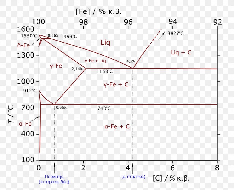
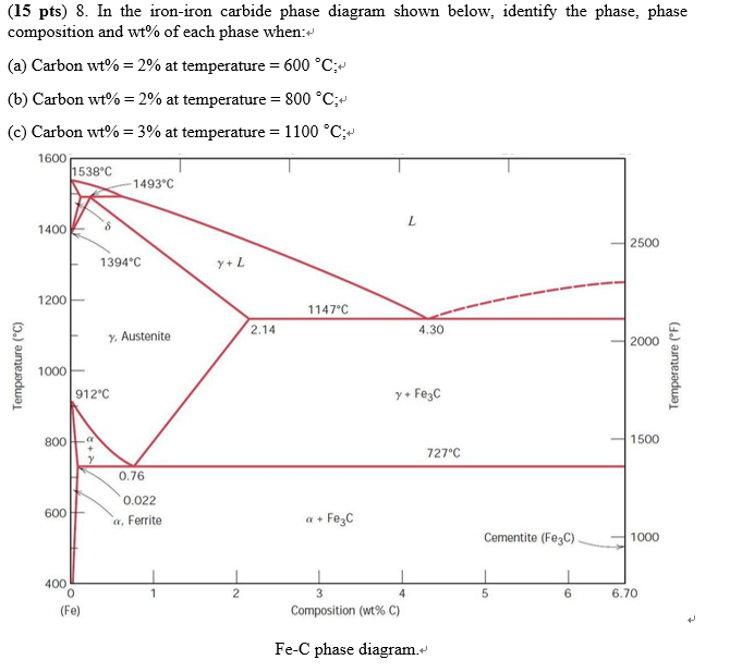
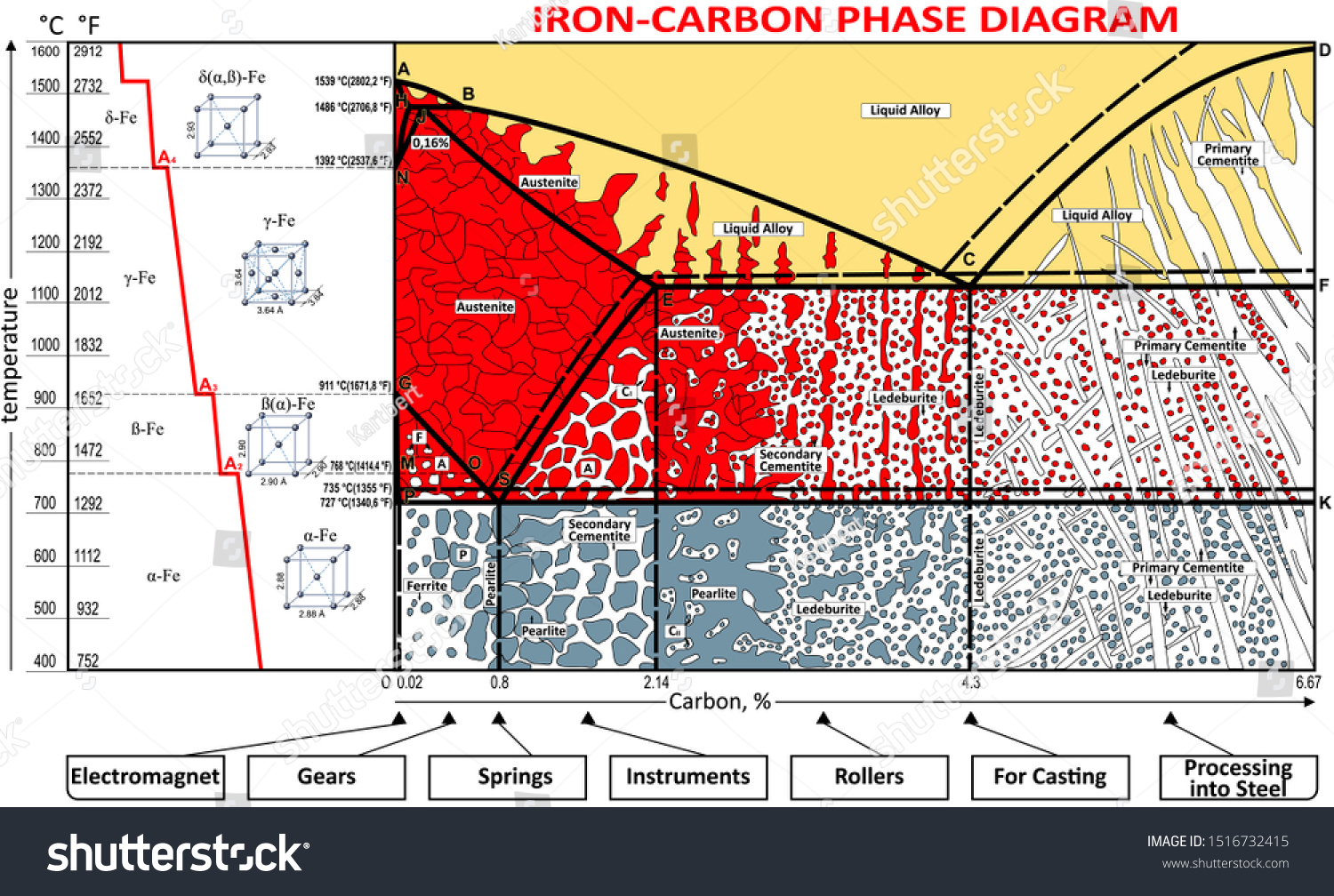
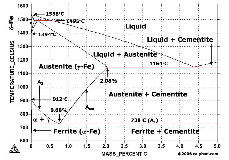
In the figure, there is the iron-iron carbide (Fe-Fe3C) phase diagram. The percentage of carbon present and the temperature define the phase of the iron carbon alloy and therefore its physical characteristics and mechanical properties. The percentage of carbon determines the type of the ferrous alloy: iron, steel or cast iron.
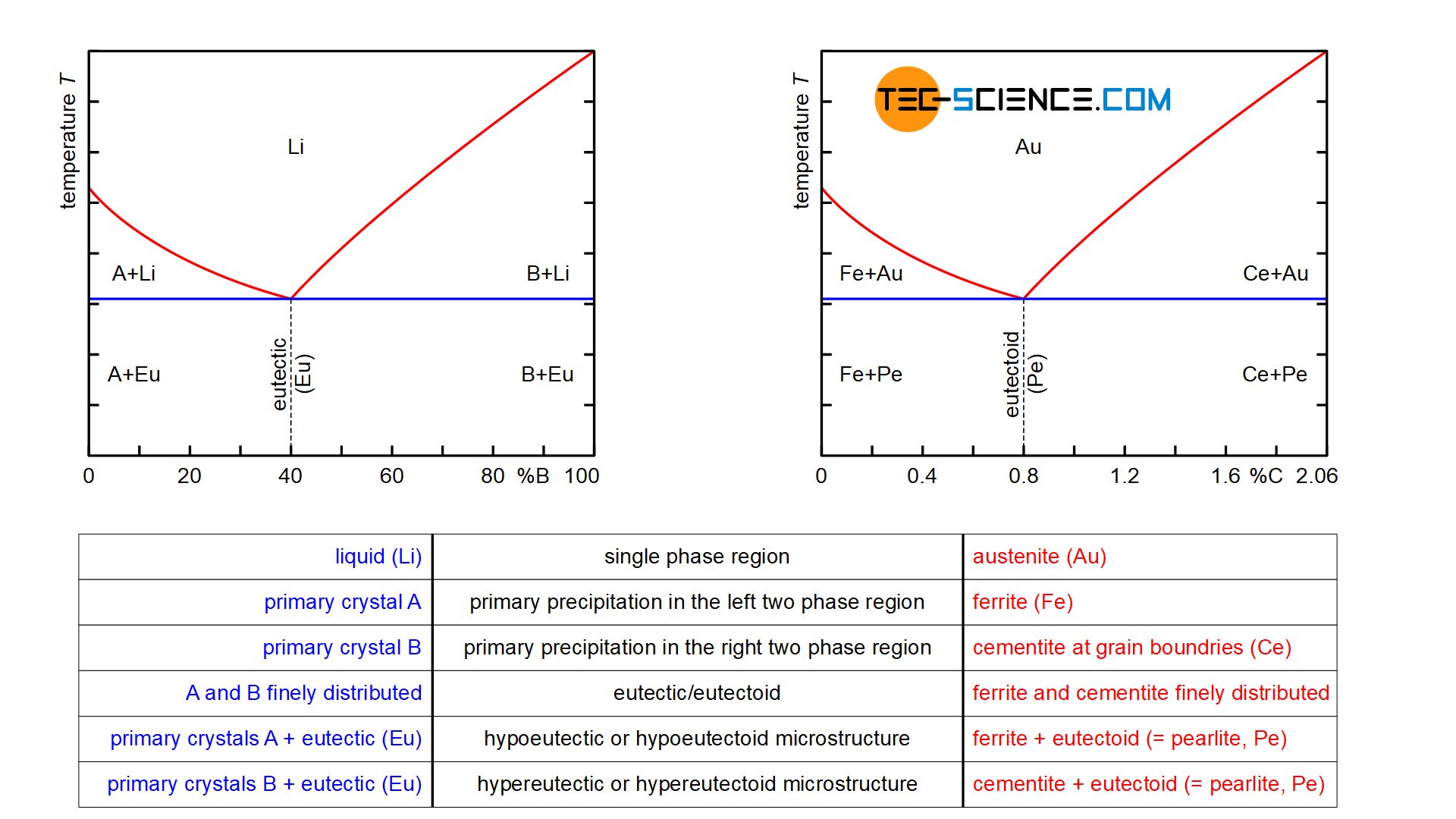
Iron iron carbide diagram
The iron-carbon diagram. It should first be pointed out that the normal equilibrium diagram really represents the metastable equilibrium between iron and iron carbide (cementite). Cementite is metastable, and the true equilibrium should be between iron and graphite. Although graphite occurs extensively in cast irons (2-4 wt % C), it is usually ... The iron-iron carbide (Fe-Fe3C) phase diagram Microstructures of iron α- ferrite austenite. 2 Interstitial sites of FCC Interstitial sites of BCC. 3 Microstructure in iron-carbon alloys REutectic--pearlite Hypoeutectoid alloys. 4 Hypereutectoid alloys Equilibrium diagrams having intermediate phases or compounds Iron-Iron Carbide Phase Diagram Example . Fig 1: Fe-Fe 3 C Phase Diagram (clickable), ... 1988 . Figure 1 shows the equilibrium diagram for combinations of carbon in a solid solution of iron. The diagram shows iron and carbons combined to form Fe-Fe 3 C at the 6.67%C end of the diagram. The left side of the diagram is pure iron combined with ...
Iron iron carbide diagram. The Iron-Iron Carbide Diagram. The iron-carbon composite scheme diagram portion between plain iron and an interstitial compound, iron carbide (Fe3C), comprising 6.67 percent by weight is called iron-iron carbide balance diagram. It may be observed that although it is called as a diagram of equilibrium, it is not a real diagram of equilibrium ... So let's start with a phase diagram that contains maximal information: A 1: The upper limit of the ferrite / cementite phase field (horizontal line going through the eutectoid point). A2: The temperature where iron looses its magnetism (so-called Curie temperature ). Note that for pure iron this is still in the α -phase. The iron-iron carbide (Fe-Fe 3C) phase diagram Ferrite-α-BCC, low C solubility(0.022%wt), magnetic Austenite-γ-FCC, high C solubility(2.14%wt), nonmagnetic Ferrite-δ-BCC Cementite (Fe 3C) Eutectic, peritectic, eutectoid Iron, ferrite (C<0.008wt%) Stainless steel, α+Fe 3C (0.008-2.14wt%) Microstructures of iron α-ferrite austenite The Iron-Carbon Phase Diagram. satyendra; March 11, 2013; 10 Comments ; bcc, cementite, critical temperature, fcc, Ferrite, heat treatment of steels, Martensite, micro structure, pearlite, phase, phase diagram,; The Iron-Carbon Phase Diagram. The phase diagrams are very important tools in the study of alloys for solutions of many practical problems in metallurgy.
Iron-Carbon Phase Diagram with Detailed Explanation: If the percentage of the carbon is in the range of 0 to 2.11 % then it is called Steel and if the percentage of carbon is in the range of 2.11 to 6.67% then it is called Cast iron. As the carbon content increases, it produces more Iron-Carbide volume and that phase will exhibit high hardness. Answer (1 of 2): The Iron Carbide diagram is the most important one to study the behavior of iron and alloys of iron (steels) in particular. It will provide a valuable foundation to build knowledge of large variety of both plain carbon steels and alloy steels. It forms the basis of commercial ste... Iron carbide is the second phase which is formed when carbon exceeds the limit of solubility which defines the point where the solubility of C in the Fe is at its maximum as shown in the Fe-C phase diagram in Fig 2, which is a graph of the balance for the combinations of C in a solid solution with iron. The Iron-Iron Carbide Diagram. The part of iron-carbon alloy system diagram between pure iron and an interstitial compound, iron carbide (Fe 3 C), containing 6.67 percent carbon by weight is called iron-iron carbide equilibrium diagram. It may be noted that though it is called as equilibrium diagram, it is not a true equilibrium diagram, since ...
Short video on how to draw iron-Iron carbide equilibrium diagram. For full video with fun click: https://www.youtube.com/watch?v=URabBdX7sfo&t=23s Cementite or Iron carbide. To form cementite or iron-carbide, we need to have a fixed amount of carbon and a fixed amount of carbon, and that's the reason why this is known as the metastable phase of this alloy. It contains 6.67% of carbon, and it is an extremely hard and brittle compound having very low tensile strength. C (iron carbide or cementite) •This intermetallic compound is metastable at room T. It decomposes (very slowly, within several years) into α‐Fe and C (graphite) at 650 ‐700 °C ¾Fe‐C liquid solution The part of iron-carbon alloy system diagram between pure iron and an interstitial compound, iron carbide (Fe3C), containing 6.67 percent carbon by weight is called iron-iron carbide equilibrium diagram. In fact, the compound iron carbide decomposes into iron and carbon (graphite). What does the iron carbon phase diagram show?
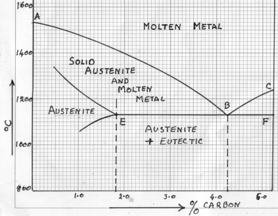
This iron carbon phase diagram is plotted with the carbon concentrations by weight on the X-axis and the temperature scale on the Y-axis. The carbon in iron is an interstitial impurity. The alloy may form a face centred cubic (FCC) lattice or a body centred cubic (BCC) lattice. It will form a solid solution with α, γ, and δ phases of iron.
(iv) Cementite, Iron Carbide, Fe 3 C: It is an interstitial intermediate compound having a fixed carbon content of 6.67%. It has a complex orthorhombic crystal structure with 12 iron atoms and 4 carbon atoms per unit cell. It is a compound with high hardness (~ 800 VPN), which easily scratches the glass. It is brittle phase with low tensile ...
• Cementite or iron carbide, is very hard, brittle intermetallic compound of iron & carbon, as Fe3C, contains 6.67 % C. • It is the hardest structure that appears on the diagram, exact melting point unknown. • It is has - low tensile strength (approx. 5,000 psi), but - high compressive strength.
The iron-iron carbide phase diagram is shown in the Animated Figure 10.28. Question: Compute the mass fraction of eutectoid ferrite in an iron-carbon alloy that contains 0.55 wt% C. The iron-iron carbide phase diagram is shown in the Animated Figure 10.28. This problem has been solved!
THE IRON-IRON CARBIDE DIAGRAM A map of the temperature at which different phase changes occur on very slow heating and cooling in relation to Carbon, is called Iron- Carbon Diagram. Iron- Carbon diagram shows the type of alloys formed under very slow cooling, proper heat-treatment temperature and how the properties of steels and cast irons can ...
IRON- IRON CARBIDE SYSTEM (FE - FE₃C DIAGRAM) Both steels and cast irons, primary structural materials in every technologically advanced culture, are essentially iron-carbon alloys. Iron-carbon phase diagram shown in figure is not a complete diagram. Part of the diagram after 6.67 wt% C is ignored as it has little commercial significance.
Transcribed image text: 3. (3pts) Consider an iron-carbon alloy an answer parts a-c. Below is the equilibrium iron-iron carbide phase diagram. Competition 10 1580 14930 15 25 1600 1400 2500 13940 1200 3147 2.14 4.10 2000 Ades Tento 1000 Tome Teg 9120 1500 7270 0.16 0.002 fen 500 Cerretes 1000 6.70 400 O tel Comic Adapted fry All Dia Music (a) Using the isothermal transformation diagram for a 0 ...
Iron carbide is called metastable phase. The temperature at which the allotropic changes takes place in iron is influenced by alloying elements. This is the part between pure iron and an interstitial compound ,iron carbide fe3c,containing 6.67 % C by weight. This diagram gives details about pure iron, steels, cast iron.
Iron-Iron Carbide Phase Diagram | Material Engineering. The Iron-Iron carbide (Fe-Fe 3 C) is defined by five individual phases and four invariant reactions. Five phases are- α-ferrite (BCC) Fe-C solid solution, γ-austenite (FCC) Fe-C solid solution, δ -ferrite (BCC) Fe-C solid solution, Fe 3 C (iron carbide) or cementite - an inter ...
this lecture is about composition and temperature on iron iron carbide diagram, reactions on it and microstructures observed on it
Using the isothermal transformation diagram of iron-iron carbide system at eutectoid composition. shown below, answer the following: Specimen at 760oC is rapidly cooled to 200oC and held at that temperature for 50 s and then. quenched to room temperature. Draw the cooling curve on the isothermal transformation.
Iron-Iron Carbide Phase Diagram Example . Fig 1: Fe-Fe 3 C Phase Diagram (clickable), ... 1988 . Figure 1 shows the equilibrium diagram for combinations of carbon in a solid solution of iron. The diagram shows iron and carbons combined to form Fe-Fe 3 C at the 6.67%C end of the diagram. The left side of the diagram is pure iron combined with ...
The iron-iron carbide (Fe-Fe3C) phase diagram Microstructures of iron α- ferrite austenite. 2 Interstitial sites of FCC Interstitial sites of BCC. 3 Microstructure in iron-carbon alloys REutectic--pearlite Hypoeutectoid alloys. 4 Hypereutectoid alloys Equilibrium diagrams having intermediate phases or compounds
The iron-carbon diagram. It should first be pointed out that the normal equilibrium diagram really represents the metastable equilibrium between iron and iron carbide (cementite). Cementite is metastable, and the true equilibrium should be between iron and graphite. Although graphite occurs extensively in cast irons (2-4 wt % C), it is usually ...








0 Response to "38 iron iron carbide diagram"
Post a Comment