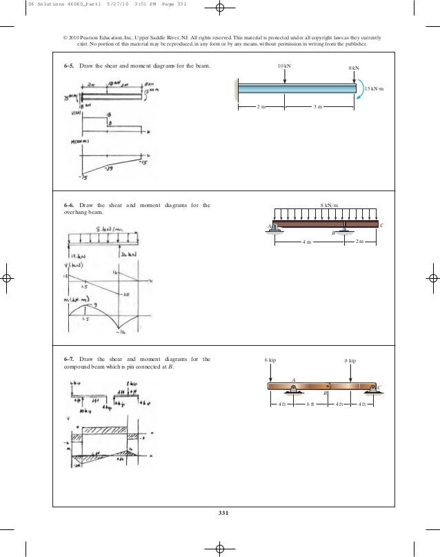
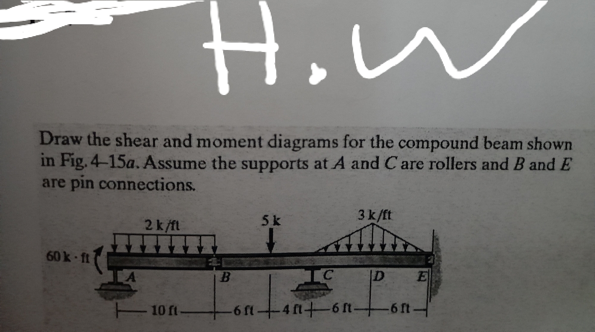
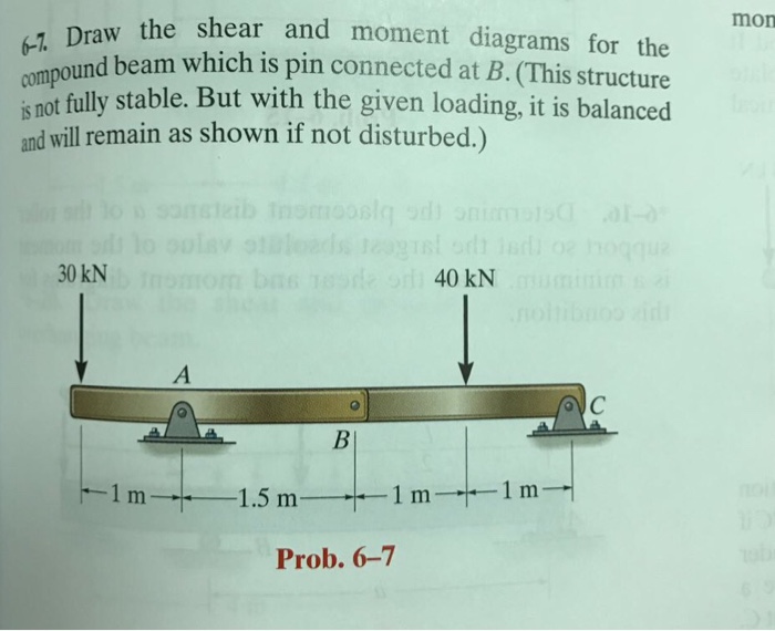
38 draw the shear diagram for the compound beam which is pin connected at b.
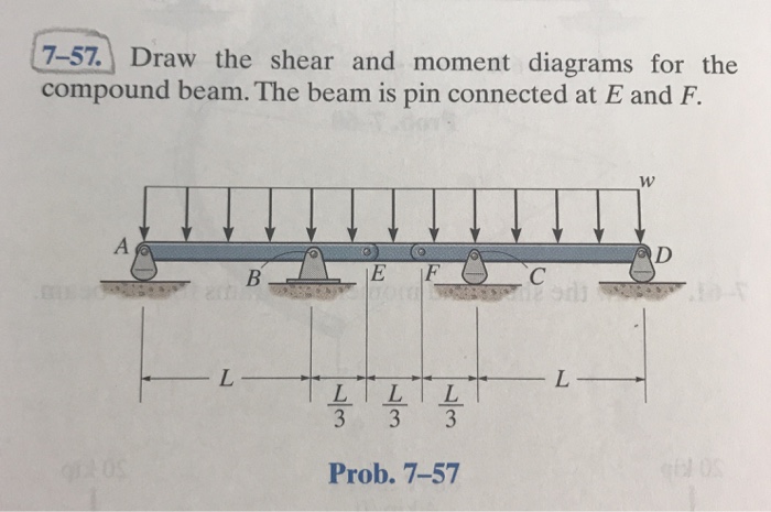
May 28, 2018 · Draw the shear and moment diagrams for the compound beam. The beam is pin-connected at E and F. ... The free-body diagram of the beam’s segment sectioned through the arbitrary points within these two regions are shown in Figs. b and c. Region , Fig. b (1) a (2) Region , Fig. c (3) a (4) The shear diagram shown in Fig. d is plotted using Eqs ... Dec 04, 2015 · 276 MECHANICS OF SOLIDSThe pin resist the force P at the two cross-sections at junction of two bars.∴ Shear stress in pin = P 2 × Area of pin 11471.3 = 18.26 N/mm2 = 2 × π/4 × 202Example 8.29. A compound bar is made of a steel plate 50 mm wide and 10 mm thick to whichcopper plates of size 40 mm wide and 5 mm thick are connected rigidly on ...
Answer to: Draw the shear and moment diagrams for the compound beam which is pin connected at B. (this structure is not sully stable. But with the...1 answer · Top answer: Given data • The value of two downward forces are: 30kN30kN and 40kN40kN Consider all the downward forces with negative...

Draw the shear diagram for the compound beam which is pin connected at b.
The shear force diagram is shown in Figure 2.25. Illustration – 2.4: The objective is to draw the bending moment and shear force diagram for the beam shown in Figure 2.26. The beam in the example is simply supported at both ends. We will start by computing the reactions at the support. For this, use the equilibrium equation Σ M A = 0: A drift bolt (or drift pin) is a long pin of iron or steel, with or without head or point. It is driven into a bored hole through one timber and into an adjacent one, to prevent the separation of the timbers connected and to transmit lateral load. by Pete Silver Will McLean Peter Evans. Enter the email address you signed up with and we'll email you a reset link.
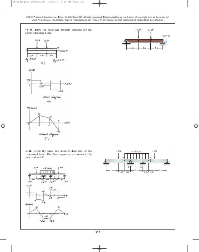
Draw the shear diagram for the compound beam which is pin connected at b.. Draw the shear and moment diagrams for the compound beam which is pin connected at B. (This structure is not fully stable. But with the given loading, ... Draw the shear and moment diagrams for the compound beam. The beam is pin connected at E and F. · Vmax=0.611wL at support C Vmin=−0.611wL at support BMmax=− ...Sep 4, 2020 1、Draw the shear and moment diagrams for the overhang beam. 2、Draw the shear and moment diagrams for the compound beam which is pin connected at B. 3、Draw the shear and moment diagrams for the beam. 4、A member having the dimensions shown is used to resist an internal bending moment of M = 90 kN·m. 1 Answer to Draw the shear and moment diagrams for compound beam. The beam is pin-connected at E andF.1 answer · Top answer: Answer is given below attachment
Question: Draw the shear and moment diagrams for the compound beam which ispin-connected at B. This problem has been solved! See the answerSee the answer ... 21.11.2021. Mechanical testing of a device for subcutaneous internal anterior (Solution) Draw the influence line diagram for (a) the Moment at C,(b) the Shear just to the right of , and (c) the vertical reaction at B. Solve this problem using the basic method. Assume A is a pin, and B is a roller. [ Prob 6-13. chapter – 6, Structural Analysis by R C Hibbeler] Problem 6-15. A pre–stressed concrete beam of cross–sectional area A, moment of inertia ‘I’,distance of top extreme fibre from neutral axis ‘y t ’, and distance of bottom extreme fibre from neutral axis ‘y b ’; is subjected to pre—stressing force such that stress at top fibre is zero. What is the value of eccentricity (r …
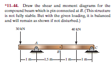
Academia.edu is a platform for academics to share research papers. Solution for *11-44. Draw the shear and moment diagrams for the compound beam which is pin connected at B. (This structure is not fully stable. 6–7. Draw the shear and moment diagrams for the compound beam which is pin connected at B. 4 ft. 6 kip. 8 kip. A. C. B. 6 ft.143 pages Determine the reactions at the supports a and b of the frame. Also, joint B is a hinge. R = force from support (N, lb f) In addition for a beam in balance the algebraic sum of moments equals zero. F2-10. La/( Ib'O. Free-Body Diagram: (Th/te-force body) Reaction at C must pass through E, where the reaction at D and the 150-1b load intersect.
Oct 20, 2017 · P2.66 2.64 The rigid beam of negligible weight is supported by a pin at O and two ver- tical rods. Find the vertical displacement of the 50-kip weight. 2.65 The rigid bar of negligible weight is pinned at O and attached to two vertical rods.
by Pete Silver Will McLean Peter Evans. Enter the email address you signed up with and we'll email you a reset link.
A drift bolt (or drift pin) is a long pin of iron or steel, with or without head or point. It is driven into a bored hole through one timber and into an adjacent one, to prevent the separation of the timbers connected and to transmit lateral load.

Draw The Shear And Moment Diagrams For The Compound Beam Which Is Pin Connected At B This Structure Is Not Fully Stable But With The Given Loading It Is Balanced And Will
The shear force diagram is shown in Figure 2.25. Illustration – 2.4: The objective is to draw the bending moment and shear force diagram for the beam shown in Figure 2.26. The beam in the example is simply supported at both ends. We will start by computing the reactions at the support. For this, use the equilibrium equation Σ M A = 0:

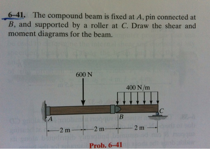
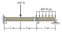
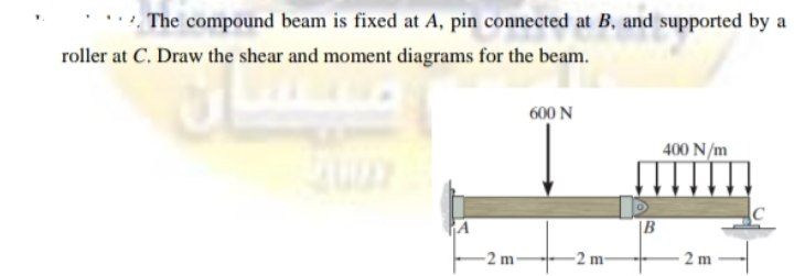
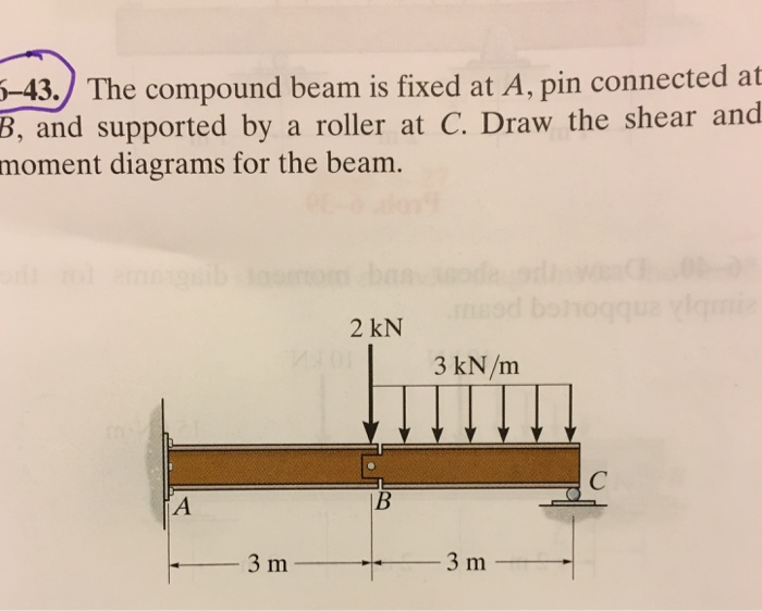
The Compound Beam Is Fixed At A Pin Connected At B And Supported By A Roller At C Draw The Shear And Moment Diagrams For The Beam Holooly Com
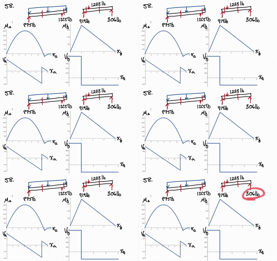
Solved Draw The Shear And Moment Diagrams For The Compound Beam The Beam Is Pin Connected At E And F
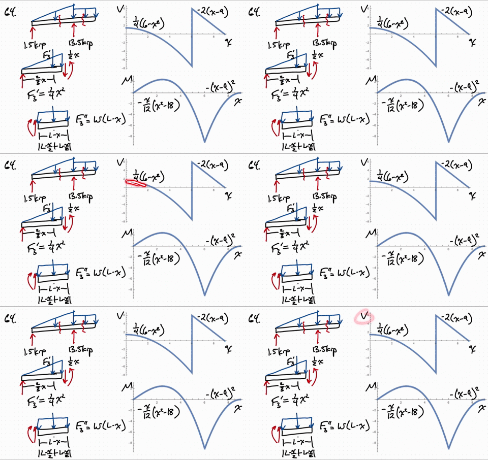
Solved Draw The Shear And Moment Diagrams For The Compound Beam The Beam Is Pin Connected At E And F
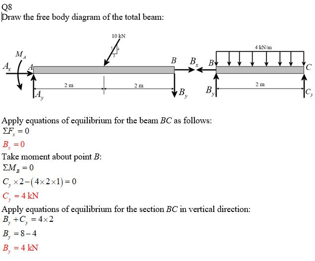
Determine The Horizontal And Vertical Components Of Force Which The Pin At C Exerts On Member Bc Of The Frame In Fig 6 26a The Compound Beam Shown In Fig 6 27a Is Pin

Draw The Shear And Moment Diagrams For The Compound Beam Which Is Pin Connected At B This Structure Is Not Sully Stable But With The Given Loading It Is Balanced And Will

Draw The Shear And Moment Diagrams For The Compound Beam Which Is Pin Connected At B This Structure Is Not Sully Stable But With The Given Loading It Is Balanced And Will

Draw The Shear And Moment Diagrams For The Compound Beam Which Is Pin Connected At B This Structure Is Not Fully Stable But With The Given Loading It Is Balanced And Will

The Compound Beam Is Fixed At A Pin Connected At B And Supported By A Roller At C Draw The Shear And Moment Diagrams For The Beam Holooly Com








0 Response to "38 draw the shear diagram for the compound beam which is pin connected at b."
Post a Comment