37 torque diagram for shaft
From this maximum operating torque, we can find the shaft diameter with the above equation. 2070.06 x 10 3 N-mm = (70Mpa (N-mm 2) x π x d 3 )16. d 3 = 150687.075 mm. d = 53.19 mm. The required shaft diameter will be a 53 mm shaft. Here is an online calculator that Helps you Calculate the shaft diameter. Try it, it will be fun. When a shaft is subjected to a torque or twisting a shearing stress is produced in the shaft. The shear stress varies from zero in the axis to a maximum at the outside surface of the shaft. The shear stress in a solid circular shaft in a given position can be expressed as: τ = T r / J (1) where. τ = shear stress (Pa, lbf/ft2 (psf))
TimeStamp !1:22 - Theory Ends - Solution Beings 3:21 - Step Two - Repeat the process for BC, CD and DE4:47 - Step Three - Draw a Torque Diagram 6:35 - Final ...

Torque diagram for shaft
One of the most common examples of torsion in engineering design is the power generated by transmission shafts. We can quickly understand how twist generates power just by doing a simple dimensional analysis.Power is measured in the unit of Watts [W], and 1 W = 1 N m s-1.At the outset of this section, we noted that torque was a twisting couple, which means that it has units of force times ... The conventional wisdom on torque consists of two major tenets: 1) Players who tend to hook the ball will benefit from a lower torque shaft. Players who tend to slice the ball will benefit from a higher torque shaft. 2) Players who swing faster need lower torque. This assumption is built right into most shafts by the manufacturers: take ... T = torque - or moment (lb in) P hp = horsepower (hp) n = revolution per minute (rpm) 1 hp (English horse power) = 745.7 W; 1 lb in = 0.113 Nm; Electrical motors - Power vs. Torque; Example - Car Engine Torque vs. Power and RPM. A car combustion engine deliveres 100 hp at 5000 rpm to the shaft. The torque in the shaft can be calculated as
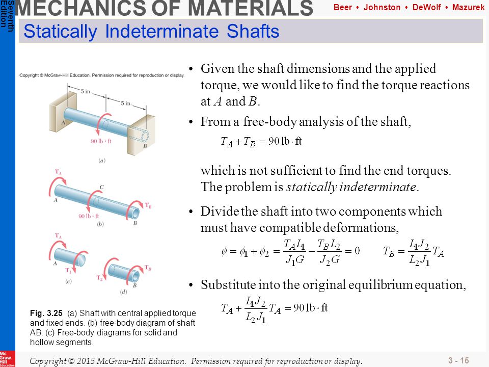
Torque diagram for shaft. For a shaft that is support like a cantilevered beam the moment will be at its greatest where the beam is supported. For a shaft that is supported on both ends you will need to create a moment diagram to find out where the greatest moment is. You will also want to focus on areas where torque in present. 468. 1. Homework Statement: Draw a FBD, determine the largest torque, T1, and find shear stresses in CD and DE. Relevant Equations: Method of sections, static equilibrium. shear stress=Tc/J. I wish to draw a proper free-body diagram for this shaft. However, my FBD does not agree with the solutions manual. torque diagram for the shaft. Apply the force method. Concepts involved: Statically indeterminate structures Force method of analysis In this method the problems are reduced to statical determinancy by removing one of the redundant reactions and calculating the rotation θo at the released support. The required TORQUE ON THE SHAFT: Data given earlier: P = 65 HP n= 2750 rpm Overall torque on the shaft = Torque at Gear 2 = Torque at Gear 3 = Torque at Gear 4 = .˘ ˇ ˆ ˙˝˛˚˜ The torque diagram show the torque applied at all parts of the shaft line . At points 7, 8 and 9 the max torque of 1489 lb ! ˇ ˝˛˚˜. ˜ "#$
problem is to calculate the internal torque in the shaft given the external loadings. Once we have plotted the torsion diagram, it is then easy to read off the maximum internal torque experienced by the shaft. 1) Equilibrium for equating forces and moments on free body diagrams, Part II: Stresses Induced by Torsion Hide Text Produce a torque diagram. Locate the section(s) on the shaft where the combined internal loading is the highest..This important stage requires significant effort and judgement; Assess the strength of the shaft and determine if the safety margin is sufficient. Draw the torque diagram fot the shaft shown below. If the tubular shaft is made from material having an allowable shear stress of {eq}\tau_{allow} {/eq} = 85 MPa, determine the minimum wall ... Transcribed image text: Task 5 Draw a torque distribution diagram for the shaft shown below the shaft is rigidiy fixed at A and is , supported by a bearing of negligible friction at B 300 300 300 7400N 300N 9300 -350 G 300 N 400 và 2 If the shaft in in the above problem is 15mm diameter and made of mild steel determine • The maximum shear stress • A The angle of twist of relative to A and ...
The torque diagram will plot out the internal torsional moment within a shaft that is supporting multiple inputs and/or outputs along its length. The most relevant practical scenarios that match this description are shafts within complex gear or pulley driven systems. This line shaft has a single input delivering torques to multiple outputs via ... Torque Diagram and Torsional Stress of Circular Section Torsional or twisting moment is caused by forces whose resultant does not pass through the axis of rotation (called the shear center) of the structural member. Typically, significant torsions are induced in shafts of Angle of twist along a shaft, torque diagram. Often a shaft has a few torque loadings and we want to quantify the total angle of twist:. To do that, we first obtain our torque diagram, which considers the internal torque for each shaft segment:. Using these internal torque values, we calculate the angle of twist for each segment, and sum them up successively with respect to one end of the shaft: on the shaft will be held in position axially and how power transmission from each element to the shaft is to take place. Intermediate Shaft Mott, 2003, Machine Elements in Mechanical Design Procedure con't 6. Determine the magnitude of torque that the shaft sees at all points. • It is recommended that a torque diagram be prepared. 7.
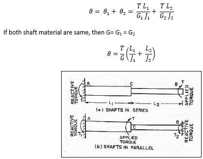
Theory C3 3 Angle Of Twist Solid Mechanics I
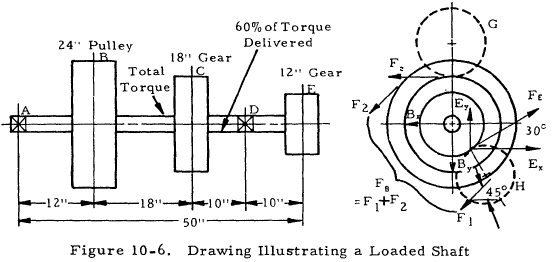
where F 1 is the tension side force and F 2 is the slack side force. The quantity (F 1 - F 2) is the net obtained from the horsepower equation.For flat belts, the value of C is between 2 and 3, depending upon conditions of installation. For V-belts, use C = 1.5.. The axial load produced from gearing must be obtained from considerations of the type of gear-tooth design used.

File Torque Shaft Diagram Gif Wikimedia Commons
Figure 3-2 Diagram of gear's torque transmission calculation. As you can see from Figure 3-2, by reducing the output shaft speed from the input shaft by 1/2, the output torque increases by a factor of 2. 4. Consideration of machine efficiency. As shown in the previous chapter, you can calculate a gear's number of rotations by the number of ...

Axi Symmetric Shafts In Torsion Pdf Document
Torque on Flywheel Shaft. When the driving torque is more than the load torque, the term (T i - T o) is positive and the flywheel is accelerated. When the driving torque is less than the load torque, the term (T i - T o) is negative indicating retardation of flywheel. A T -θ diagram for a particular application is shown in Fig. 2(a).

Synthetic Bending Force Diagram And Torque Diagram Of Shaft D Download Scientific Diagram
In this video, we solve a torque diagram without having to use equations. By simply looking at the external loadings, we can easily draw the internal torque...
Mechanics Map Axial Force Diagrams And Torque Diagrams
The "Torque Sequence" column shows which diagram to use as the specific bolt torquing sequence for your engine . All diagrams can be found in numerical sequence at the back of this publication .

Solved Concentrated Torques On A Steel Shaft Consider The Steel Shaft 1 Answer Transtutors
The torque diagram of a shaft is analogues to the shear force and bending moment diagram of a beam. It is an important engineering diagram from the pulley shaft design point of view. The steps required to draw it will be discussed with the help of the following example:

Synthetic Bending Force Diagram And Torque Diagram Of Shaft B Download Scientific Diagram
T na Tne Torque In the shaft between the gears, 2400 (0.3/2Y 360 N.m Generate shear-moment diagrams for two planes. 360 28 2 422 — 1439 8822 3331 X N N Solution Perform free body diagram analysis to get reaction forces at the bearings. By = 422 N

Gate Ese Shear Stress Induced In A Shaft Subjected To Torsion In Hindi Offered By Unacademy
Now torque 1/4 bolts used on big block to 5-10 ft. lbs. When the stands are in place and tightened down, place the rocker arm and shaft assemblies on the stands and tighten the shaft hold down bolts to 25-28 ft-lbs. After all of the rockers have been tightened down, set valve lash and torque the adjuster screw jam nuts to 15-20 ft-lbs.

Space Diagram Torque Loads And Bending Moment Acting On The Blower Shaft Download Scientific Diagram
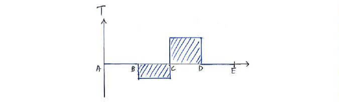
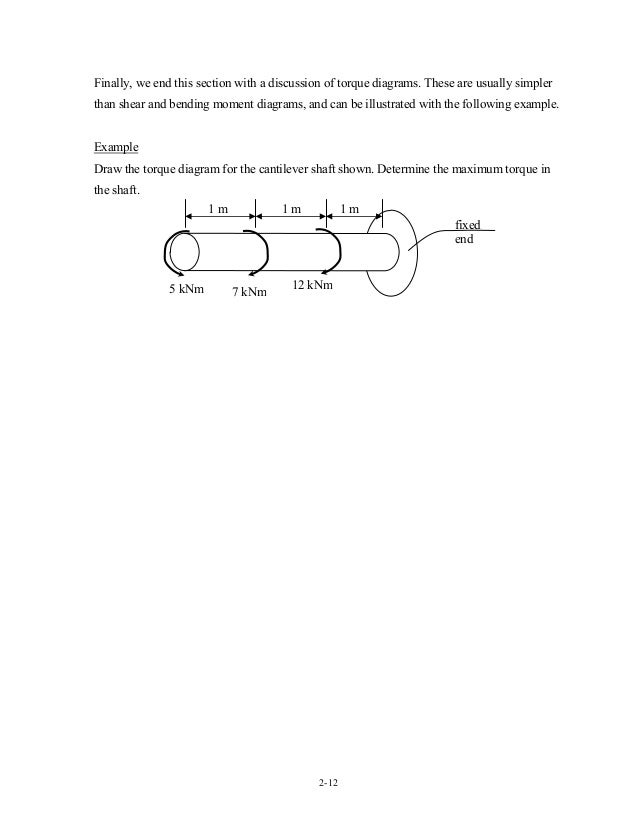
2-12 Finally, we end this section with a discussion of torque diagrams. These are usually simpler than shear and bending moment diagrams, and can be illustrated with the following example. Example Draw the torque diagram for the cantilever shaft shown. Determine the maximum torque in the shaft. 5 kNm 7 kNm 12 kNm 1 m 1 m 1 m fixed end 13. 2-13

Torque Based Bending On Shaft Engineering Stack Exchange
1 August 15, 2007 1 17. Shaft Design Objectives • Compute forces acting on shafts from gears, pulleys, and sprockets. • Find bending moments from gears, pulleys, or sprockets that are transmitting loads to or from other devices. • Determine torque in shafts from gears, pulleys, sprockets, clutches, and couplings. • Compare combined stresses to suitable allowable stresses,
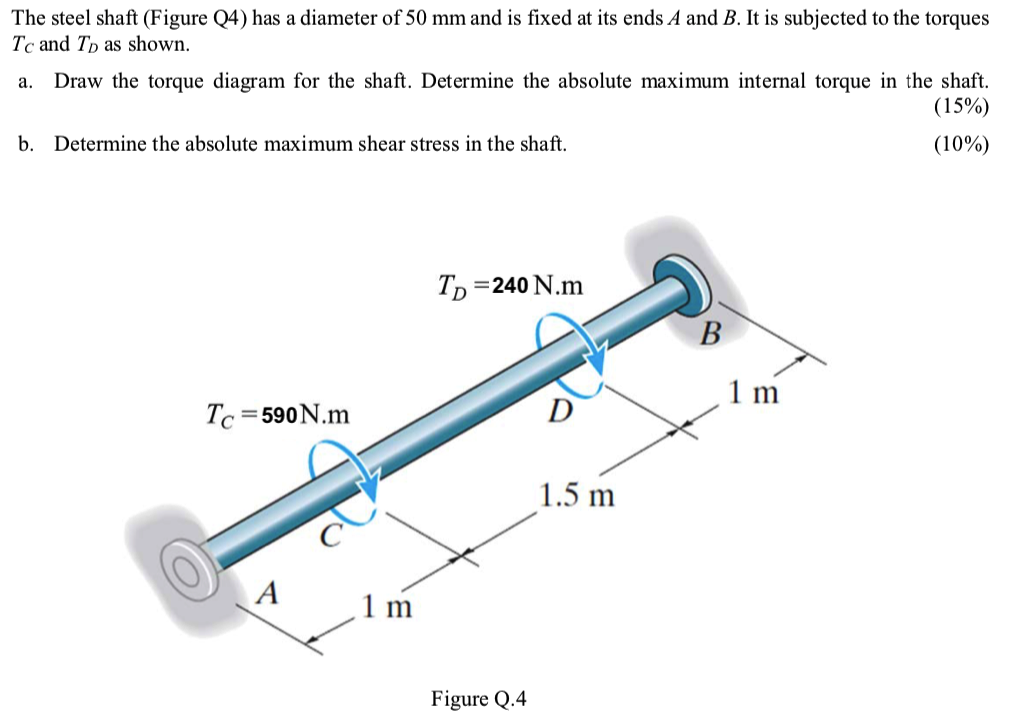
Solved The Steel Shaft Figure Q4 Has A Diameter Of 50 Mm Chegg Com
Draw a free-body diagram of the shaft on either side of the cut Use a static-equilibrium equation and the following sign convention to obtain the internal torque at the section Sign Convention Using the right-hand rule, the torque and angle of twist will be positive, provided the thumb is directed outward from the shaft when the
1
T = torque - or moment (lb in) P hp = horsepower (hp) n = revolution per minute (rpm) 1 hp (English horse power) = 745.7 W; 1 lb in = 0.113 Nm; Electrical motors - Power vs. Torque; Example - Car Engine Torque vs. Power and RPM. A car combustion engine deliveres 100 hp at 5000 rpm to the shaft. The torque in the shaft can be calculated as

Torsion Of Circular Shafts
The conventional wisdom on torque consists of two major tenets: 1) Players who tend to hook the ball will benefit from a lower torque shaft. Players who tend to slice the ball will benefit from a higher torque shaft. 2) Players who swing faster need lower torque. This assumption is built right into most shafts by the manufacturers: take ...
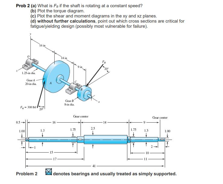
Solved Prob 2 A What Is Fb If The Shaft Is Rotating At A Chegg Com
One of the most common examples of torsion in engineering design is the power generated by transmission shafts. We can quickly understand how twist generates power just by doing a simple dimensional analysis.Power is measured in the unit of Watts [W], and 1 W = 1 N m s-1.At the outset of this section, we noted that torque was a twisting couple, which means that it has units of force times ...

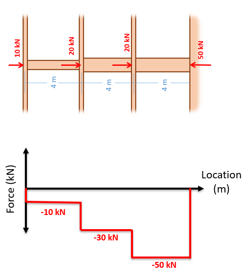
Find Internal Resisting Torque Of Each Segment Of Shaft Under Multiple Torques Make Torque Diagram Youtube

Question 1 10 Marks For The Circular Steel Shaft Subjected To Torque As Shown In Figure 1 Draw The Torque Diagram For The Shaft And Find The Course Hero

Shaft Torsion Problems With Sum 4 And Torque Diagram

Consider The Following Geared Shaft Structure A Draw A Free Body Diagram Of The Entire Shaft Structure B Calculate The Reaction At D C Calculate The Internal Torque Carried By The Shaft
Physics
Torsion Of Shafts
Torsion Of Shafts In Strength Of Materials
Axial Force Shear Force Torque And Bending Moment Diagram

3 Torsion Ppt Download

Synthetic Bending Force Diagram And Torque Diagram Of Shaft C Download Scientific Diagram
3 Torsion Ppt Download
Proper Free Body Diagram For A Shaft Experiencing Multiple Torques Physics Forums

How To Calculate Wheel Torque From Engine Torque X Engineer Org
Shaft Analysis Engineering Library

Torque And Angle Of Rotation In Linked Shafts Geogebra

Mechanical Torsion Meter Principle Inst Tools

Flywheel And Shaft Torque Analysis Engineering Reference And Online Tools

Shear Stress Produced In A Circular Shaft Subjected To Torsion Mechanical Engineering Concepts And Principles

Synthetic Bending Force Diagram And Torque Diagram Of Shaft A Download Scientific Diagram

Structural Mechanics 8
Drive Shafts Roy Mech
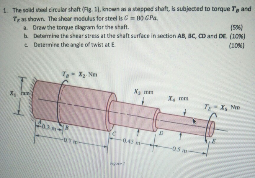
Solved X1 77 X2 62 X3 51 X4 30 X5 33 Chegg Com

Torsion Of Circular Shafts Civil Engineering Portal
0 Response to "37 torque diagram for shaft"
Post a Comment