36 two pipe steam system diagram
Bijan Elahi, in Safety Risk Management for Medical Devices, 2018. 12.7.1.3 Process Flow Diagram. Process Flow Diagrams (PFDs) are a graphical way of describing a process, its constituent tasks, and their sequence. A PFD helps with the brainstorming and communication of the process design. The PFMEA process needs a complete list of tasks that comprise the process under analysis. Jan 2, 2019 — An optimized two-pipe steam system retrofitted with orifice plates, thermostatic radiator valves (TRVs), and properly sized vents provides ...4 pagesMissing: diagram | Must include: diagram
We explain the difference between one pipe and two pipe steam heating systems. ... POST a QUESTION or COMMENT about steam radiator piping, one pipe vs two ...
Two pipe steam system diagram
Fluid Heat Tracing or Steam Tracing and; Electric Tracing; Steam Tracing. In Steam tracing (Fig. 1) of piping, steam is circulated through tubes that run alongside the pipes to keep the process fluid at the desired temperature. Other fluids like organics, glycols, etc … 08/06/2021 · The circulating cooling water performs the extraction of the heat from the steam. Two types of devices are installed on the condenser: the condensate extraction pump and the air extraction pump. ... Schematic diagram of parallel and counter flow steam condensers ... the exhaust steam moves radially inward across the tubes to the suction pipe ... In two-pipe steam installations, steam flows from the boiler to the radiators through an inlet pipe. Once the steam condenses it returns to the boiler ...
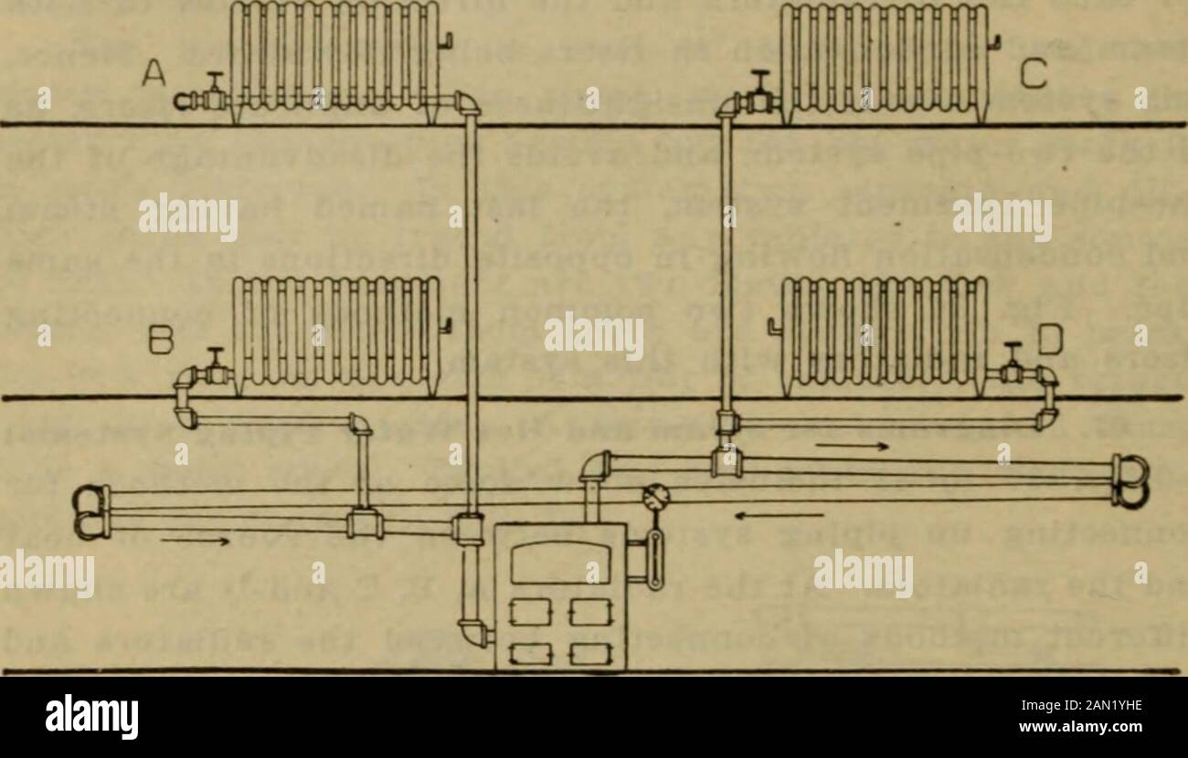
Two pipe steam system diagram. Look at this sketch, here a red & blue arrow shows that mass & energy respectively can transfer to the system and from the system. CS is a control surface that separates control volume from the surrounding. In case of a closed system, we all know that no mass transfer from or to the system but energy transfer can happen. One pipe steam systems allow for condensate and steam to travel throughout the system within the same pipes. As the boiler creates steam it travels through ...8 pages Collects steam at the top of the boiler (well above the water level) so that it can be fed to the engine via the main steam pipe, or dry pipe, and the regulator/throttle valve.: 211–212 : 26 10. Air pump / Air compressor Westinghouse pump (US+) Powered by steam, it compresses air … Fig. 5 is a diagram of a two-pipe system. Here, each radiator has a supply pipe, through which the steam enters, and a return pipe which conducts the water ...
of Steam. A. PUMPED RETURN SYSTEMS. SYSTEM COMPONENTS. TWO-PIPE SYSTEM OPERATION ... This is a schematic of a typical two pipe upfeed system.68 pages Dec 13, 2014 — I've also attached a diagram of a typical 2 pipe steam system. Do you have steam traps on your radiators? Why I'm asking is that while most 2 pipe systems ...90 year-old house, 2-pipe steam, and all kinds of issuesNov 12, 2017Two Pipe Steam - Air Vents and some other confusionOct 19, 2013Two pipe system some cold Radiators - Heating Help: The WallDec 21, 20112-pipe steam heat systemJun 10, 2020More results from forum.heatinghelp.com If a two pipe radiators trap fails closed, it cannot pass the air out of the radiator when the steam pushes against it. The air gets trapped in the radiator and ... There was also a cross connection to this pipe so that steam reaching the engine room from any boiler in the ship could be passed up to the emergency dynamos by opening two or three valves. A schematic of the main and auxiliary steam supply is shown in the diagram below. The Main Reciprocating Engines
heater. The steam and water mixture enters the steam drum through riser tubes, drum internals consisting of demister separate the water droplets from the steam producing dry steam. The saturated water at the bottom of the steam drum flows down through the down comer pipe, normally unheated, to headers and water drum. The easiest way to overcome this problem is by superheating the steam. On the T–s diagram above, state 3 is at a border of the two-phase region of steam and water, so after expansion the steam will be very wet. By superheating, state 3 will move to the right (and up) in the diagram and hence produce a drier steam after expansion. 30/09/2004 · Two Notes: (1) Hilti KB-TZ2 may be directly substituted for TZ in this detail. (2) In the event that SDC C applies and the enclosure(s) in question is “unimportant (i.e., Ip = 1.0 per ASCE 7),” then the enclosure(s) is seismically exempt (per ASCE 7 para. 13.1.4) and only gravity loads need be considered. Piston valves. This type of valve has a hollow piston, (Figure 6.1.12), which is moved up and down by the actuator, covering and correspondingly uncovering the two-ports A and B.Port A and port B have the same overall fluid transit area and, at any time, the cumulative cross-sectional area of both is always equal. For instance, if port A is 30% open, port B is 70% open, and vice versa.
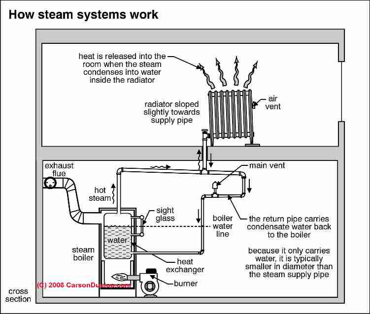
In two-pipe steam installations, steam flows from the boiler to the radiators through an inlet pipe. Once the steam condenses it returns to the boiler ...
08/06/2021 · The circulating cooling water performs the extraction of the heat from the steam. Two types of devices are installed on the condenser: the condensate extraction pump and the air extraction pump. ... Schematic diagram of parallel and counter flow steam condensers ... the exhaust steam moves radially inward across the tubes to the suction pipe ...
Fluid Heat Tracing or Steam Tracing and; Electric Tracing; Steam Tracing. In Steam tracing (Fig. 1) of piping, steam is circulated through tubes that run alongside the pipes to keep the process fluid at the desired temperature. Other fluids like organics, glycols, etc …












0 Response to "36 two pipe steam system diagram"
Post a Comment