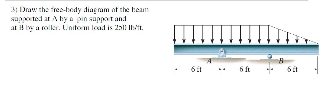
36 draw the free-body diagram for the beam. b is a roller.
A cantilever beam is built into a rigid support at one end, with the other end being free, as shown in Fig.4.1(b). The built-in support prevents displacements as well as rotations of the end of the beam. An overhanging beam, illustrated in Fig.4.1(c), is supported by a pin and a roller support, with one or both ends of the beam Engineering Mechanics - Statics Chapter 5 Solution: Problem 5-3 Draw the free-body diagram of the beam supported at A by a fixed support and at B by a roller. Explain the significance of each force on the diagram. Given: w = 40 lb ft a = 3 ft b = 4 ft θ = 30 deg Solution: A x, A y, MA effect of wall on beam.
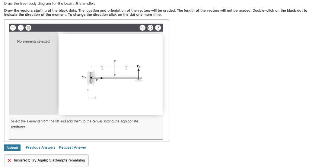
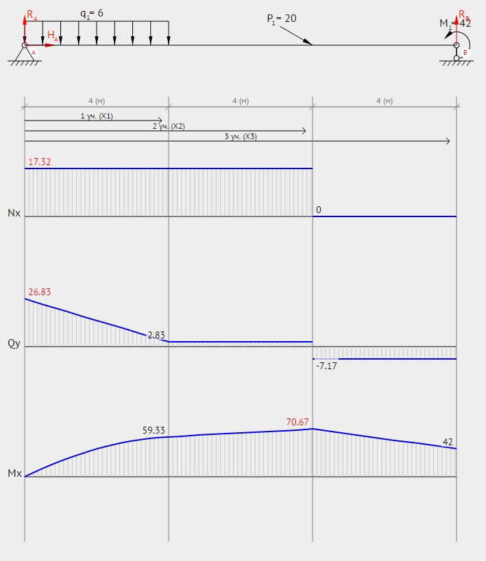
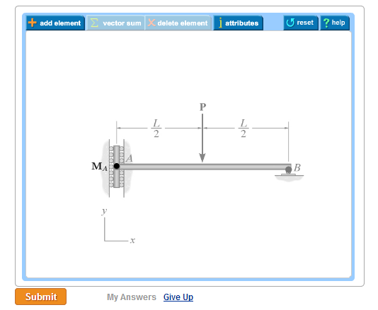
Draw the free-body diagram for the beam B is a roller Draw the vectors starting at the black dots. The location and orientation of the vectors will be graded. The length of the vectors will not be graded. Double-click on the black dot to indicate the direction of the moment.
Draw the free-body diagram for the beam. b is a roller.
F.1 (b), the positive sign convention is (a) tension axial force, (b) shear forces that produce clockwise moments and (c) bending moments that result in tension stresses in the interior frame fibers. The sign convention of F.1(b) can be seen to be equivalent to the beam sign convention rotating columns AB and CD to line up with beam BC. Neglect his weight and friction force between the floor and the man. Part 4. Draw the free-body diagram for the beam. B is a roller. Draw the free-body diagram of the beam supported at A by a fixed support and at B by a roller. Explain the significance of each force on the diagram. Given: w = 40lb/ft. a = 3 ft. b = 4 ft. θ = 30 deg.
Draw the free-body diagram for the beam. b is a roller.. 1. Draw Free Body Diagram 2. Apply Equilibrium Example: Cantilevered Flag Figure M4.3-8 Geometry and free body diagram of cantilevered flag z x ~ ~ ~ • x z m = mass/unit length mg H A V A M A f f L L FREE BODY DIAGRAM: The beam shown in figure below is connected to a pin at point A and rests on a roller at point B. Consider the weight of the beam, draw a free-body diagram ... Examples of drawing free-body diagrams. To better understand how to draw free-body diagrams using the 3 steps, let's go through several examples. Example 1. A box is pushed up an incline with friction which makes an angle of 20 ° with the horizontal. Let's draw the free-body diagram of the box. The first step is to sketch what is happening: 9 Free Body Diagrams Wednesday, October 3, 2012 Equilibrium Expanded ! When we remove that restriction, we can add a second condition for equilibrium M ∑=0 F ∑=0 10 Free Body Diagrams Wednesday, October 3, 2012 Equilibrium Expanded ! The sum of the forces acting on a system must be equal to 0 ! The sum of the moments generated by the
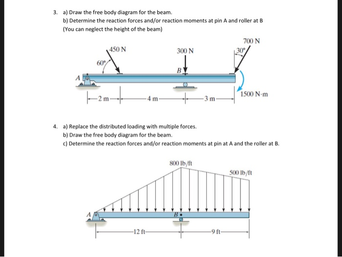
• Create a free-body diagram for the complete frame and solve for the support reactions. • Define a free-body diagram for member BCD. The force exerted by the link DE has a known line of action but unknown magnitude. It is determined by summing moments about C. • With the force on the link DE known, the sum of forces in the x and y directions Draw the shear and moment diagrams for the simply supported beam. Since the loading discontinues at the 9- kN concentrated force, the shear and moment equations must be written for the regions O x < 4 m and 4 m < 6 m Of the beam. The free - body diagrams of the beam's segment sectioned through the arbitrary points in these two regions are shown ... Free Body Diagram and Reactions of a Beam. Given: the beam and loading as shown. Determine: the magnitude of the reactions at A and B after drawing a FBD of the system. Solution: The reactions at A and B are replaced by forces at A and B. The force at B must be vertical because its roller support can only react perpendicular to the surface upon ... Draw the free-body diagram of the uniform . beam. The beam has a mass of 100kg. 5-8 ... Draw the free-body diagram of the beam, which is pin- connected at A and rocker-supported at . B. 5-12 5.3 Equations of Equilibrium ... Free-Body Diagram ...
Roller Support, Hinge Support and Fixed Support. A B F F F Ay By ... 100 N Free Body Diagram. Free Body Diagram. Concrete Wall Machine Weight of floor slab Concrete Beam Free Body Diagram. Actual Structure - A Truss Free Body Diagram. RIGID BODY SYSTEMS ASimple Supported Beam A Cantilever Beam ... Draw the Free Body diagram for the above beam ... Solution for For the beam shown: a. Draw the free-body diagram of the beam. b. Determine the reactions at the supports. Draw the free body diagram (FBD) of (1) the person and (2) the beam AB. Treat B as a roller. mass of the person is 90kg,{eq}\beta=\theta=25^{\circ} {/eq} The structure is made up of beam ABC and the angle bracket BDE. The beam is fixed at point A. The bracket is pinned at point E and is in contact with the beam through a roller at B. We first draw the free-body diagram of the structure as a single unit by removing the supports at A and E and showing the corresponding reactions with assumed senses.
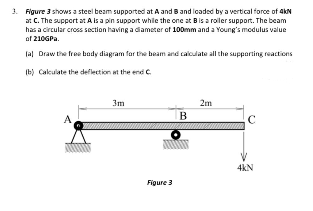
Answered 3 Figure 3 Shows A Steel Beam Bartleby
FREE-BODY DIAGRAMS (Section 5.2) 2. Show all the external forces and couple moments. These typically include: a) applied loads, b) support reactions, and, c) the weight of the body. Idealized model Free-body diagram (FBD) 1. Draw an outlined shape. Imagine the body to be isolated or cut "free" from its constraints and draw its outlined shape.
Solved Draw The Free Body Diagram For The Beam B Is A Chegg Com
Find the reactions at the supports for a simple beam as shown in the diagram. Weight of the beam is negligible. Figure: Concepts involved • Static Equilibrium equations Procedure Step 1: Draw the free body diagram for the beam. Step 2: Apply equilibrium equations In X direction ∑ F X = 0 ⇒ R AX = 0 In Y Direction ∑ FY = 0
Internal Forces And Moments In Beams Springerlink
For the beam loaded as shown in Figure 6.4, A is a pin and B is a roller. a) Draw the free body diagram. (Marks 2) b) Compute the reaction at B. (Marks 2) ...
Solved A Draw The Free Body Diagram For The Beam B Chegg Com
Problem 5.7 The ironing board has supports at A and. B that can be modeled as roller supports. ! WWW. (a) Draw the free-body diagram of the ironing board. (b) ...
Solved Part 1 Draw The Free Body Diagram For The Truss A Chegg Com
Lecture Description. The objectives of this video are to give an introductory overview on how to use free body diagrams to deduce support reactions followed by a comprehensive workout on support reactions example. At first, the video illustrates a given diagram of simply supported beam having a pin support at left end and a roller support at ...
2
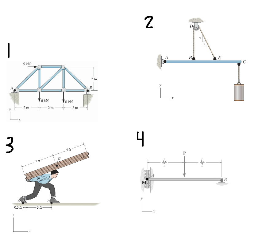
Draw the free-body diagram for the following problems. a) The truss in Prob. $5-15$ b) The beam in Prob. $5-16$ c) The man and load in Prob. $5-17$
Solved A Draw The Free Body Diagram For The Beam B Chegg Com
Free body diagrams may not seem necessary in the relatively simple current applications, but as problems become more complex, their usefulness increases. The following is the process for determining the reaction at the wall for a cantilever beam.

Chapter 4 Equilibrium Equilibrium Means Balance Of Forces To Prevent Body From Translating And Balance Of Moments To Prevent Body From Rotating Vector Ppt Video Online Download
A short video to show how to form an imaginary cut and draw a free body diagram of a simply supported beam with a point load.Related videos:Reactions of a Si...

Draw The Free Body Diagram Of Member Abc Which Is Supported By A Smooth Collar At A Roller At B And Shortlink Cd A Find The Reaction Forces At A B And C
Draw the free body diagram: By taking the moment at B, ΣM B = 0 R Ay × 9 - 20 × 7 - 40 × 4 = 0 9R Ay = 140 + 160 R Ay = 33.3 kN ΣF y = 0 R+ By -20 40 = 0 R By = 20 + 40 -33.3 By = 26.7 kN ΣF x = 0 R Ax = 0 20 kN 40 kN 2 m 3 m 4 m A B R Ay R By R Ax EXAMPLE 1 - Solution

Drawing Shear And Moment Diagrams For Beam Youtube
37 draw the shear diagram for the beam. assume that m0=200lb⋅ft, and l=20ft. Written By Chelsea P. Mariano. Monday, November 15, 2021 Add Comment Edit. Academia.edu is a plat for m for academics to share research papers.

Tutorial 4 Pdf Pdf Applied And Interdisciplinary Physics Materials Science
Jul 28, 2021 ... Draw a free body diagram of box A and box B. Two boxes are stacked on a flat surface: A, weighing 3 pounds, is Figure [Math Processing Error] ...
Hibbeler Chapter5
Draw the beam free body diagram; Replace the uniform distributed load (if any) with the equivalent point load; Solve ΣM A = 0 (sum of moments about support A). This will give you R B (reaction at support B). Solve ΣM B = 0. This will give you R A. Using R A and R B found at steps 3 and 4 check if ΣV = 0 (sum of all vertical forces) is satisfied.

Draw The Free Body Diagram Fbd Of 1 The Person And 2 The Beam Ab Treat B As A Roller Mass Of The Person Is 90kg 25 Study Com
Example 2: For each beam shown, draw the free-body diagram and discuss the support reactions present. Figure a (Move the mouse over the figure to see the free-body diagram.) In Figure a, the beam is supported by a pin or hinge at point A and by a roller at D.
Determining The Shear Force And Bending Moment Equations Of Simply Supported Beam
Draw the free-body diagram of the beam, which is pin connected at Aand rocker-supported at B. SOLUTION. B 5 m. A. 8 m 4 m. ... Equations of Equilibrium:Since the roller at offers no resistance to vertical movement, the vertical component of reaction at support is equal to zero. From the free-body diagram, , , and can be obtained by writing the ...
2
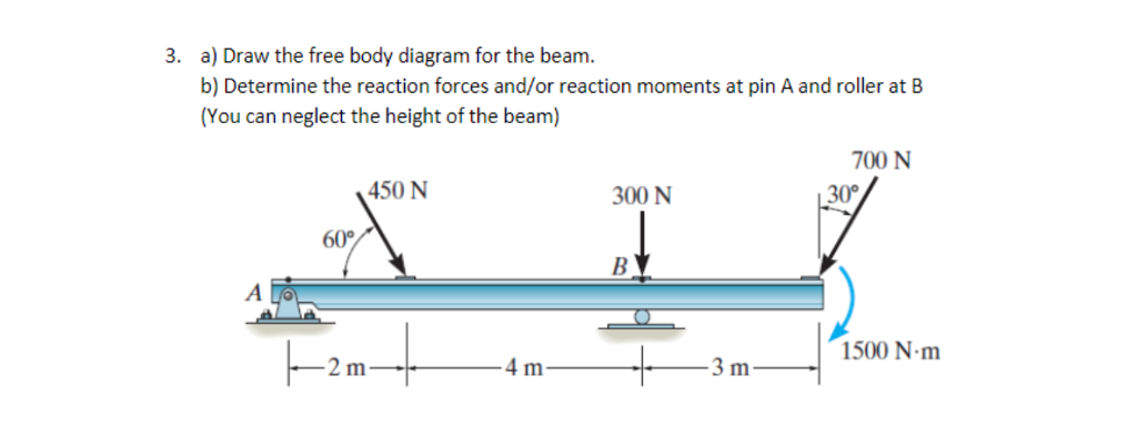
Draw the free-body diagram of the beam supported at A by a fixed support and at B by a roller. Explain the significance of each force on the diagram. Given: w = 40lb/ft. a = 3 ft. b = 4 ft. θ = 30 deg.

Date Draw Free Body Diagram And Write Equilibrium Equation Needed For Determining The Reaction Force At Homeworklib
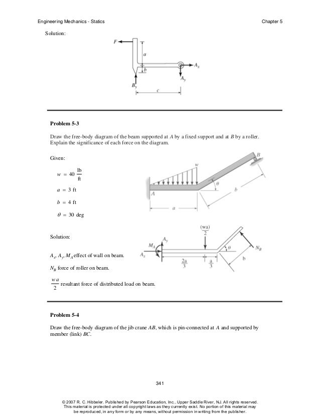
Neglect his weight and friction force between the floor and the man. Part 4. Draw the free-body diagram for the beam. B is a roller.
Solved Please Draw Free Body Diagrams For The Following Chegg Com
F.1 (b), the positive sign convention is (a) tension axial force, (b) shear forces that produce clockwise moments and (c) bending moments that result in tension stresses in the interior frame fibers. The sign convention of F.1(b) can be seen to be equivalent to the beam sign convention rotating columns AB and CD to line up with beam BC.
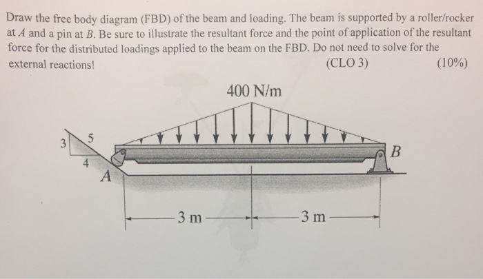
Solved Draw The Free Body Diagram Fbd Of The Beam And Loading The Beam 1 Answer Transtutors
Solved Equilibrium Of A Rigid Body Engineering Mechanics Statics And Dynamics 14th Physics Numerade

The Beam Shown In Figure Below Is Connected To A Pin At Point A And Rests On A Roller At Point B Homeworklib

Roller Support An Overview Sciencedirect Topics
Solved A Draw The Free Body Diagram Of The Beam B Chegg Com
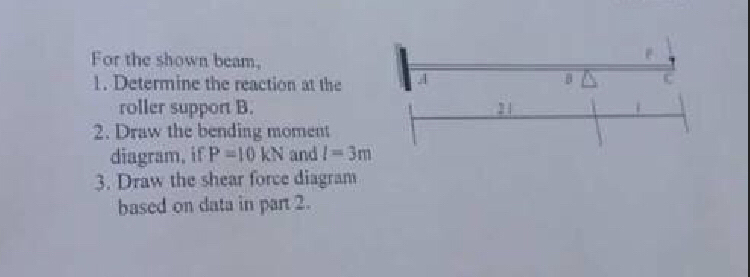
Answered For The Shown Beam 1 Determine The Bartleby

Determine The Reactions At The Roller A And Pin B Youtube

Draw The Free Body Diagram Fbd Of 1 The Person And 2 The Beam Ab Treat B As A Roller Mass Of The Person Is 90kg 25 Study Com

The Compound Beam In The Attachment Is Fixed At A Pin Connected At B And Supported By A Roller At C A Draw The Shear Diagrams For The Beam B Draw The
2
Solved Draw The Free Body Diagram For The Truss A Is A Pin Chegg Com
Beam Reactions And Diagrams Strength Of Materials Supplement For Power Engineering
Example 2
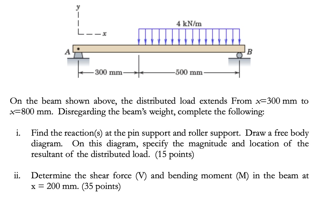
Solved 4 Knim Ct 300 Mm 500 Mm On The Beam Shown Above The Distributed Load Extends From X 3 300 Mm To X 800 Mm Disregarding The Beam S Weight Complete The Following Find

Draw The Shear And Bending Moment Diagrams For Members Ac And Cb Assume Joint A As Homeworklib
2

Problem No 2 For The Beam Loaded As Shown In The Figure Draw The Necessary Free Body Diagram And Calculate The Reactions At A The Roller Support At A B The Internal Reaction

Shear Force And Bending Moment Diagram Practice Problem 1 Youtube

A Draw Fbd To Find The Reaction At A And B And Determine The Reactions B Draw The Shear Force Diagram And Find The Max Shear Force Study Com
0 Response to "36 draw the free-body diagram for the beam. b is a roller."
Post a Comment