36 carnot cycle pv diagram
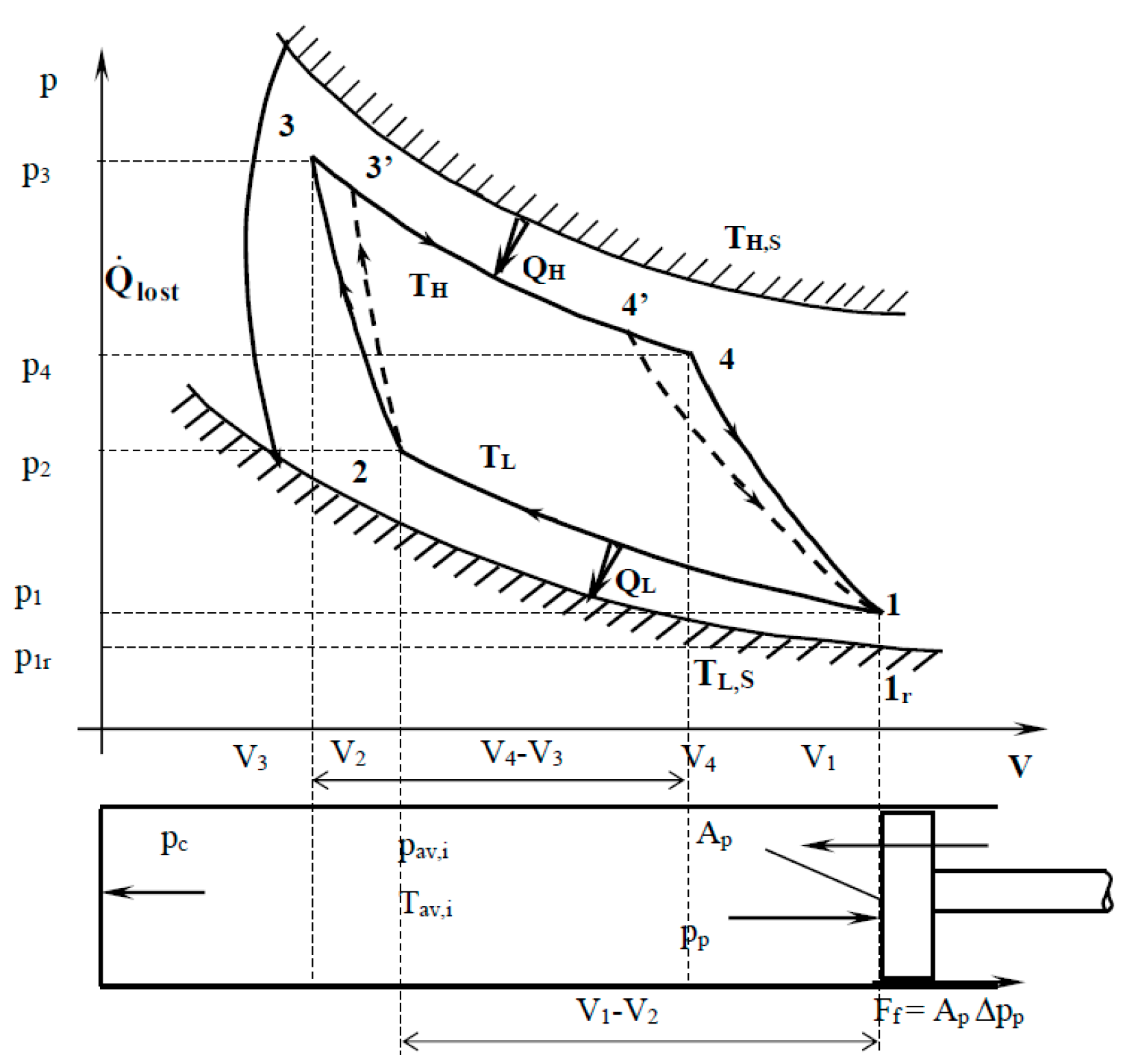
I am tasked to create a PV Diagram of a Carnot Engine Cycle. I must find pressure, volume, Q, W, ΔU, and ΔS on all four points. This is what has been given to me by my teacher: a to b : Isothermal b to c: Adiabatic c to d: Isothermal d to a: Adiabatic T C = 300 K T H = 1700 K p c = 1.01*10 5 Pa v c = 0.01 m 3 Q a to b = 300 K γ (gamma) = 1 ... 12 May 2020 — Process 1-2 Isothermal Expansion · The source (hot body, H.B) at a higher temperature is brought in contact with the bottom B of the cylinder.
The Carnot Cycle is one of the fundamental thermodynamic cycles and is described on this web page. We will use a p-V diagram to plot the various processes in the Carnot Cycle. The cycle begins with a gas, colored yellow on the figure, which is confined in a cylinder, colored blue. The volume of the cylinder is changed by a moving red piston ...

Carnot cycle pv diagram
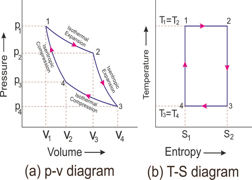
pv and ts diagram of Carnot cycle — That is Carnot's cycle efficiency is fluid independent. Carnot cycle pv diagram | Carnot cycle ts diagram | pv ... What is Carnot Cycle? Air Standard Carnot cycle is ideal cycle consists of four Reversible process. Out of them two are reversible adiabatic & Two are reversible isothermal process. Carnot cycle has maximum efficiency for Engine working between two different temperatures `T_{H}` (heat source temperature) & `T_{L}` (Sink temperature).; For Example:-Heat Engine working between source temperature ... Carnot’s cycle was first developed in the year in 1824 by a French physicist named Sadi Carnot. It is an ideal cycle that basically laid the foundation for the second law of thermodynamics. Carnot cycle also brought up the concept of reversibility. In this lesson, we shall look at all the aspects of Carnot’s cycle as well as understand some ...
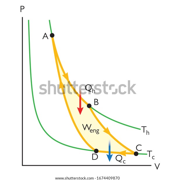
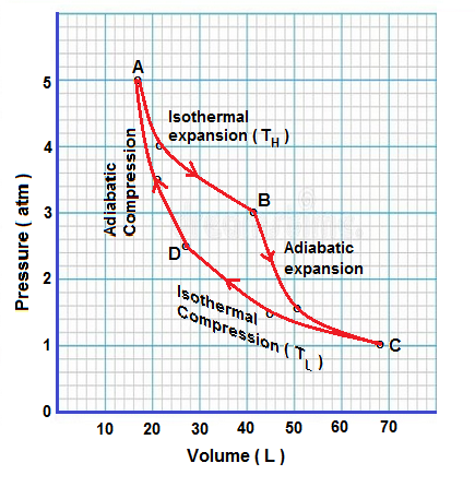
Carnot cycle pv diagram. 5- On a T-s diagram, a vertical line represents an isentropic process (no heat transfer and reversible). The Carnot Cycle. The Carnot cycle is the most ...3 pages When the Carnot cycle is plotted on a pressure–volume diagram (Figure 1), the isothermal stages follow the isotherm lines for the working fluid, the adiabatic ... Thus this entire process in which compression of gas takes place without heat transfer is known as adiabatic compression. This process is shown on the pv diagram as D to A. After this step, the gas returns to its initial stage and this complete cycle is known as Carnot cycle. The energy working on this cycle is called the Carnot engine. The Carnot cycle is often plotted on a pressure- volume diagram (pV diagram) and on a temperature-entropy diagram (Ts diagram). When plotted on a pressure-volume diagram , the isothermal processes follow the isotherm lines for the gas, adiabatic processes move between isotherms and the area bounded by the complete cycle path represents the ...
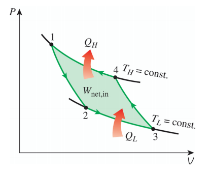
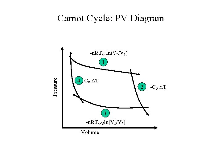
Carnot Cycle Tv Diagram. P-V Diagram for the Carnot engine. 1st law of After completing one cycle: Wtot = W1 + W3 = NkTh Now use rule for adiabats: TVγ-1 = constant. Th VBγ-1= Tc. Learn what PV diagrams are and how to use them to find the change in internal energy, work done, and heat. Proof: Volume ratios in a Carnot cycle. Download scientific diagram | The property diagrams of reversible Carnot cycle. (a) p-v diagram; (b) T-s diagram. from publication: The property diagram in ... The cycle of an ideal gas Carnot refrigerator is represented by the pV diagram of Figure 4.13. It is a Carnot engine operating in reverse. The refrigerator extracts heat Q c Q c from a cold-temperature reservoir at T c T c when the ideal gas expands isothermally. pV diagram of Carnot cycle. The area bounded by the complete cycle path represents the total work that can be done during one cycle. The Carnot cycle is ...
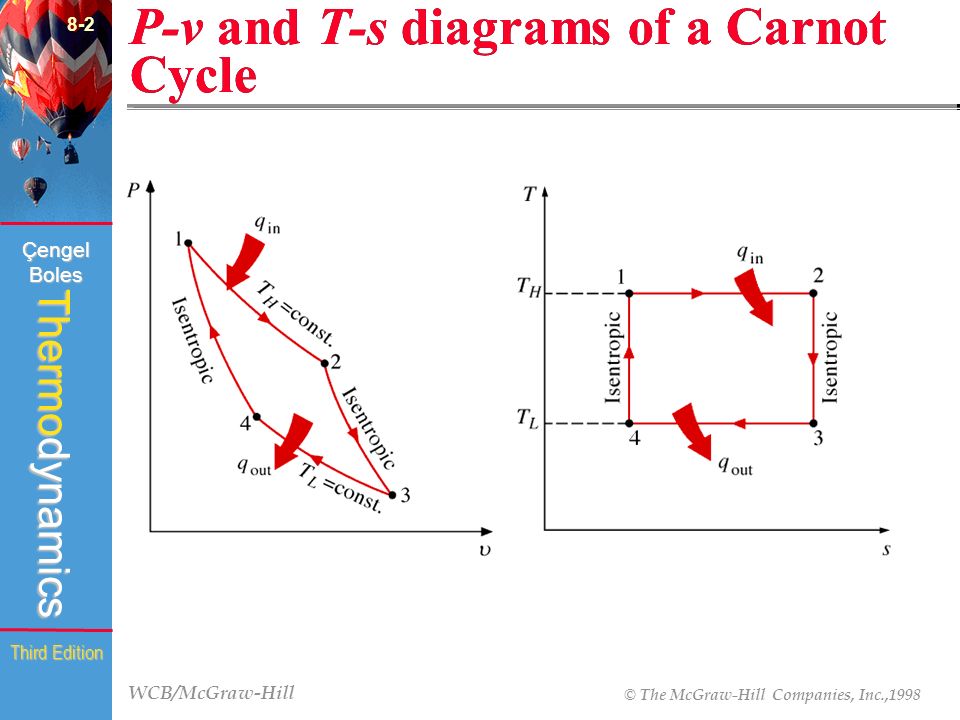
3.5 Carnot cycle: p-V diagram and T-S diagram · A → B: q 1 is isothermally (@ T 1 ) transferred from the first heat reservoir to the system ( w 1 = area ABba) ... The cycle of an ideal gas Carnot refrigerator is represented by the pV diagram of . It is a Carnot engine operating in reverse. The refrigerator extracts heat from a cold-temperature reservoir at when the ideal gas expands isothermally. P-V Diagram — The P-V diagram of the Carnot cycle is shown in Figure 2. In isothermal processes I and III, ∆U=0 because ∆T=0.The Carnot Cycle · P-V Diagram · T-S Diagram · Efficiency Ch 7, Lesson B, Page 14 - Carnot Cycle Represented on a P-V Diagram. On a PV Diagram, the Carnot Cycle looks like a warped parallelogram. The area enclosed by the cycle path is equal to the net boundary work for the cycle. Because the state of the system moves around the cycle path in a clockwise direction, we know that the net work is positive ...

Carnot Vapour Cycle Processes With P V And T S Diagram
Carnot’s cycle was first developed in the year in 1824 by a French physicist named Sadi Carnot. It is an ideal cycle that basically laid the foundation for the second law of thermodynamics. Carnot cycle also brought up the concept of reversibility. In this lesson, we shall look at all the aspects of Carnot’s cycle as well as understand some ...
Thermodynamics The Second Law Of Thermodynamics Introduction To
What is Carnot Cycle? Air Standard Carnot cycle is ideal cycle consists of four Reversible process. Out of them two are reversible adiabatic & Two are reversible isothermal process. Carnot cycle has maximum efficiency for Engine working between two different temperatures `T_{H}` (heat source temperature) & `T_{L}` (Sink temperature).; For Example:-Heat Engine working between source temperature ...
8 Chapter Gas Power Cycles Ppt Video Online Download
pv and ts diagram of Carnot cycle — That is Carnot's cycle efficiency is fluid independent. Carnot cycle pv diagram | Carnot cycle ts diagram | pv ...

Carnot Cycle

P V Diagram Of The Carnot Cycle

The Carnot Cycle University Physics Openstax Cnx

Explain Carnot S Cycle For Heat Engine With P V Diagram Brainly In

Difference Between Carnot Cycle And Rankine Cycle Mech4study
Solved Air In A Piston Cylinder Device Executes A Reverse Chegg Com
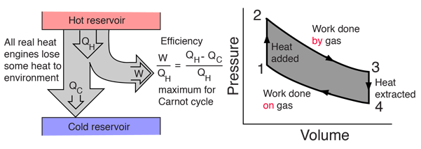
Heat Engines

Carnot Cycle Processes Efficiency Faqs Problems Theorem
Entropy Free Full Text Optimization Modeling Of Irreversible Carnot Engine From The Perspective Of Combining Finite Speed And Finite Time Analysis Html

File Carnot Cycle P V Diagram Svg Wikipedia
Carnot Cycle State 1 Thot Q0 Wcv T

Stirling Cycle Pv And Ts Diagram Mechanical Engineering Concepts And Principles
Carnot Vapour Cycle Processes With P V And T S Diagram

Carnot Cycle Working Principle Processes With Pv Ts Diagram
Pv Diagram Carnot Cycle Thermodynamics Stock Vector Royalty Free 1674409870
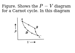
Figure Shows The P V Diagram For A Carnot Cycle In This Diagram Img Src Https D10lpgp6xz60nq Cloudfront Net Physics Images Bms V06 C02 E01 223 Q01 Png Width 80

Carnot Heat Engine

Carnot Refrigeration Cycle Refrigeration Cycle Assignment Help
Show Four Steps Of Carnot Engine In P V Graph Write The Equation Of Each Step And Obtain The Work Done By The System Also Obtain The Efficiency Of A C

Carnot Cycle

What Is Carnot Cycle And Carnot Engine Extrudesign
Carnot Cycle

Carnot Cycle An Overview Sciencedirect Topics
4 Stages Of Carnot Cycle Improving Thermal Efficiency Mechanicaltutorial

Pv Diagram Carnot Cycle Thermodynamics Stock Vector Royalty Free 1674409870

The Property Diagrams Of Reversible Carnot Cycle A P V Diagram B Download Scientific Diagram
Air In A Piston Cylinder Goes Through A Carnot Cycle With The P V Diagram The High And Low Temperatures Are 600 K And 300 K Sarthaks Econnect Largest Online Education Community

File Carnot Cycle Pv Png Wikimedia Commons

Carnot Air Standard Cycle P V And T S Diagram Youtube

Represent Carnot Cycle On P V And T S Diagram Mechanical Engg Diploma Simple Notes Solved Papers And Videos
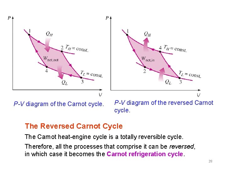
Carnot Cycle Pv Diagram 35 Images Ppt Reversed Carnot Cycle Carnot Cycle
1

File Carnot Cycle T S Diagram Svg Wikimedia Commons
0 Response to "36 carnot cycle pv diagram"
Post a Comment