35 10si alternator wiring diagram
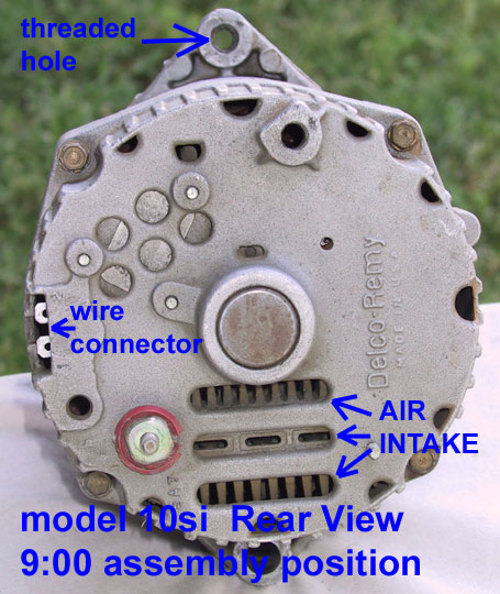
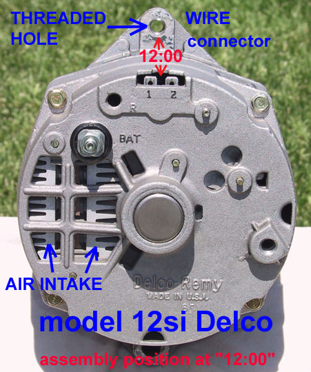
10Si and 12Si Series Alternator for Tractor or Antique Vehicle Conversion. 100% NEW, NO CORE CHARGE. Want HIGH AMP POWER from your Alternator but don't want to install an upgrade kit; we have the answer with our Complete 100% new Alternators. Each alternator is assembled with care using only Top Quality Brand New Components, except stator and rotor may be rewound, and upgraded to the higher ... Oct 10, 2018 · Also, Figure 5-Typical SI wiring diagram showing internal circuits. these alternators have a built-in voltage regulator The model 10SI Delco built alternator is the first generation, SI series alternator. .. position would put the two wire harness connector in direct interference with the “main mounting bolt ,”.
Sep 28, 2018 · Delco Remy 10si Wiring Diagram. HOUSING AND COLLAR INSTALLATION IN 10SI 11SI ALTERNATOR DELCO REMY 10SI, 11SI, 12SI OR BOSCH K1 ALTERNATORS WITH 11SI. 10SI and 12SI are Delco Remy model number designations, but not part numbers. assembly positions provides for proper exit of the wiring from the alternator.

10si alternator wiring diagram
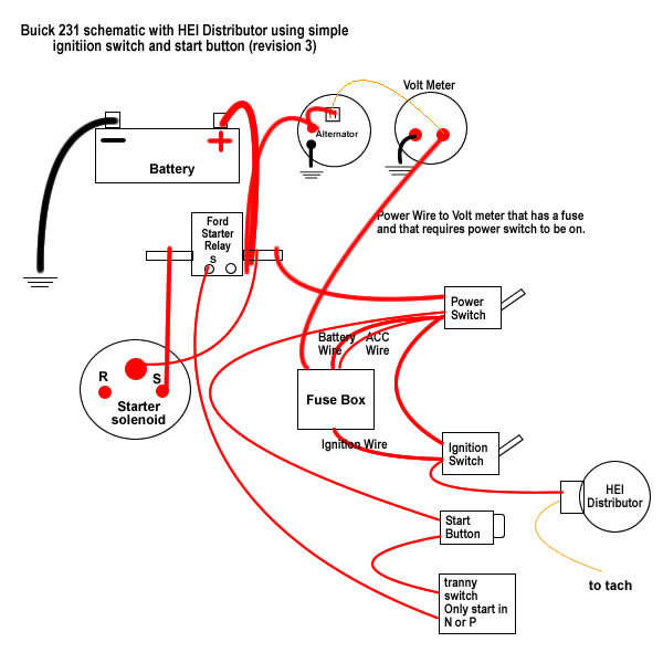
I read all of the posts and found the proper wiring diagrams for a 3 wire 10si. I installed a new alternator (3 wire internal regulator) in my '62 comet. I wired the main lug on the alternator directly to the battery cable side of the ford starter solenoid. I jumped post 2 from the 2 post connector to the main lug on the alternator. Delco 10Si Alternator Wiring Diagram Collection. A wiring diagram is a schematic type that uses abstract illustrated symbols to show all of the components of a system. Wiring diagrams are made up of two things: symbols that represent the components of a circuit, and lines that represent the connections between them. The 12-SI alternator housings are basically the same size as the common 10-SI housing. The Delco CS-series alternators replaced the 12-SI series alternators. These look completely different and generally come with a serpentine belt pulley. The wiring for the charging system is completely different and a bit more complicated than the SI series ...
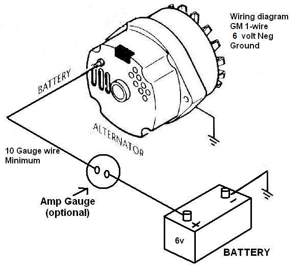
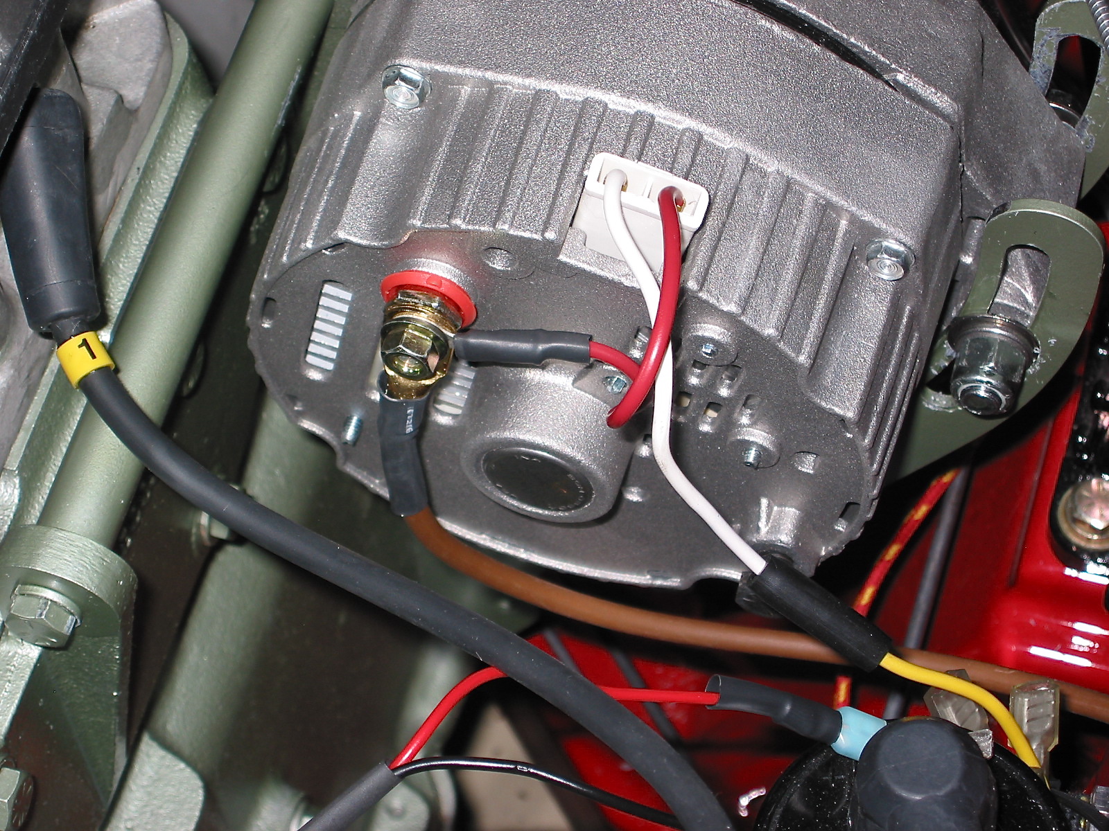
10si alternator wiring diagram. Looking at the diagram for the old alternator, there is a brown wire that goes from the regulator and over to the ACC on the IGN switch. I was thinking that was for switched power. Now, looking at the new harness there is a brown wire, shown in the photo, that is going from the 10SI alternator and I followed it through the harness to the dash ... Sep 22, 2016 · Common Delco SI Series Alternator Wiring Diagram. by David Smith Sep 22, 2016. We are commonly asked how to wire the Delco SI series alternators upon maintenance or upgrading from an older generator. While this series of unit often runs as a self exciting one wire, agricultural applications also used 3 wire connections to the alternator. The Delco® 10-SI is often referred to as the "TWO WIRE" alternator. This is because many successful conversions only connect two wires from the vehicle wiring system to the alternator. There are really four connections on the back of the (two wire) Delco® 10SI, internally-regulated alternator. 10si, 12si & 15si alternator installation instructions warning!!!!always use proper eye protection when performing any mechanical repairs to a vehicle – including, but not limited to, any installation and or repairs to the delco remy alternators. failure to
The original 1960's GM alternator employs an external voltage regulator. This alternator (10-DN), uses a flat, two-prong connection at the back of the alternator. The other main connection on the alternator is the output terminal that charges the battery. The least expensive upgrade from the 10-DN would be to step up to a 10-SI or 12-SI. So I have seen diagrams with the two little connectors, where connector 1 is wired to the Ignition switch (which mine is not) and connector 2 (on the right) is wired back to the primary Alternator output. ... 10si one wire marine alternator: Note ignition-proof screen. 3 wire: #16 IP: 69.122.70.64 ... 10si Alternator Wiring Diagram. All of the wiring diagrams I have seen have a wire from + through Hook the #1 alternator terminal to ACC and the tractor coil power to IGN. This diagram shows how to wire a Delco (GM) internally regulated 3-wire alternator. This particular model (10SI, used in the s and early 80s) is the one. PROBLEM: a careful look at the wiring diagram for the 10DN will show you that the F wire goes to terminal 2, NOT terminal 1, and the 2 wire goes to terminal 1, NOT terminal 2 on the alternator! It looked like for the 10DN alternator, the 2-prong plug wires were crossed from what the 10SI would expect.
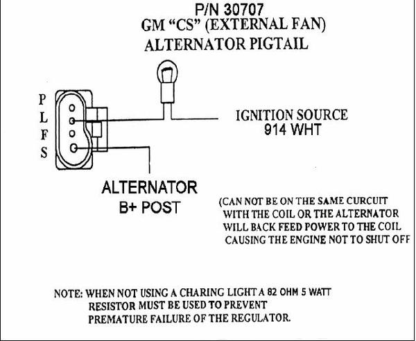
WIRING INSTRUCTIONS GM SI Alternator (One Wire or OE Hookup) Tech Dept. (630) 957-4019 Tech@powermasterperformance.com Replaces these OEM Alternators GM 10DN Externally Regulated GM 10SI Internally Optional Charge Indicator Light Function: Your Powermaster Alternator is designed to work as a 1 wire without any connections to the plug in. The Gm 12si Wiring Diagram. The 12Si Alternator is renown for it's reliability and low RPM high current output. > Complete instructions and straight forward wiring diagram the high quality. This diagram shows how to wire a Delco (GM) internally regulated 3-wire alternator These instructions also apply to the 12SI series, which is similar but can be. Delco Remy Alternator Wiring Diagram - delco remy 10si alternator wiring diagram, delco remy 22si alternator wiring diagram, delco remy 24si alternator wiring diagram, Every electrical arrangement is made up of various distinct pieces. Each part should be set and connected with other parts in particular way. Otherwise, the structure won't work as it ought to be. Figure 5-Typical SI wiring diagram showing internal circuits. (SI and SI Series are identical except stator is a delta.). 10SI Alternator Wiring. The 10SI has three terminals (including those with a 1 wire regulator). The large "BATT" terminal which gets connected to your battery.replacing a 20dn, 30dn, 41 dn, and d.c.

Charging System Wiring For 300 Pump Ford Truck Enthusiasts Forums
10Si Alternator Wiring Diagram Source: rpx-patents.s3.amazonaws.com 10Si Alternator Wiring Diagram Source: alternatorparts.com Read electrical wiring diagrams from bad to positive in addition to redraw the routine being a straight collection.
3 Wire
Jul 23, 2021 - Delco 10si Alternator Wiring Diagram . Delco 10si Alternator Wiring Diagram . Awesome 3 Wire Alternator Wiring Diagram Diagram. Awesome 3 Wire Alternator Wiring Diagram Diagram. Awesome 3 Wire Alternator Wiring Diagram Diagram

3 Wire Alternator Wiring Diagram In 2021 Alternator Electrical Diagram Voltage Regulator
Oct 13, 2018 · A typical 10Si series wiring diagram is illustrated in Figure 3. The basic operating principles are explained as follows. The No. 2 terminal is connected to the battery, and the base-emitter of transistors TR4 and TR1 is connected to the battery through resistor R5, thus turning these transistors on. replacing delco remy 10si, 11si, 12si or bosch k1 alternators with 11si alternator REPLACING S.R.E.

Easy Get Pdf Alternator Wiring Diagram Delco 10si
Delco 10si Alternator Wiring Diagram. and finally we upload it on our website. Many good image inspirations on our internet are the best image selection for Delco 10si Alternator Wiring Diagram. . If you should be pleased with some pictures we provide, please visit us this page again, don't forget to talk about to social networking you have.
Powermaster 150 Wiring Harness Gm 10si Case To Gm 10dn Wiring
Delco 12si Alternator Wiring Diagram Sample. Assortment of delco 12si alternator wiring diagram. A wiring diagram is a simplified conventional photographic representation of an electrical circuit. It reveals the parts of the circuit as simplified shapes, and the power and also signal connections in between the gadgets.
Delco 10si Alternator Issues Hot Rod Forum
Here's a link to my Canadian friends woodsplitter: https://www.youtube.com/watch?v=7yb3eVTTr2I&t=613sThis is not a "how to" video simply because there are an...
My Build Engine And Charging System Connections Ewillys
Actually, this isn't a complex issue at all. (No disrespect to Ron). The issue is wiring a SI alternator, so the regulator is straight-forward and takes queues from it's predecessor, the DN line utilizing external regulation. The queues being actually providing a path from switched power directly into the rotor windings.

One Wire Alternator Page 2 Farmall Cub
Gm Si Alternator Wiring Diagram - wiring diagram is a simplified pleasing pictorial representation of an electrical circuit. It shows the components of the circuit as simplified shapes, and the knack and signal contacts amongst the devices. A wiring diagram usually gives information more or less the relative turn and settlement of devices and ...

Chevy Alternator Wiring Diagram The H A M B
delco 10si alternator wiring diagram - You will want a comprehensive, professional, and easy to comprehend Wiring Diagram. With this sort of an illustrative manual, you'll be able to troubleshoot, avoid, and full your projects easily. Not only will it assist you to attain your required outcomes more quickly, but additionally make the whole ...

Alternator Wiring The 1947 Present Chevrolet Gmc Truck Message Board Network
10Si Series Alternator Introduction10Si Alternator Operating Principles. A typical 10Si series wiring diagram is illustrated in Figure 3. The basic operating principles are explained as follows. The No. 2 terminal is connected to the battery, and the base-emitter of transistors TR4 and TR1 is connected to the battery through resistor R5, thus ...

1949 Cub 12volt Wiring Farmall Cub
Hello. Today I show you how to wire a 10si one wire alternator to a diesel farm tractor. This method makes the alternator start charging as soon as the engin...
Gm 10si 3 Wire Alternator Question The H A M B
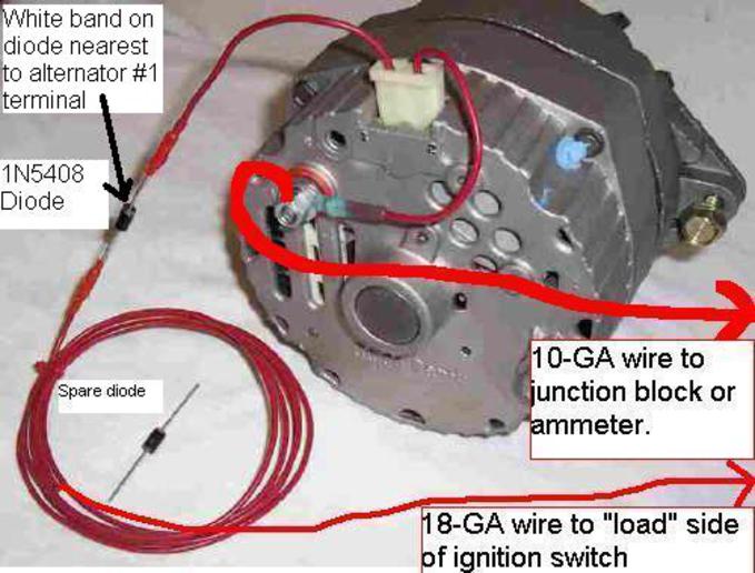
There are many 10si wiring diagrams out there, and the one Doc posted is a very common solution. BAT terminal (threaded post on the back of alternator) - This charge wire should be connected as directly as possible to the battery, using a fusible link for protection. A 10 gauge wire with 14 gauge fusible link will work for 10si's up to 63 amp.
Cape Starter Alternator Diagrams
The 12-SI alternator housings are basically the same size as the common 10-SI housing. The Delco CS-series alternators replaced the 12-SI series alternators. These look completely different and generally come with a serpentine belt pulley. The wiring for the charging system is completely different and a bit more complicated than the SI series ...
Alternator Wiring Moyer Marine Atomic 4 Community Home Of The Afourians
Delco 10Si Alternator Wiring Diagram Collection. A wiring diagram is a schematic type that uses abstract illustrated symbols to show all of the components of a system. Wiring diagrams are made up of two things: symbols that represent the components of a circuit, and lines that represent the connections between them.

Delco Alternator Wiring Diagram Collection Laptrinhx News
I read all of the posts and found the proper wiring diagrams for a 3 wire 10si. I installed a new alternator (3 wire internal regulator) in my '62 comet. I wired the main lug on the alternator directly to the battery cable side of the ford starter solenoid. I jumped post 2 from the 2 post connector to the main lug on the alternator.

Delco 10si Alternator Wiring Diagram In 2021 Diagram Wire Alternator
The Delcotron 10si Alternator Thread Ih Parts America
The Delcotron 10si Alternator Thread Ih Parts America
Assorted Electrical Modifications Valve Chatter

Fuselink To Alternator Jeepforum Com

How To Wire A 1 Wire Alternator 10si Delco Style To A Farm Tractor Youtube

Lucas Alternator Ih Construction Equipment Red Power Magazine Community
Catalog
Gm Single Wire Alternator Wiring Mg Engine Swaps Forum Mg Experience Forums The Mg Experience
Has Anyone Used A 10si 3 Wire Alte Yesterday S Tractors

Wilson Part Details

Typical Alternator Wiring Free Image Diagram
Scool Me In Wiring Page 4 Ih8mud Forum

Gm 10si Alternator Wiring Issues The H A M B Alternator Diagram Delco

Identify Diagram Alternator Wiring Pic2
What Is This Box On The Diagram Gm Square Body 1973 1987 Gm Truck Forum
Wiring A Delco Gm Alternator

2920 01 126 1585 10si Alternator 12v72a Type 116 136 Fits Gm 1105435 1102933 9 O Clock Dp Equipment Llc
10si Alternator Wiring Chevy Nova Forum
Catalog
0 Response to "35 10si alternator wiring diagram"
Post a Comment