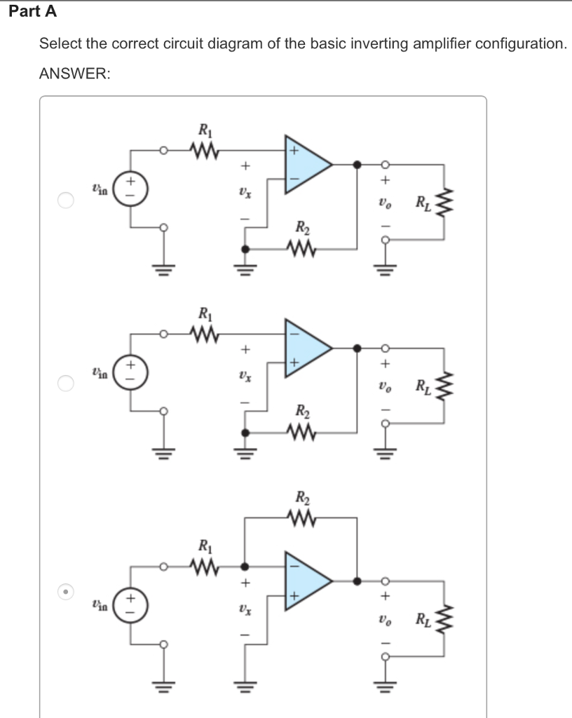
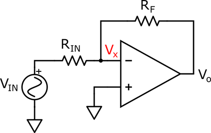
36 select the correct circuit diagram of the basic inverting amplifier configuration.
Cumulative (4) Flashcards - Quizlet The electric field between two parallel plates has a magnitude of 180 N/C. The two plates are 2.5 cm apart. Recall that the magnitude of the charge on an electron is 1.602 × 10⁻¹⁹ C. Inverting Schmitt Trigger | Analog-integrated-circuits ... A part of output is fed back to the non-inverting (positive) input of the op-amp, hence called as positive feedback comparator. The inverting Schmitt trigger is shown below, The triggering point VT is calculated as VT=R2/(R1+R2 ) Vout. If Vout=+Vsat , VT=+ve If Vout=-Vsat , VT= -ve Thus when output is +Vsat, the upper threshold point is given as
Design Amplifier Pdf Audio [JB6ZEL] Search: Audio Amplifier Design Pdf. About Audio Design Pdf Amplifier
Select the correct circuit diagram of the basic inverting amplifier configuration.
(PDF) Lessons In Electric Circuits Volume VI Experiments ... Lessons In Electric Circuits Volume VI Experiments. Christian Bortolas. Download Download PDF. Full PDF Package Download Full PDF Package. This Paper. A short summary of this paper. 8 Full PDFs related to this paper. Read Paper. Download Download PDF. Non-inverting Schmitt Trigger | Analog-integrated-circuits ... In non-inverting Schmitt trigger, the input signal is applied at the non-inverting terminal of op-amp as shown below. In this the voltage present at non-inverting terminal (V+) is compared with the voltage present at inverting terminal (V- = 0V) The operation of the circuit can be explained with the help of two conditions: 1. The Simplest Audio Amplifier Circuit Diagram The amplifier circuit diagram shows a 2.5W * 2 stereo amplifier. You can also make a 5W mono amplifier out of it. (Check out the TEA2025 datasheet for more information on that) On the input side, you should use a dual potentiometer. A dual potmeter allows you to connect both the left and right channels on one potentiometer.
Select the correct circuit diagram of the basic inverting amplifier configuration.. (PDF) GATE SOLVED PAPER -EC ANALOG ... - Academia.edu The ammeter will read (A) 0.4 2 A (B) 0.4 A (C) 0.8 A (D) 0.4 mamp p p Q. 144 The circuit shown in the figure is that of (A) a non-inverting amplifier (B) an inverting amplifier (C) an oscillator (D) a Schmitt trigger 1996 TWO MARKS Q. 145 In the circuit shown in the given figure N is a finite gain amplifier with a gain of k , a very large ... Design Guide for 12V Systems - outbackjoe A comprehensive design guide for 12V systems or dual battery systems used in vehicle setups for touring and camping. This article explains the different solutions to keeping your fridge running and lights on without bias or attempts to sell any dual battery system products. Simple Delay Timer Circuits Explained - Homemade Circuit ... The first circuit diagram shows how a transistors and a few other passive components may be connected for acquiring the intended delay timing outputs. The transistor has been provided with the usual base resistor for the current limiting functions. A LED which is used here just indication purposes behaves like the collector load of the circuit. transistor amplifier circuit diagram using 2sc5200 and ... transistor amplifier circuit diagram using 2sc5200 and 2sa1943. This is PNP and NPN amplifier circuit diagram. We used 2sc5200 and 2sa1943. 2sc5200 is NPN transistor and 2sa1943 is PNP transistor. We can use maximum 230 volt and 1.5 ampere. But here in this circuit diagram we can use maximum 50 voltage. The voltage depends on various circuits.
Diffraction Quiz Flashcards | Quizlet Light with a wavelength of about 510 nm is made to pass through a diffraction grating. The angle formed between the path of the incident light and the diffracted light is 12.0° and forms a first-order bright band. Troubleshooting Electronics - DocShare.tips Electronic components shown on the circuit diagrams are generally in the following units unless mentioned otherwise: Figure 2.8(a) and (b) are based on symbols recommended by the American National Standard Institute: ANSI Standard U 32.2-1970. Fig. 2.8 (a) Schematic circuit symbols (b) Special symbols used on circuit diagrams as per American ... PDF ASSIGNMENT-3 HINTS &SOLUTIONS - Kits W KITSW_ECE_KAR_BEL_A3_SOLUTIONS 2015-16, II SEM Page 3 of 16 v V ti m= sin( )ω is the secondary voltage of the step-down transformer used. Draw the circuit diagram carefully … The circuit diagram of half-wave rectifier is shown below 5 Best 6V 4Ah Automatic Battery Charger Circuits Using ... The above shown circuit configuration was not changed in any manner. The circuit was set to cut off at 13.46V, which was selected as the full charge cut off level. This was done to save time because the actual recommended value of 14.3V could have taken lot of time, therefore to make it quickly I selected 13.46V as the high cut off threshold.
(PDF) Custom Asic for Electroneurographic Recording Using ... The circuit consists of a fully-integrated, ultra low-noise, This document reports the design, fabrication and testing of two generations of custom ASICs designed for the recording of electroneurographic (ENG) activity using nerve cuff electrodes. The circuit consists of a fully-integrated, ultra low-noise, Bridge rectifier - Definition, Construction and Working The construction diagram of a bridge rectifier is shown in the below figure. The bridge rectifier is made up of four diodes namely D 1 , D 2 , D 3 , D 4 and load resistor R L . The four diodes are connected in a closed loop (Bridge) configuration to efficiently convert the Alternating Current (AC) into Direct Current (DC). 2.1 Modeling an Ideal Op Amp with Spice - McGill University The Miller Integrator . Our next example illustrates another important application of the inverting op amp configuration. Consider replacing R 2 in the inverting amplifier circuit shown in Fig. 2.2 with a capacitor C 2.The resulting configuration is known as the inverting or Miller integrator circuit and is shown in Fig. 2.5. CMOS Digital Integrated Circuits Analysis & Design ... A list of all MOSFET model parameters is given in Table 4.1. The equivalent circuit structure of the NMOS LEVEL 1 model, which is the default MOSFET model in SPICE, is shown in Fig. 4.1. This basic structure is also typical for the LEVEL 2 and LEVEL 3 models.
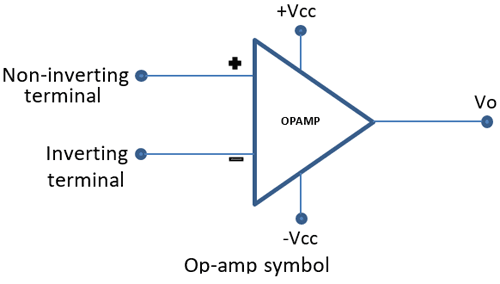
Chapter 4 : Operational Amplifiers
Solved Draw the circuit diagram of the basic inverting ... Question: Draw the circuit diagram of the basic inverting amplifier configuration. Give an expression for the closed-loop voltage gain of the circuit in terms of the resistances, assuming an ideal op amp. Give expressions for the input impedance and output impedance of the circuit.

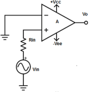
Non-Inverting Operational Amplifier Circuit » Electronics Notes
Electronic Devices and Circuits | Subject Wise - AcademyEra The circuit is used as an amplifier with the input connected between G and S terminals and the output taken between D and S terminals, ... A p-i-n photodiode of responsivity 0.8A/W is connected to the inverting input of an ideal op- amp as shown in the figure, ... Select the correct answer using the code given below. A. 1, 2 and 3 . B.

Low Power Op Amps - Documents - Essentials - element14 Community
PDF assessment id-85 - NPTEL Basic Op-amp Applications and Introduction to Development Kit Basic Op-amp Practical ... Consider a non-inverting Schmitt trigger configuration. If an input of 1 Vp is applied then what will be the output waveform when the 1 point ... The input signal is on the top and the output waveform s at the bottom. Select the 1 point correct circuit ...

Op-amp Tutorial 2 : Features of inverting and non-inverting ...
Design-of-Asynchronous-Sequential-Machine | Finite State ... These equations are then checked to see the presence of static and dynamic hazards, to ensure correct circuit operation. Deriving the Flow Tables : • The state tables are used in design of the synchronous sequential circuits. Similarly flow tables are used to design the asynchronous sequential circuits.

Differential amplifier - Wikipedia
Correct Circuit Diagram - U Wiring Circuit or schematic diagrams consist of symbols representing physical components and lines representing wires or electrical conductors. Ad Templates Tools Symbols For Any Circuit Diagram Or Design. Part A Select the correct circuit diagram of the basic inverting amplifier configuration ANSWER lin vo R R2 lin R2 R2 Ri in to R.
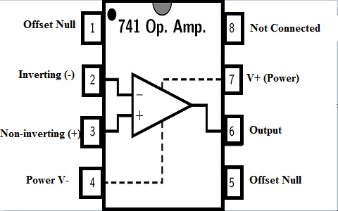
Operational Amplifier Basics, Types and Uses| Article | MPS
(PDF) Op Amps For Everyone | Vitor Otávio - Academia.edu Academia.edu is a platform for academics to share research papers.
Non Inverting Operational Amplifiers Working and Applications
Solved Part A Select the correct circuit diagram of the ... Solved Part A Select the correct circuit diagram of the | Chegg.com. Engineering. Electrical Engineering. Electrical Engineering questions and answers. Part A Select the correct circuit diagram of the basic noninverting amplifier configuration. 2 3 4 Risu w.
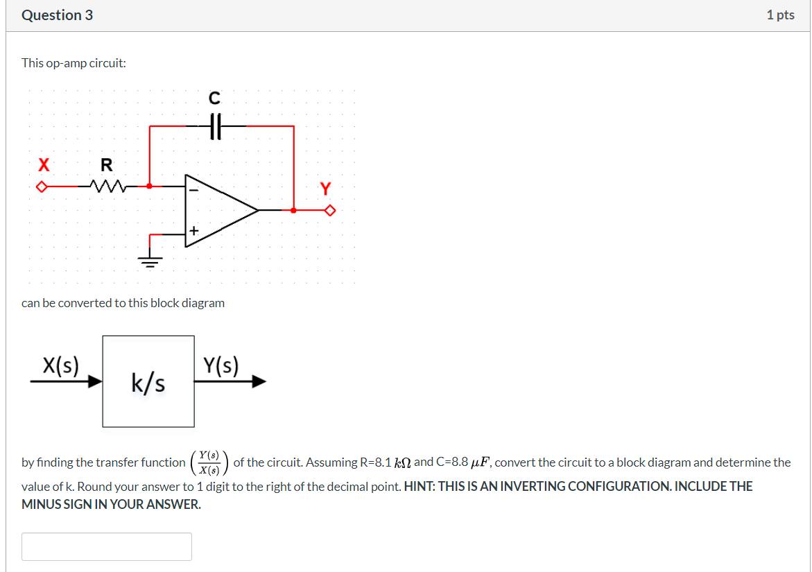
Solved Question 3 1 pts This op-amp circuit: ..... . .R + ...
mesh-analysis | DC circuits - Electronics Tutorial Step 1 :Draw the correct circuit diagram and name all the junctions (nodes), as A, B, C ….. etc. Step 2 :Mark all the possible branch currents or loop currents with some assumed directions. Note that the assumed current may be correct or may be wrong. If an assumed current direction is correct, then in the answer it comes out to be positive.
Non Inverting Operational Amplifiers Working and Applications
Solved Part A Select the correct circuit diagram of the ... Solved Part A Select the correct circuit diagram of the | Chegg.com. Engineering. Electrical Engineering. Electrical Engineering questions and answers. Part A Select the correct circuit diagram of the basic inverting amplifier configuration ANSWER lin vo R R2 lin R2 R2 Ri in to R.

Matching Op Amps to ADCs | DigiKey
108+ Power amplifier circuit diagram with PCB layout ... Top 3 circuits of NE5532 Preamplifier tone control. Top 3 Graphic Equalizers —Low noise, Cheap, and easy. TDA1524 stereo tone control. Low Noise Tone control If you want to avoid noise in the audio system you should try this. It uses NE55532, LF353, and more. Super Bass Booster It is a small circuit diagram with PCB.
Solved Part A Select the correct circuit diagram of the ...
(PDF) Laboratory Manual for Engineering Electronics ... Download Full PDF Package. Translate PDF. GALILEO, University System of Georgia GALILEO Open Learning Materials Engineering Open Textbooks Engineering Summer 2019 Laboratory Manual for Engineering Electronics Sandip Das Kennesaw State University, sdas2@kennesaw.edu Walter Thain Kennesaw State University, wthain@kennesaw.edu Sheila Hill Kennesaw ...
OP-AMP Configurations: Inverting and Non-Inverting
The Simplest Audio Amplifier Circuit Diagram The amplifier circuit diagram shows a 2.5W * 2 stereo amplifier. You can also make a 5W mono amplifier out of it. (Check out the TEA2025 datasheet for more information on that) On the input side, you should use a dual potentiometer. A dual potmeter allows you to connect both the left and right channels on one potentiometer.
![MCQ] Linear Integrated Circuit - Last Moment Tuitions](https://i.ibb.co/m46jFgz/9.png)
MCQ] Linear Integrated Circuit - Last Moment Tuitions
Non-inverting Schmitt Trigger | Analog-integrated-circuits ... In non-inverting Schmitt trigger, the input signal is applied at the non-inverting terminal of op-amp as shown below. In this the voltage present at non-inverting terminal (V+) is compared with the voltage present at inverting terminal (V- = 0V) The operation of the circuit can be explained with the help of two conditions: 1.

Basic Amplifier Configurations: the Inverting Amplifier ...
(PDF) Lessons In Electric Circuits Volume VI Experiments ... Lessons In Electric Circuits Volume VI Experiments. Christian Bortolas. Download Download PDF. Full PDF Package Download Full PDF Package. This Paper. A short summary of this paper. 8 Full PDFs related to this paper. Read Paper. Download Download PDF.

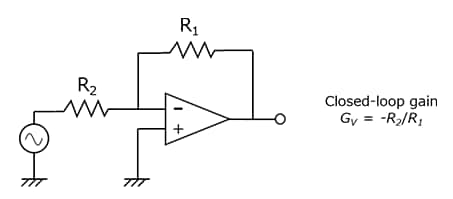
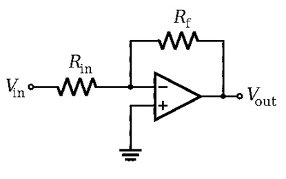
Inverting Operational Amplifier - The Inverting Op-amp

52 questions with answers in OPERATIONAL AMPLIFIERS | Science ...
Why inverting amplifier is used in most cases then non ...

What are the Golden Rules of Op-Amps? | CircuitBread
![MCQ] Linear Integrated Circuit - Last Moment Tuitions](https://i.ibb.co/JpzJC32/1.png)
MCQ] Linear Integrated Circuit - Last Moment Tuitions

Non-inverting op-amp (video) | Amplifiers | Khan Academy
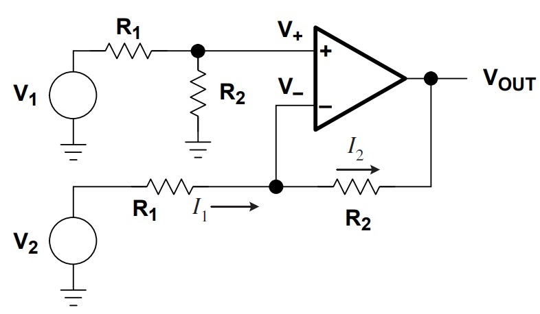
Op Amp Differential Amplifier Circuit | Voltage Subtractor
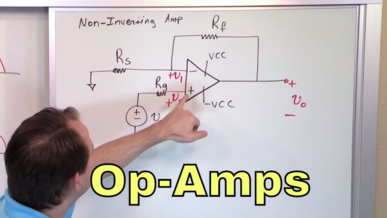
01 - The Non-Inverting Op-Amp (Amplifier) Circuit

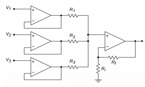
Summing Amplifier is an Op-amp Voltage Adder
Inverting Operational Amplifier (Op-amp): Circuit Design ...
Inverting and Non-inverting Amplifier and Their Differences
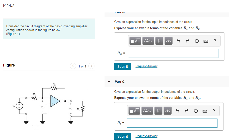
Solved P 14.7 Give an expression for the input impedance of ...
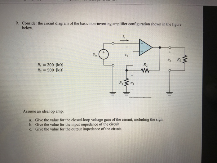
Solved 9. Consider the circuit diagram of the basic | Chegg.com
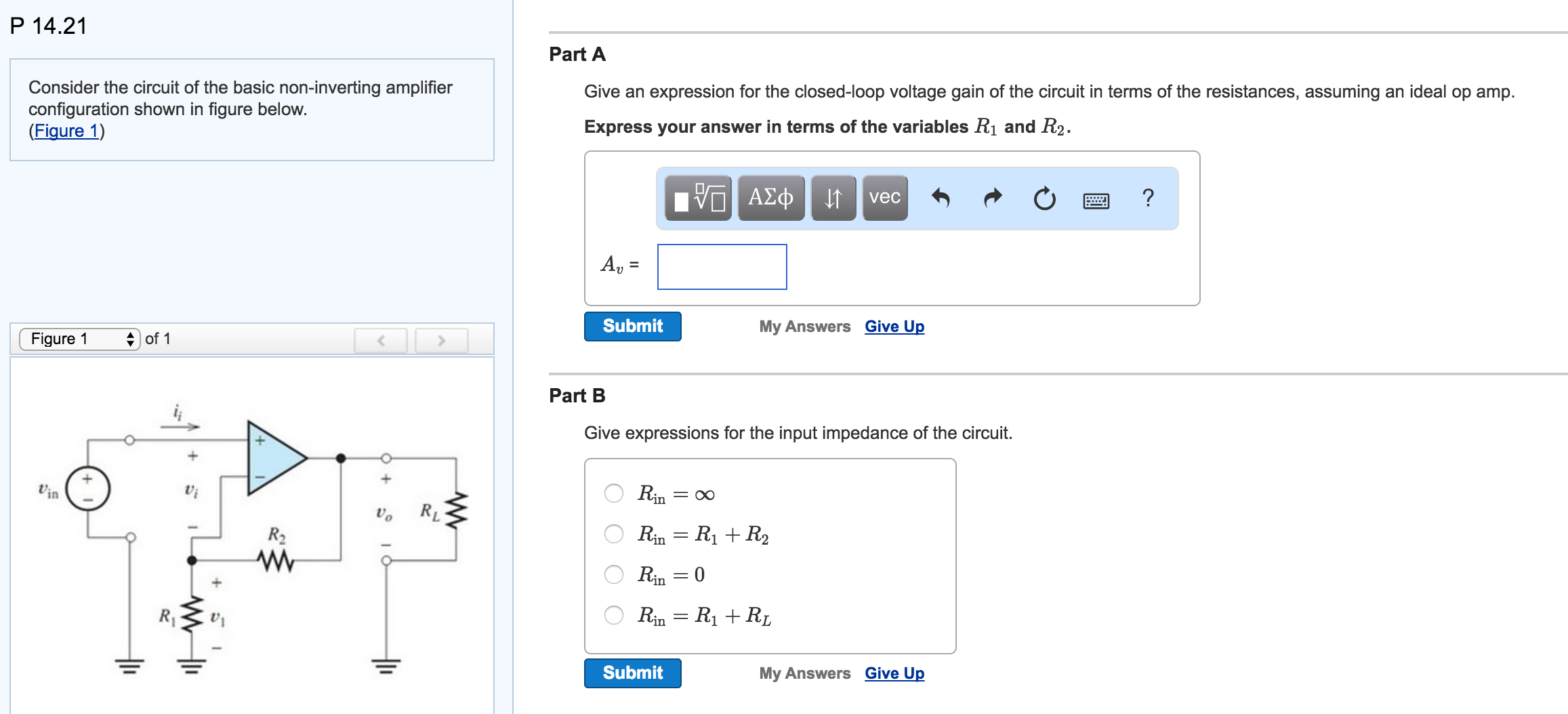
Solved Consider the circuit of the basic non-inverting ...
Open Loop Op-Amp Configuration Questions and Answers - Sanfoundry

Inverting Operational Amplifier - The Inverting Op-amp
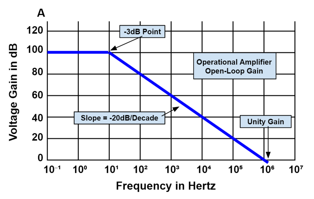
What are open-loop and closed-loop gains of an op-amp ...
Inverting and Non-inverting Amplifier and Their Differences

Active Low Pass Filter: Design and Applications | Electrical4U
The Ultimate Guide to Operational Amplifiers - HardwareBee
4.2: Inverting and Noninverting Amplifiers - Engineering ...
Operational Amplifier Basics, Types and Uses| Article | MPS
0 Response to "36 select the correct circuit diagram of the basic inverting amplifier configuration."
Post a Comment