38 paragon defrost timer 8145 20 wiring diagram
PDF Commercial Refrigeration Defrost Controls - Supco S814520 8145-20 6145-20 SUPCO Paragon Precision S804100 8041-00 6041-00 S804120 8041-20 6041-20 S804500 8045-00 6045-00 S804520 8045-20 6045-20 Wiring using differential of SPDT thermostat Wiring using 120V or 240V single phase line compressor thermostat closed during defrost. L 120 N L1 208-240 L2 S814500 & S814520 Wiring Diagrams Hot Gas ... INSTALLATION DATA 8000 SERIES AUTO VOLTAGE ... On the timer wheel, choose a defrost cycle starting time. ... the wiring diagram chosen. ... 8047-00 and 8047-20. Electric Heat Defrosting. 8145-AV.6 pages
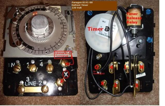
Paragon Defrost Timer 8145-00 Wiring Diagram The DTAV40 may also be used to replace Paragon and Precision series time terminated defrost . Paragon Defrost Timer Wiring Walk In Freezer Car Diagrams. Grasslin defrost timer wiring diagram book of paragon 20 dia arcnx paragon defrost timer wiring diagram clock and freezer to 20 paragon defrost timer wiring diagram fresh 20 questions answers with.
Paragon defrost timer 8145 20 wiring diagram
PDF Freezer Defrost Timer Wiring Diagram w10822278 defrost timer partselect. 8145 20 wiring diagram wiring diagram. freezer defrost timer wiring diagram throughout agnitum me. frigidaire 215846602 defrost timer appliancepartspros com. wiring diagram defrost timer for a 4 / 38 Paragon 8145 20 Defrost Timer Wiring Diagram on Paragon 8145 20 Defrost Timer Wiring Diagram. Adjustable Defrost Cycle Duration: 4 to minutes in S and Paragon Wiring Diagrams Electric Heat Defrosting S & S Series. tors, Paragon® Commercial Defrost Controls Choice TM in Defrost Timers. SLINE 2. Paragon Defrost Timer 8145 20 Wiring Diagram Gallery Collection of paragon defrost timer 8145 20 wiring diagram. A wiring diagram is a simplified traditional photographic depiction of an electrical circuit. It reveals the elements of the circuit as streamlined shapes, and also the power as well as signal links in between the tools.
Paragon defrost timer 8145 20 wiring diagram. Paragon 8145 20 Defrost Timer Wiring Diagram - easywiring Paragon 8145 20 defrost timer wiring diagram. It reveals the elements of the circuit as simplified forms and also the power and also signal connections between the tools. Collection of paragon defrost timer 8145 20 wiring diagram. 8047 20 208 240 for electric heat defrosting auxiliary contact models 50 hz available open open closed 4 110 min. Paragon Defrost Timer 8145 20 Wiring Diagram - schematron.org Find solutions to your paragon defrost timer 20 wiring diagram question. Get free help, tips & support from top experts on paragon defrost timer Adjustable Defrost Cycle Duration: 4 to minutes in S and Paragon Wiring Diagrams Electric Heat Defrosting S & S Series. how to test paragon 20 defrost timer rh waterheatertimer org Paragon 20 Wiring Schematic Paragon Time Clock tors, Paragon ... PDF Auto-Voltage Defrost Timer - United Components systems where the defrost is terminated by the timer or when the coil is frost free, as sensed by a ... Paragon 9045-00 8043-00 8143-20 8046-20 8145-00 8041-00 ... Wiring Diagrams Intermatic SKU Description Enclosure Time Switch features PDF 8145 20 Electric Defrost Diagram April 15th, 2019 - Collection of paragon defrost timer 8145 20 wiring diagram A wiring diagram is a streamlined traditional pictorial depiction of an electric circuit It reveals the elements of the circuit as simplified forms and also the power and also signal connections between the tools
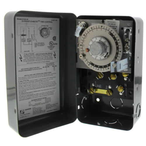
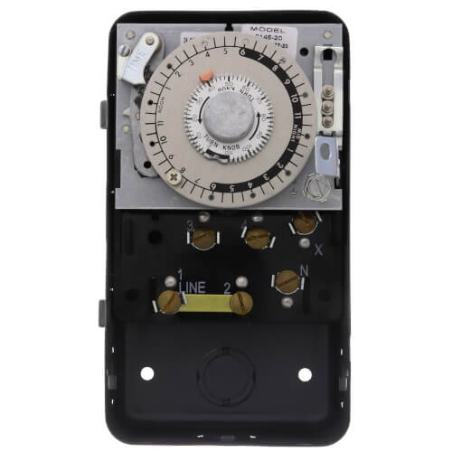
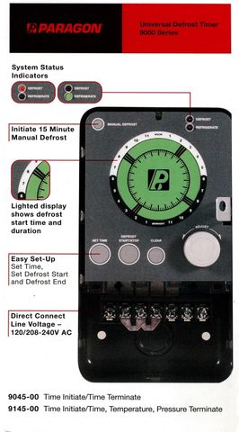
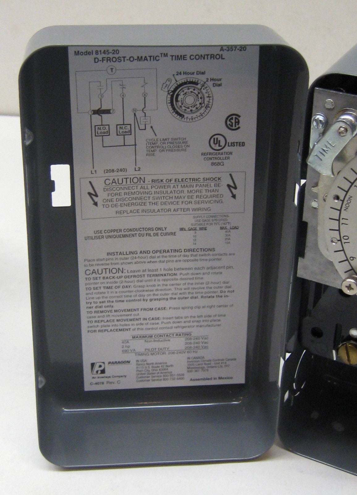
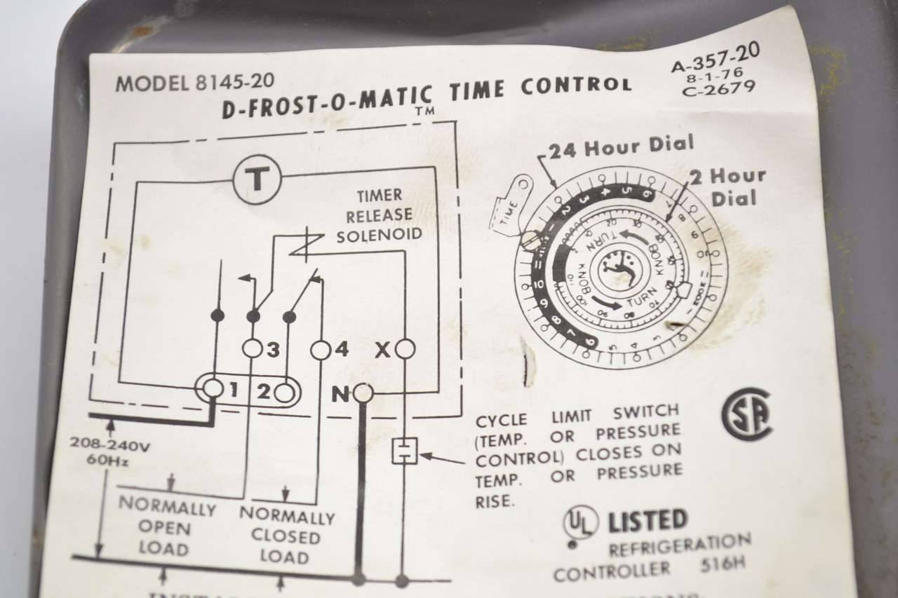
Paragon Defrost Timers 8145 and 9145 Overview - YouTube Basic information about the Paragon Mechanical and Electronic Defrost Timers Paragon 8141 00 Wiring Diagram Download - Wiring Diagram ... Name: paragon 8141 00 wiring diagram - Defrost Clock Wiring Diagram And Freezer Timer To Paragon 8145 20 Throughout 8141 00 Time 5; File Type: JPG; Source: natebird.me; Size: 119.60 KB; Dimension: 1059 x 893 PDF Paragon Electric Timers Manual [PDF] Paragon Timer 8145 20 Wiring Diagram - Free Files. 8145-20ex - Paragon Electric 8145-20ex Timer .... Jul 21, 2018 — Ec4004 Paragon Electric Timer Manual 5,6/10 42reviews. Paragon Electric EC4000 Series Timers Time Controls 24-Hour or 7-Day Interval .... mechanical defrost Timer Wiring Jumper Wire Normalty Closed MODELS 8141-00 AND 8141-20 Wiring using 120V Or 240V single phase line with auxiliary fan circuit. MODELS 8145-00 AND 8145-20 CYCLE 1-2 Normally closed thermostat used with defrost heater. Wiring using 120V or 240V Single phase fine compressor voltage common to timer. ELECTRIC HEAT DEFROSTING
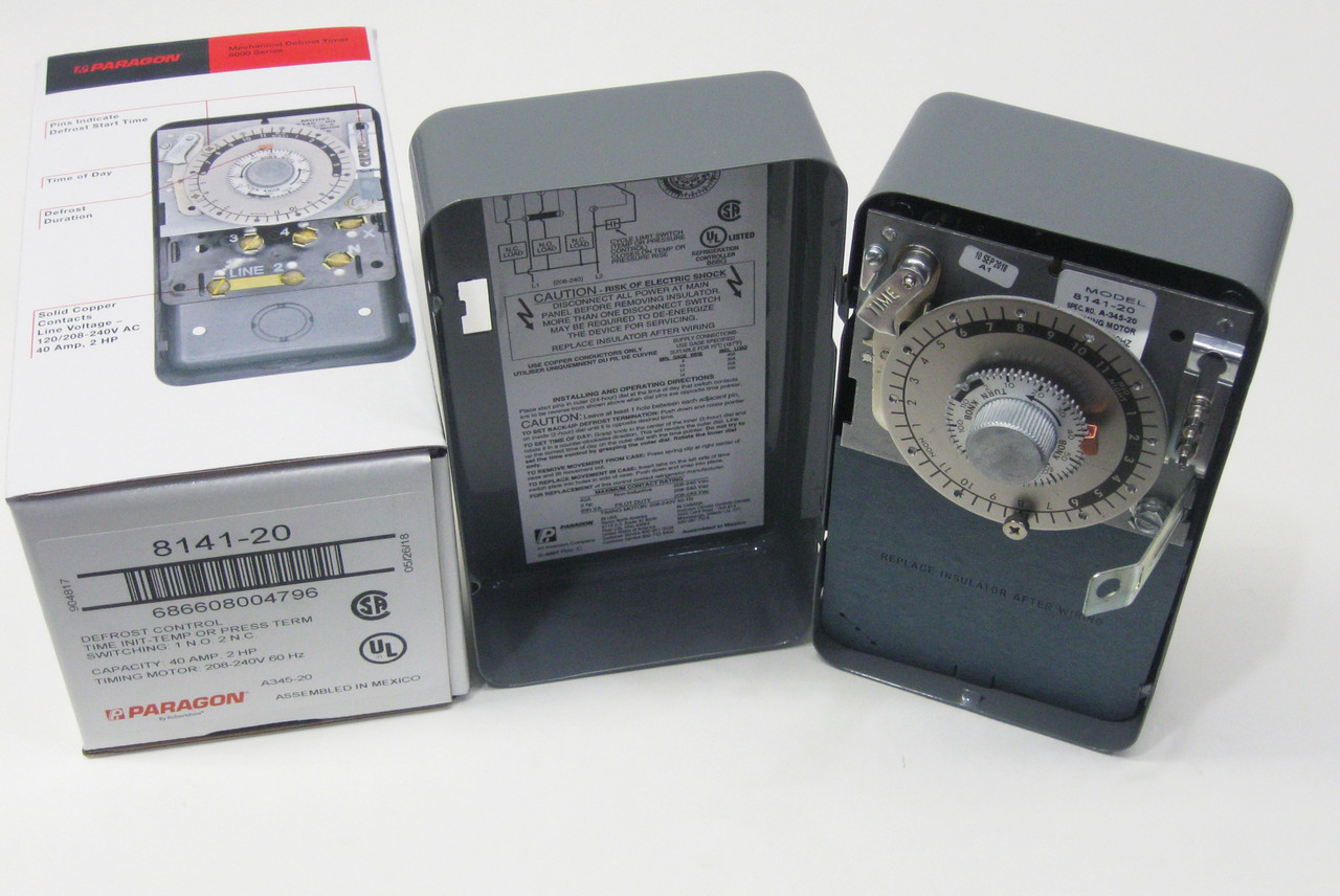
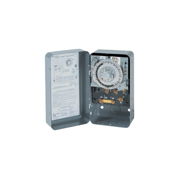
Products | 8145-20 - Robertshaw 8145-20 8000 Series Defrost Timers The Paragon® 8000 Series Commercial Defrost Controls are designed for commercial freezers and refrigerators to provide automatic defrost capability. They accommodate various types of defrost systems including electric defrost heaters, hot gas, and compressor off cycle. Features and Benefits 8145-20 - Paragon 8145-20 - 208/240V Defrost Timer Paragon 8145-20 - 208/240V Defrost Timer - Designed for commercial freezers and refrigerators, Paragon commercial defrost controls provide automatic defrost capability. They accommodate various types of defrost systems including electric defrost heaters, hot gas and compressor off cycle. Time initiated, temperature or pressure terminated High ... PDF 8000 Auto Voltage Defrost Series Timers • Defrost times programmable in 15-minute intervals with captive trippers • Heavy-duty steel enclosure with knockouts (on the bottom, back and side) and hasp • Mechanism only model available 8145-AV-M The Paragon® 8000 Series Auto Voltage Defrost Timer is designed for commercial freezers and refrigerators. Paragon Defrost Controls PDF Paragon 8045-20 defrost timer wiring diagram Collection of paragon defrost timer 8145 20 wiring diagram. The defrost timer acts as a clock, that switches the refrigerator from the freezing cycle to the defrost cycle and back. EC series programming manual shows wiring, explains keypad, has steps for setting current time, and shows 24 steps for programming timer. DC could flow not just ...
208/240V Defrost Timer
REFRIGERATION . Customer Service 1.800.304.6563. REFRIGERATION. D4. Product Drawings. 8047-00 and 8047-20. Electric Heat Defrosting. 8145-AV.3 pages

I have an 8141 Paragon defrost timer and have to replace it ...
8145 20 Timer Wiring Diagram 8145 20 Timer Wiring Diagram S and Paragon Available in 6-pack display. Wiring Diagrams Electric Heat Defrosting S & S Series. COMP. HEATER. FAN. L N. The Paragon® defrost and the Tork® electric timers offer versatility and unbeatable Electric Heat,. Hot Gas or Compressor Shutdown. Closed . Open. None. Temp or .
Paragon 8141-20 Defrost Control Commercial Refrigeration Timer
MECHANICAL DEFROST TIMER 8000 Series - Everwell Parts 8047-20 208-240 For Electric Heat Defrosting (Auxiliary Contact Models), 50 Hz available Open Open Closed 4-110 Min. MECHANICAL DEFROST TIMER 8000 Series Defrost Duration Solid Copper Contacts Line Voltage - 120/208-240V AC 40 Amp, 2 HP Pins Indicate Defrost Start Time Time of Day Model Number Time Initiated, Time Terminated Time Initiated ...

Paragon 8141-20 Defrost Control Commercial Refrigeration Timer
Paragon Hardware and Accessory Repair Questions ... - Fixya Open following links to identify timer and download wiring diagram: ... Paragon 8145-20 Defrost Timer. 72 Questions. Paragon Amf 7008-00 Timer 7 Day 120 Volt Timing Motor. 24 Questions. Paragon 4001-0G Defrost Timer. 11 Questions. Paragon 7007-00 Electromechanical Indoor 7 Day Timer.
How to test Paragon 8145-20 defrost timer.
Paragon 8145 00 Wiring Diagram - easywiring Paragon defrost timer 8145 20 wiring diagram paragon defrost timer wiring furthermore paragon defrost timer 8145 rh beinclover co. Here is a picture gallery about 20 wiring diagram complete with the description of the image please find the image you need. Wiring diagram sheets detail. Models 8143 00 and 8143 20 wiring.

Paragon 8000 Series English | PDF | Switch | Timer
PDF The First and Only Multi-Voltage Defrost Timer The defrost timer shall be housed in a NEMA 3R indoor/ outdoor plastic enclosure. The relay output will ... 8145-20 6145-20 8041-20 6041-20 8043-20 6043-20 8045-20 6045-20 8046-20 8047-20 6047-20 ... DTMV Time/Time-Electric Defrost Wiring Diagram 8041 Replacement 2 S1 Position A with 8041 Label Applied 8041 3 LABEL L I N E FAN N THERMOSTAT
PARAGON 8145-20,8145-20,PARAGON ELECTRIC CO,Field Controls ...
Robertshaw | Products | 8145-AV This all-in-one auto voltage defrost timer replaces over 40 competitive voltage-specific mechanical defrost timers, eliminating the need for a separate short cycle timer and single-phase voltage monitor. The 8145-AV will become a mainstay in any contractor's truck. The 8145-AV reduces installation time, and minimizes the number of SKUs to stock.
Robertshaw 8000 Series Auto Voltage Defrost Timer manual ...
Paragon time clock 8145-20 manual - Co-production ... None Initiate 15 minute manual defrost. Mar 18, 2018 - Paragon defrost timer 8145 20 wiring diagram intermatic defrost timers and manuals. Zoom out/reset put photo at full zoom then double click. T101 24 hour timer Have a manual for Paragon Timers? Item # 5X459, Mfr. Grasslin Intermatic G8145-20 Paragon 8145-20 240V Indoor metal (Time -On,Temp.
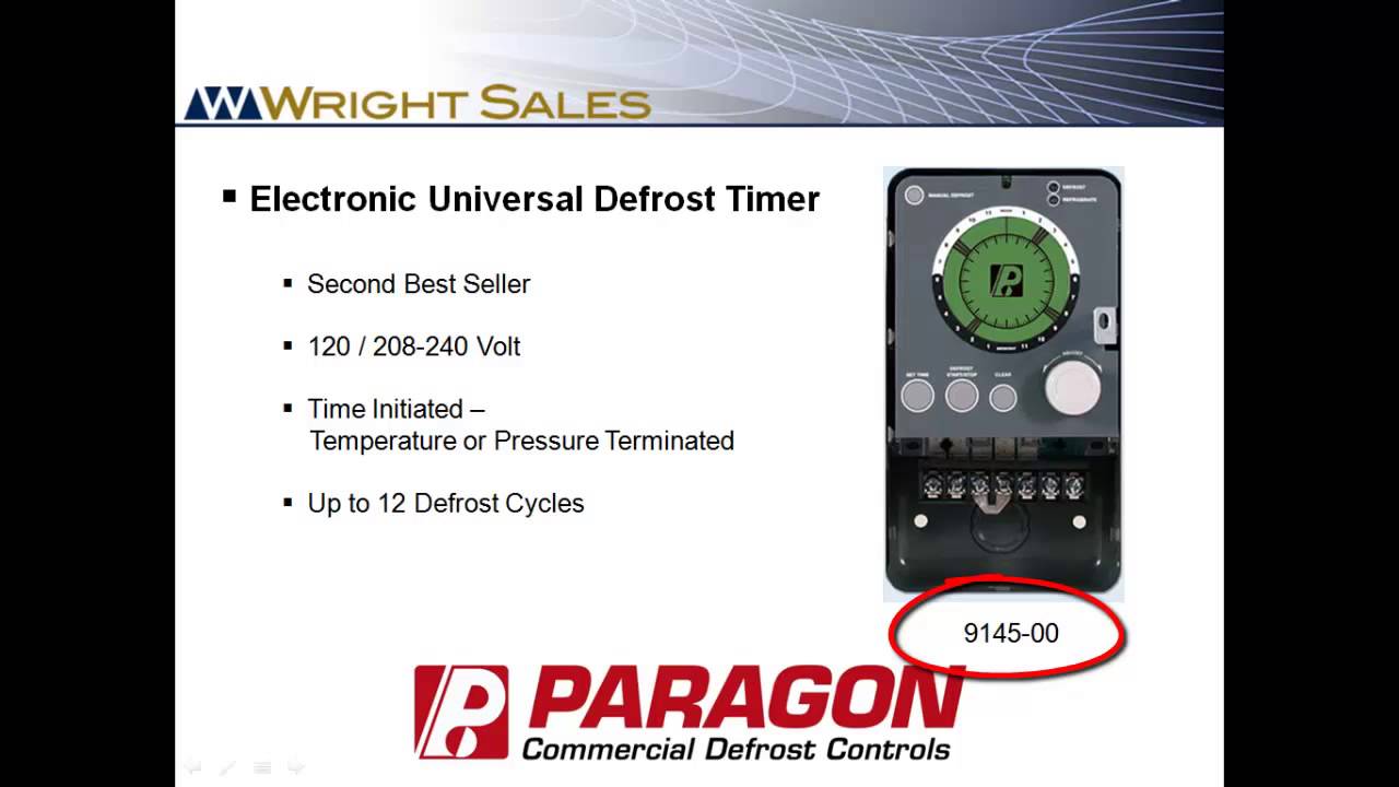
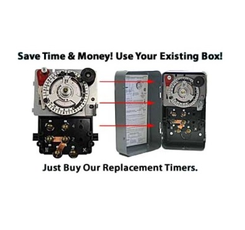
Paragon Defrost Timers 8145 and 9145 Overview
Intermatic Defrost Timers - Paragon Defrost Timers - Supco ... Heavy Duty Silver Plated Defrost Timer, 2 HP NEMA-1 (240V) G8145-20 Heavy Duty Silver Plated Defrost Timer, 2 HP NEMA-1 (240V) SKU: G8145-20 Intermatic SKU : G8145-20
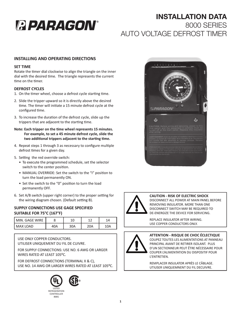
INSTALLATION DATA 8000 SERIES AUTO VOLTAGE DEFROST TIMER
Wiring a defrost timer in series with the contactor or ... Defrost timer also shuts off evap fans and energizes defrost heaters. Evap has termination stat to shut off heaters if they get too hot and often kick defrost timer out on the X terminal. Fans are wired though same little 3 wire stat and won't come on till evap gets cold again after defrost.
208/240V Defrost Timer
PARAGON Defrost Timer Control, 208/240V AC Voltage, 40 A ... PARAGON. Defrost Timer Control, 208/240V AC Voltage, 40 A Amps, SPDT. Item # 5X459. Mfr. Model # 8145-20. UNSPSC # 39121523. Catalog Page # 3018 3018. Country of Origin Mexico. Country of Origin is subject to change. Choice of 3 contact arrangements for electric heat, compressor shutdown, or hot gas defrost.

Amazon.com: Supco, temporizador comercial completo para ...
PDF Paragon Timers Manual Apr 28, · Web search for 'Paragon ' Pex supply sells Volt defrost timer for $, and Grainger for $ Open following link for manual, . Description: Paragon Defrost Timer Wiring Diagram Paragon Defrost Timer Wiring regarding 20 Wiring Diagram, image size X px, and to view image details please click the image. 8145 20 Timer Wiring Diagram
PARAGON COMMERCIAL DEFROST TIMER DIGITAL
PDF 9145 / 9045 UNIVERSAL Series DEFROST TIMERS The Paragon® 9045-00 and 9145-00 Universal Defrost Timers are the only multi-voltage defrost timers engineered to refrigeration standards. At four defrosts per day, the Paragon Universal Defrost Timer switches last 16 years longer than competitive offerings. • Real-time clock • Initiate 15 minute manual defrost • System status indicators
Commercial Refrigeration Temperature and Defrost Controls
How to test Paragon 8145-20 defrost timer. - Waterheatertimer ... How to test Paragon 8145-20 defrost timer. Timer dial rotates continuously, and keeps good time. X-3596 Trippers are attached to edge of dial. When.1 page
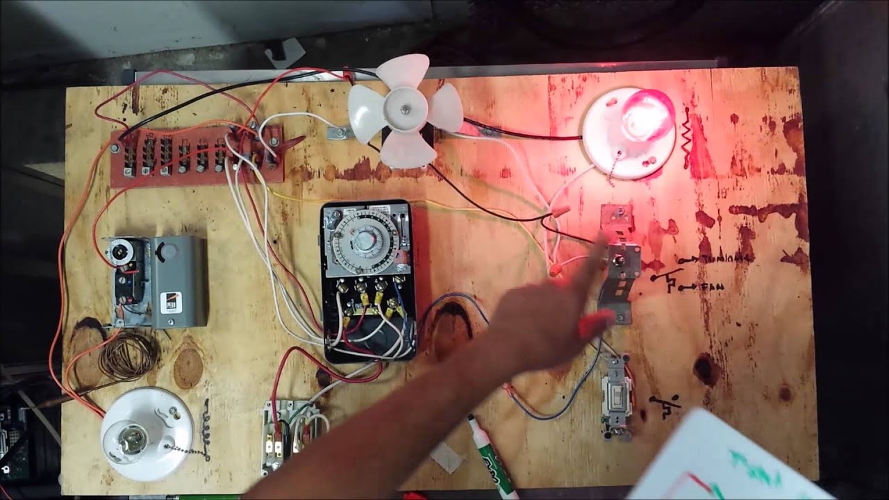
Freezer Defrost Timer Live Operation
Paragon Defrost Timer 8145 20 Wiring Diagram Gallery Collection of paragon defrost timer 8145 20 wiring diagram. A wiring diagram is a simplified traditional photographic depiction of an electrical circuit. It reveals the elements of the circuit as streamlined shapes, and also the power as well as signal links in between the tools.
Heating, Air & Refrigeration Discussion - HVAC-Talk
Paragon 8145 20 Defrost Timer Wiring Diagram on Paragon 8145 20 Defrost Timer Wiring Diagram. Adjustable Defrost Cycle Duration: 4 to minutes in S and Paragon Wiring Diagrams Electric Heat Defrosting S & S Series. tors, Paragon® Commercial Defrost Controls Choice TM in Defrost Timers. SLINE 2.
Paragon 8145-20 Defrost Control Commercial Refrigeration Timer
PDF Freezer Defrost Timer Wiring Diagram w10822278 defrost timer partselect. 8145 20 wiring diagram wiring diagram. freezer defrost timer wiring diagram throughout agnitum me. frigidaire 215846602 defrost timer appliancepartspros com. wiring diagram defrost timer for a 4 / 38
Defrost Time Controls / HVAC/R Defrost Time Controls / HV AC/R
AUTO VOLTAGE DEFROST TIMERS 8000 SERIES
INSTALLATION DATA 8000 SERIES AUTO VOLTAGE DEFROST TIMER
AUTO VOLTAGE DEFROST TIMERS 8000 SERIES
Precision Defrost Timers - Replacements Only 6 Pack

HOW FREEZER DEFROST TIMER OPERATES - PART 2
Commercial Refrigeration Temperature and Defrost Controls
Untitled
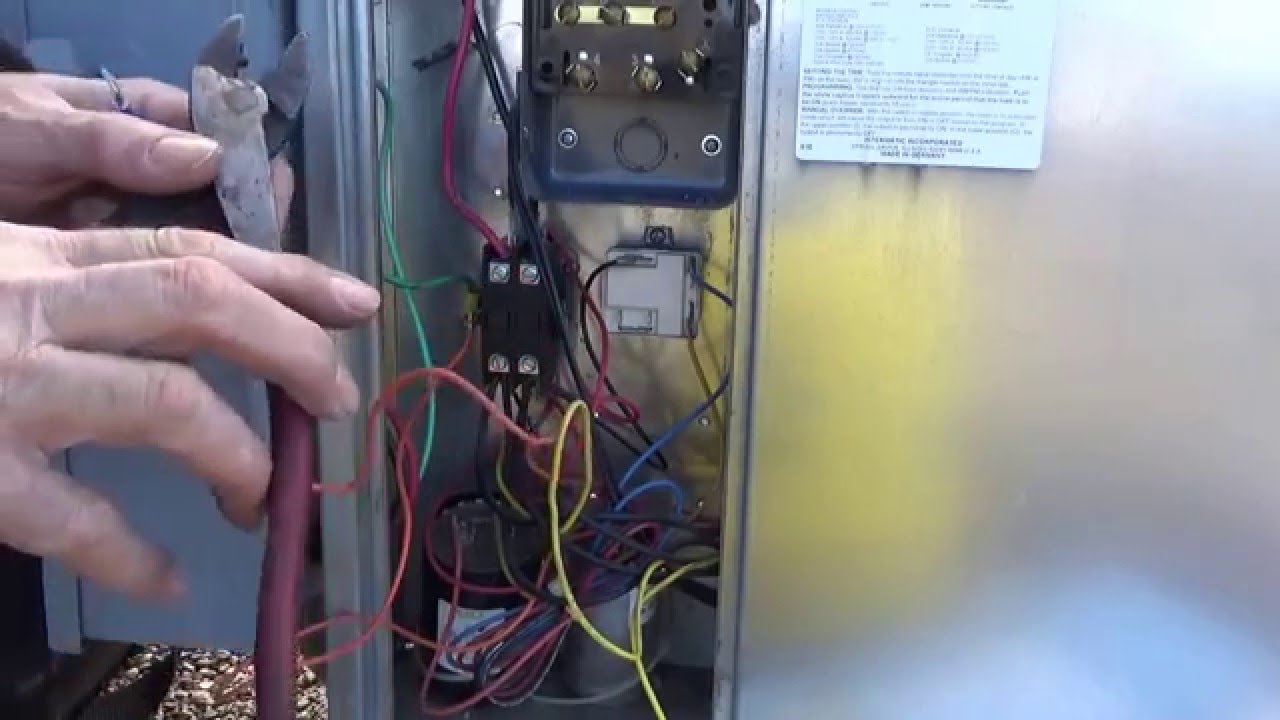
Defrost time clock replacement and wiring
Part Number: E316008_J

Precision Multiple Controls Official Website - Your Source ...

Timers – Affinity Supply

PARAGON 8145-20B DEFROST Control,208/240V - £106.78 | PicClick UK
INSTALLATION DATA 8000 SERIES AUTO VOLTAGE DEFROST TIMER

Defrost Timer Product Sheet.indd

Intermatic Defrost timers and manuals
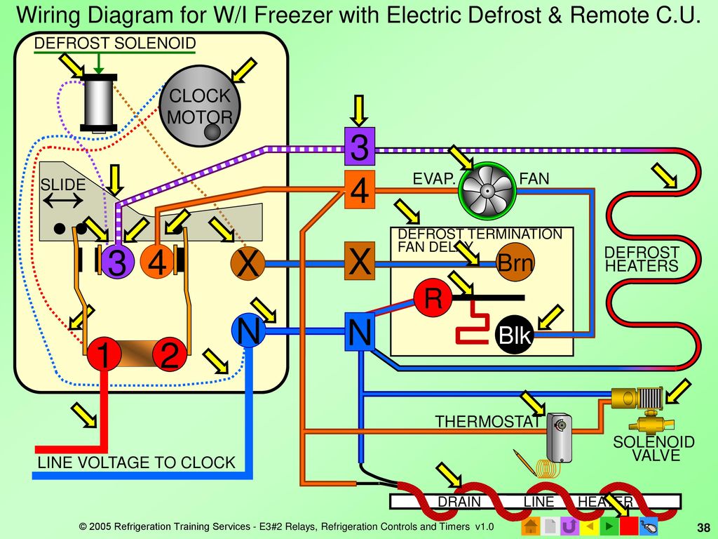
E3 HVACR Controls and Devices - ppt download

SOLVED: Trying to replace a 8045-20 w/ 8145-20 need wiring ...
Appliance411 FAQ: How does a Frost Free Refrigerator's ...
Paragon 8145-20 D-frost-o-maic Time Control Defrost 208-240v ...

SOLVED: Paragon 8141-00 defrost timer wont turn. - Fixya
0 Response to "38 paragon defrost timer 8145 20 wiring diagram"
Post a Comment