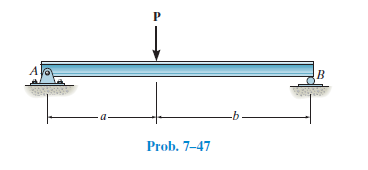
38 draw the shear diagram for the beam. set p = 600 lb, a = 5 ft, b = 7 ft.
Transcribed image text: Draw the shear diagram for the beam. Set P - 600 lb, a = 5 ft, b -7 ft. Click on "add discontinuity" to add discontinuity lines. 06.12.2021 · Set m0 500 nm l 8 m. 4.3 shear moment equations and shear moment diagrams the determination of the internal force system acting at a given section of a beam: The bending moment diagram is as follows: Draw the shear diagram for 0 x 14 ft of the compound beam. 778 draw the shear and moment diagram. Problem 1 draw the shear force and bending ...
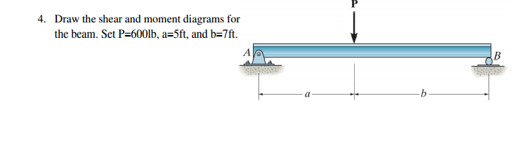
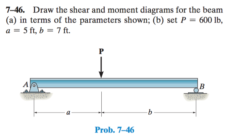
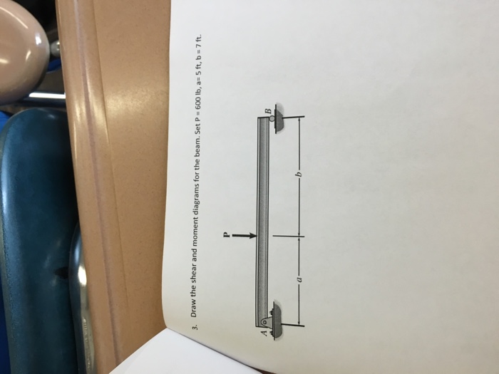
Question: draw the shear and moment diagram for the beam (a) in terms of the parameters shown; (b) set P= 600lb, a=5ft, b=7ft ...

Draw the shear diagram for the beam. set p = 600 lb, a = 5 ft, b = 7 ft.
Positive bending moment diagram drawn BELOW the beam SHEAR FORCE & BENDING ... Then, draw the shear force diagram (SFD) and bending moment diagram (BMD). b) If P = 20 kN and L = 6 m, draw the SFD and BMD for the beam. P kN L/2 L/2 A B EXAMPLE 4 . P kN L/2 L/2 R ... then draw the shear force diagram (SFD) and bending moment diagram (BMD). 5 kN/m ... Free online beam calculator for generating the reactions, calculating the deflection of a steel or wood beam, drawing the shear and moment diagrams for the beam. This is the free version of our full SkyCiv Beam Software. This can be accessed under any of our Paid Accounts, which also includes a full structural analysis software. Transcribed image text: Problem 7.47 Part A Draw the shear diagram for the beam. Set P 600 lb, 5 ft, b 7 ft. Click on "add discontinuity" to add ...
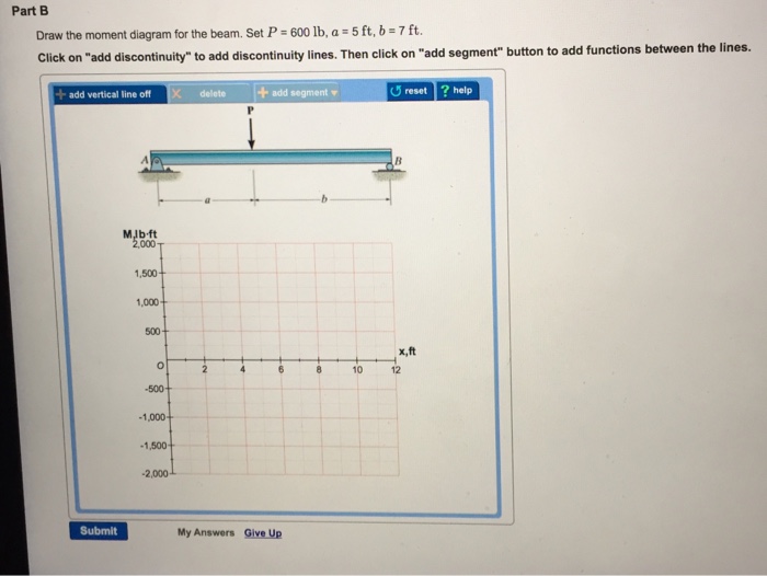
Draw the shear diagram for the beam. set p = 600 lb, a = 5 ft, b = 7 ft.. Shear and moment diagrams and formulas are excerpted from the Western Woods Use ... L = span length of the bending member, ft. R = span length of the bending member, in. M = maximum bending moment, in.-lbs. P = total concentrated load, lbs. R = reaction load at bearing ... 7-48 A R 1 Shear a b Figure 25 Beam Fixed at Both Ends-Concentrated ... A concentrated load, such as P in Fig. 4.1(a). In contrast a distributed load is applied over a finite area. If the distributed load acts on a very narrow area, the load may be approximated by a line load. The intensity w of this loading is expressed as force per unit length (lb/ft, N/m, etc.) in this problem, we have a beam that is simply supported. Honey jam Here there is a point load at the at the middle here and again I because I made the value negative, actually, throughout the arrow positive. And so this point load is at a distance A from the right and left and and then it's at a distance. Be from the right. So if we try to, free by diagram and forces some forces in some ... 12 10 Part B Draw the moment diagram for the beam. Set P 600 lb, a 5 ft, b-7 ft. Click on "add discontinulty" to add discontlnulty lines.
Transcribed image text: Part A Draw the shear diagram for the beam. Set P = 600 lb, a = 5 ft, b = 7 ft. Click on "add discontinuity" to add discontinuity lines. Then click on "add segment" button to add functions between the lines. + + O @ b No elements selected V, lb 500 400 300 200 100 2, ft 0+ 0 -100- 2 4 6 8 10 12 -200 -300 -400 -500 Part B Draw the moment diagram for the beam. Draw the shear and moment diagrams for the beam (a) in terms of the parameters shown; (b) set P = 600 lb, a = 5 ft, b = 7 ft. 2 | P a g e 2. Draw the shear and moment diagrams for the cantilevered beam. 12.08.2016 · Images Of Draw The Shear Diagram For The Beam Set P 600 Lb A 5 Ft B 7 Ft, Easy Drawing, Images Of Draw The Shear Diagram For The Beam Set P 600 Lb A 5 Ft B 7 Ft Transcribed image text: HW 15 Problem 7.47 Part A Draw the shear diagram for the beam. Set P- 600 lb, a 5 ft, b 7ft Click on "add discontinuity" to add ...
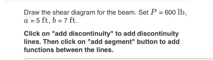
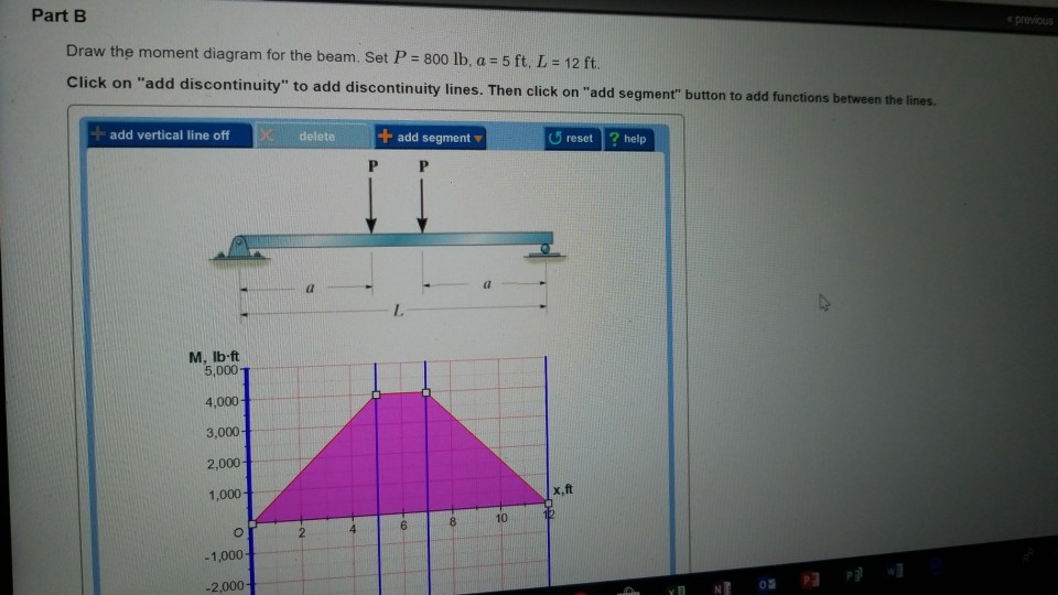
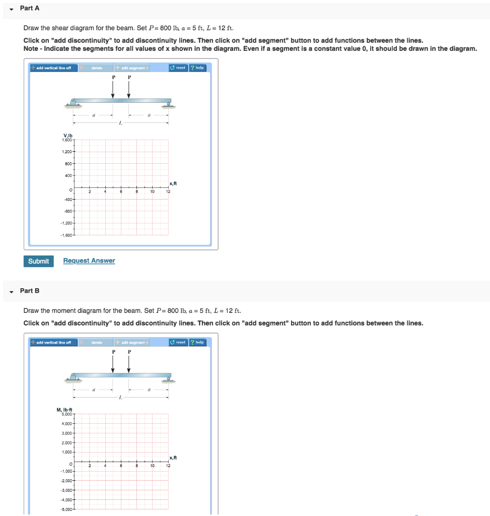
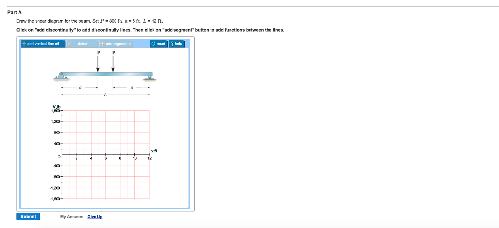
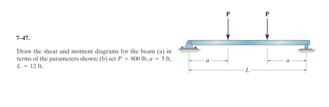
08.05.2017 · Mechanical Engineering questions and answers. Draw the shear diagram for the beam. Set P = 800 lb, a = 5 ft. L = 12 ft. Click on "add discontinuity" to add discontinuity lines. Then click on "add segment" button to add functions between the lines. Draw the moment diagram for the beam. Shear and Moment Diagrams 10 ft. A 600 lb. 4,000 lb. ft. 5 ft. 5 ft. B Draw the shear and moment diagrams for the following beam Shear and Moment Diagrams Draw the shear and moment diagrams for the following beam 18 ft. A B 4 k/ft. Shear and Moment Diagrams 12 ft. A 4 k/ft. 60 k 8 ft. 100 k ft. Draw the shear and moment diagrams for the ... Mechanical Engineering questions and answers. Draw the moment diagram for the beam. Set P = 600 lb. a = 5 ft. b = 7 ft Click on add discontinuity to add discontinuity lines. Then click on add segment button to add functions between the lines. Draw the moment diagram for the beam. Draw the shear and moment diagrams for the beam (a) in terms of the parameters shown; (b) set P = 600 lb, a = 5 ft, B = 7 ft.
Draw The Shear Diagram For The Beam Set P 800 Lb A 5 Ft L ...
Very so for the values that made gave Pius £600 a is and again I use p equals minus £600. Just because I herro I was assuming it was positive here, um, during up And so in £606 a is five feet and he is seven feet.

35 Draw The Shear Diagram For The Beam. Set P = 800 Lb, A ...
6–5. Draw the shear and moment diagrams for the beam. 2 m 3 m 10 kN 8 kN 15 kN m M (kN m) x x ... overhanging beam. 3 ft 3 ft 200 lb/ft 400 lb 6 ft 400 lb A B M (lb ft) x (ft) V (lb) 0 400 0 12 x (ft) 600 1200 1200 300 600 400 3 6 369 12 9 Ans: Hibbeler_Chapter 6_Part 1 (487-517).qxd 2/12/13 11:07 AM Page 499. 510
Answered: Prob. 7-47 | bartleby
No portion of this material may be reproduced, in any form or by any means, without permission in writing from the publisher. 7–79. Draw the shear and moment diagrams for the 300 lb 200 lb/ft cantilever beam.

Michael Heath-Caldwell M.Arch - 1948 Journal for the Use ...
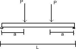
B P A C L a b PROBLEM 5.2 For the beam and loading shown, (a) draw the shear and bending-moment diagrams, (b) determine the equations of the shear and bending-moment curves. SOLUTION Reactions: C 0: 0 Pb MLAbP A L A 0: 0 Pa MLCaP C L From A to B, 0 x a y 0: 0 Pb FV L Pb V L J 0: 0 Pb MMx L Pbx M L
Solved: Draw The Shear Diagram For The Beam. Set P = 600 L ...
*7—56. Draw the shear and moment diagrams for the cantilevered beam. 300 1b - diagram of the beam's left through an arbitrary shown in fig. b will be to write the and mcnnent quations. The inœnsity the triangldar útributed load at of sectioning is — = 3333r Referring Fig. b , o V = {-300- 1b — +3001-0 The shear and diagrams shown in ...

Editor@pambazuka.org on Tapatalk - Trending Discussions ...
Question: Draw the shear and moment diagrams for the beam. Set P = 600 lb, a = 5 ft, and b = 7 ft. This problem has been solved!
35 Draw The Shear Diagram For The Beam. Set P = 800 Lb, A ...
09.01.2022 · Shear and moment diagrams and formulas are excerpted from L = span length of the bending member, ft. R = span length of the bending member, in. M = maximum bending moment, in.-lbs. P = total concentrated load, lbs. R = reaction load at bearing point, lbs. V = shear force, lbs. W = total uniform load, lbs. w = load per unit length, lbs./in. Δ = deflection or …

35 Draw The Shear Diagram For The Beam. Set P = 800 Lb, A ...
6—25. Draw the shear and moment diagrams for the beam- The two segments are joined together at B. 8 kip 3 kip,ft 5 ft *6—20. Draw the shear and moment diagrams for the beam, and determine the shear and moment throughout the beam 10 kip 2 kip/ft g Kip 8 kip 40 kip.ft as functions of x. Support Reactions: As shown on FBD. Shear and Moment ...

35 Draw The Shear Diagram For The Beam. Set P = 800 Lb, A ...
Draw the shear and moment diagrams for the beam (a) in terms of parameters shown; (b) set P = 600 lb, a = 5 ft, b = 7 ft Drawing for the Shear and Bending Moment Diagram: In this problem, I find ...

Draw The Shear Diagram For The Beam Set P 800 Lb A 5 Ft L ...
The beam consists of two segments pin connected at B. Draw the shear and moment diagrams for the beam. 700 lb 150 lb/ft 8 ft 626 C B A 4 ft 800 lb ft 6 ft 7 Solutions 44918 1/27/09 10:39 AM Page 627 © 2010 Pearson Education, Inc., Upper Saddle River, NJ.

Editor@pambazuka.org on Tapatalk - Trending Discussions ...
Problem 412 Beam loaded as shown in Fig. P-412. [collapse collapsed title="Click here to read or hide the general instruction"]Write shear and moment equations for the beams in the following problems. In each problem, let x be the distance measured from left end of the beam. Also, draw shear and moment diagrams, specifying values at all change of loading positions and at

Michael Heath-Caldwell M.Arch - 1948 Journal for the Use ...
Draw the shear diagram for the beam. Set P = 600 lb, a = 5 ft, b = 7 ft. Click on "add discontinuity" to add discontinuity lines. Then click on "add segment" button to add functions between the lines. P B b V, lb 500 400 300 200 100 0 0 1, ft 4 os 00 10 12 N -1001 -200 -300 -400 -500 Draw the moment diagram for the beam.
Draw The Shear Diagram For The Beam Set P 800 Lb A 5 Ft L ...
Transcribed image text: Problem 7.47 Part A Draw the shear diagram for the beam Set P 600 lb, a 5 ft, b ft Click on "add discontinuity" to add discontinuity ...

Editor@pambazuka.org on Tapatalk - Trending Discussions ...
Solution for Draw the shear and moment diagrams for the beam. 600 lb/ft B 3 ft 6 ft 3 ft. menu. Products. Subjects. Business. Accounting. Economics. Finance ... Draw the shear and moment diagrams for the beam. 600 lb/ft B 3 ft 6 ft 3 ft. close. ... A tacheometer was set up at B.M and the following observations were made with a leveling staff ...

Michael Heath-Caldwell M.Arch - 1948 Journal for the Use ...
Draw the shear and moment diagrams for the beam shown in Fig. 6–7a. (a) L w 0 w —— 2 0 L (b) 2– L 3 w —— 2 0 L — 3 w 0 L2 w 0 Solution Support Reactions.The distributed load is replaced by its resultant force and the reactions have been determined as shown in Fig. 6–7b. Shear and Moment Functions.A free-body diagram of a beam ...
Solved: Problem 7.47 Part A Draw The Shear Diagram For The ...
Transcribed image text: Problem 7.47 Part A Draw the shear diagram for the beam. Set P 600 lb, 5 ft, b 7 ft. Click on "add discontinuity" to add ...

Draw The Shear Diagram For The Beam Set P 800 Lb A 5 Ft L ...
Free online beam calculator for generating the reactions, calculating the deflection of a steel or wood beam, drawing the shear and moment diagrams for the beam. This is the free version of our full SkyCiv Beam Software. This can be accessed under any of our Paid Accounts, which also includes a full structural analysis software.

Editor@pambazuka.org on Tapatalk - Trending Discussions ...
Positive bending moment diagram drawn BELOW the beam SHEAR FORCE & BENDING ... Then, draw the shear force diagram (SFD) and bending moment diagram (BMD). b) If P = 20 kN and L = 6 m, draw the SFD and BMD for the beam. P kN L/2 L/2 A B EXAMPLE 4 . P kN L/2 L/2 R ... then draw the shear force diagram (SFD) and bending moment diagram (BMD). 5 kN/m ...
35 Draw The Shear Diagram For The Beam. Set P = 800 Lb, A ...

Draw The Shear Diagram For The Beam Set P 800 Lb A 5 Ft L ...

Solved: Draw The Moment Diagram For The Beam. Set P = 600 ...
Mechanical Engineering Archive | March 15, 2017 | Chegg.com

Michael Heath-Caldwell M.Arch - 1948 Journal for the Use ...
Solved: Draw The Shear And Moment Diagrams For The Beam. S ...
Solved: Please Show How To Get Reaction Forces As Well As ...
35 Draw The Shear Diagram For The Beam. Set P = 800 Lb, A ...

Draw The Shear Diagram For The Beam Set P 800 Lb A 5 Ft L ...

Draw the shear and moment diagrams for the beam (a) in ...

35 Draw The Shear Diagram For The Beam. Set P = 800 Lb, A ...
Solved: Draw The Shear And Moment Diagrams For The Beam. S ...
Draw The Shear Diagram For The Beam Set P 800 Lb A 5 Ft L ...
35 Draw The Shear Diagram For The Beam. Set P = 800 Lb, A ...
Draw The Shear Diagram For The Beam Set P 800 Lb A 5 Ft L ...
Draw The Shear Diagram For The Beam Set P 800 Lb A 5 Ft L ...
Solved: Draw The Shear And Moment Diagrams For The Beam (a ...

Michael Heath-Caldwell M.Arch - 1948 Journal for the Use ...
Solved: 7-47 Draw The Shear And Moment Diagrams For The Be ...

Michael Heath-Caldwell M.Arch - 1948 Journal for the Use ...
0 Response to "38 draw the shear diagram for the beam. set p = 600 lb, a = 5 ft, b = 7 ft."
Post a Comment