38 auto meter wire diagram
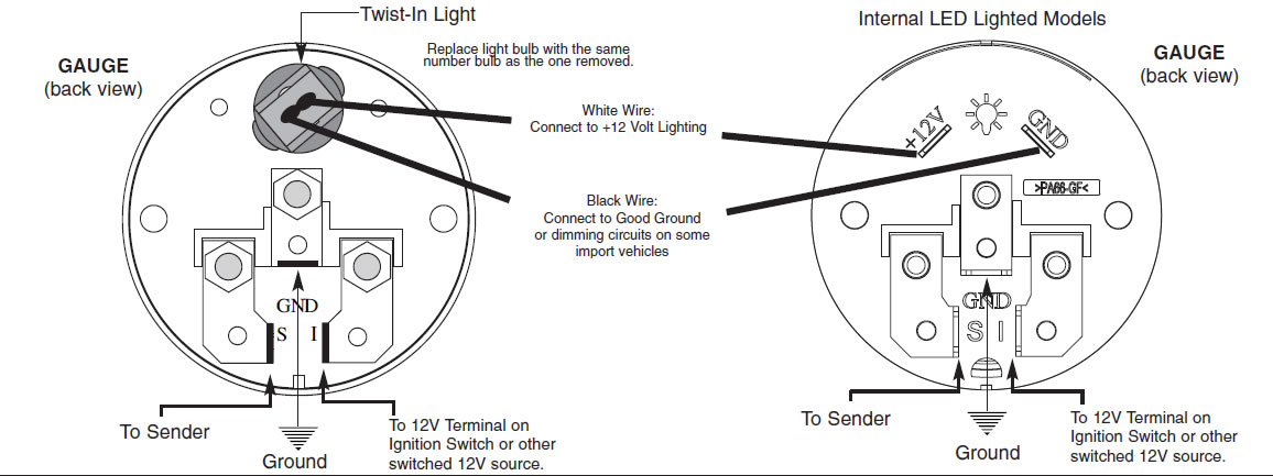
White Wire: Connect to +12 Volt Lighting. INSTALLATION INSTRUCTIONS. SHORT SWEEP ELECTRIC GAUGES. 2650-1079-00 Rev. C. Mounting. Replace light bulb with the same . number bulb as the one removed. These gauges can be mounted in-dash or in Auto Meter mounting solutions (panels, cups, pods, etc.). 2. 1 ⁄ 16" diameter gauges mount in 2. 1 ⁄ 16 ... Autometer Tach Wiring Diagram Auto Meter Sport P Electrical Drawing Rh G News Co on random diagrams, auto meter monster tach wiring diagram diagrams.A tachometer is a good addition to any vehicle equipped with a manual transmission. In my Jeep CJ-7, I didn't have one of those rare factory tachs so I chose the Autogage Tachometer /4 inch with an ...
Wiring Installation Instructions For Pyrometer Optional A Relay Gauge Controlled Output. Egt Exhaust Gas Temperature Gauge Westach Westberg Wiring Diagram. Digital Boost Vac Gauge Installation Instructions 2650 1236 00 Manualzz. 2 1 16 Pyrometer 0 1600 F Stepper Motor Sport Comp. Stealth 316 Autometer 3373 2 Channel Intake Air Temp.
Auto meter wire diagram
Connect this to the signal wire at your speed sender/sensor. If you are using a computer (ECM, PCM, ECU, etc), you may connect this to the factory speed signal wire at the computer instead of the speed sensor if it is equipped. Consult a diagram for your computer to verify. Blue: Oil PSI sender wire. Connect this to the Auto Meter oil pressure ... Autometer Basic Tach Installation Wiring Instructions Tutorial How-To http://www.jegs.com/webapp/wcs/stores/servlet/KeywordSearchCmd?manufacturer=Auto%20Mete... Autometer Sport Comp Tach Wiring Diagram. Wiring. The special design of the tachometer base allows for a variety of mounting For service send your product to Auto Meter in a well packed shipping carton. To operate the Sport-Comp Shift-Lite tachometer, first determine your desired. Sport-Comp Playback Tachometer · DPSS Shift-Light - Level 2 or ...
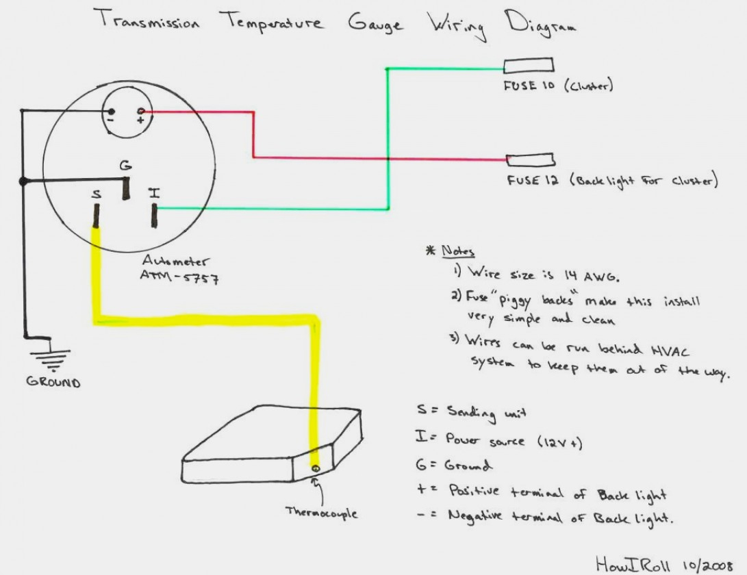
Auto meter wire diagram. How to Install an Auto Meter Pro-Comp Ultra-Lite Water Temp Gauge - Electric on Your Musta double check that all connections are tight. After starting engine, check wiring connections for hot spots. Be prepared to shut engine off immediately if hot spots are detected. Description: Autometer Gauges Wiring Diagram Autometer Oil Pressure Gauge throughout Autometer Temp Gauge Wiring Diagram, image size 514 X 387 px, and to view image details please click the image.. Here is a picture gallery about autometer temp gauge wiring diagram complete with the description of the image, please find the image you need. InVision Digital Dash. The best just got better with a new 4th screen for all InVision models! auto meter fuel gauge wiring diagram wiring diagram perfomance. Architectural wiring diagrams deed the approximate locations and interconnections of receptacles, lighting, and long-lasting electrical services in a building. Interconnecting wire routes may be shown approximately, where particular receptacles or fixtures must be on a common circuit.
Autometer Volt Gauge Wiring Diagram from www.bangshift.com Print the cabling diagram off and use highlighters in order to trace the routine. When you employ your finger or perhaps stick to the circuit along with your eyes, it is easy to mistrace the circuit. A single trick that I actually 2 to print a similar wiring diagram off twice. Pictured below is a copy of the wiring diagram for the Autometer Oil Pressure Gauge. To install an oil pressure gauge you will first need to purchase one. Pictured below is a copy of the wiring diagram for the Autometer Oil Pressure Gauge. left is labeled 'S', signal wire from oil pressure or water temp sensor? . Autometer Pro Comp Ultra Lite Wiring Diagram Fresh Auto Meter Wiring - Autometer Gauge Wiring Diagram. Wiring Diagram arrives with several easy to follow Wiring Diagram Guidelines. It's intended to aid all the average person in developing a suitable method. These guidelines will be easy to understand and apply. Wiring your new Autometer tachometer into your car will complete the installation. Once you have selected a mounting location, you can run the four wires that operate the tachometer. The tachometer is designed to show the engine RPMs or rotations per minute. Autometer has designed their tach to be used with four, six ...
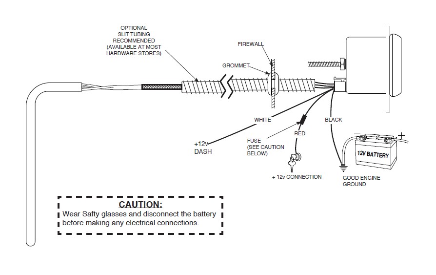
Autometer Tachometer Wiring Diagram - wiring diagram is a simplified gratifying pictorial representation of an electrical circuit. It shows the components of the circuit as simplified shapes, and the aptitude and signal connections between the devices. STEP 4. Run a length of wire from the temperature gauge to the sender unit using the wire supplied with the kit. Bare 1/4" of the end of the wire supplied at the sender unit. Install an eyelet terminal supplied with the kit on the end of the wire and crimp it tightly with a pair .Autometer Egt Wiring Diagram | Wiring LibraryAutometer Oil ... Recommended - Auto Meter Hall effect sender, 3-wire 16 pulses/revolution. 5291 Standard 7/8 - 18 thread 5292 Ford, plug in Mounting 1. 8Mount speedometer in a 33/ " dia. hole. Be careful not to cut the hole too large. 2. 8Cut a 3/ " dia. hole in the firewall for the speedometer wires. Place a rubber grommet in the hole and route Autometer Fuel Level Gauge Wiring Diagram - wiring diagram is a simplified all right pictorial representation of an electrical circuit. It shows the components of the circuit as simplified shapes, and the capability and signal friends between the devices.
Autometer Gauge Wiring Diagram | Wiring Diagram
3900 auto meter sport comp tach wiring diagram wiring library. Architectural wiring diagrams doing the approximate locations and interconnections of receptacles, lighting, and remaining electrical facilities in a building. Interconnecting wire routes may be shown approximately, where particular receptacles or fixtures must be upon a common circuit.
Auto Gauge Wiring
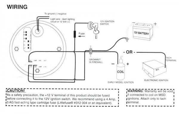
Autometer tach wiring diagram. For chrysler blue gold and silver. The wiring diagram shown is a typical installation. Figure a figure c. A wiring diagram is a simplified traditional pictorial depiction of an electrical circuit. The tach must be returned to autometer for a light replacement. Toll free tech support.

Autometer Sport Comp Wiring Diagram | Free Wiring Diagram
auto meter wiring diagram - What's Wiring Diagram? A wiring diagram is a kind of schematic which uses abstract pictorial symbols showing every one of the interconnections of components inside a system.
Auto Gauge Voltmeter Wiring Diagram - Wiring Diagram
auto meter wiring diagram - Exactly What's Wiring Diagram? A wiring diagram is a sort of schematic which utilizes abstract pictorial signs to reveal all the interconnections of parts in a system.

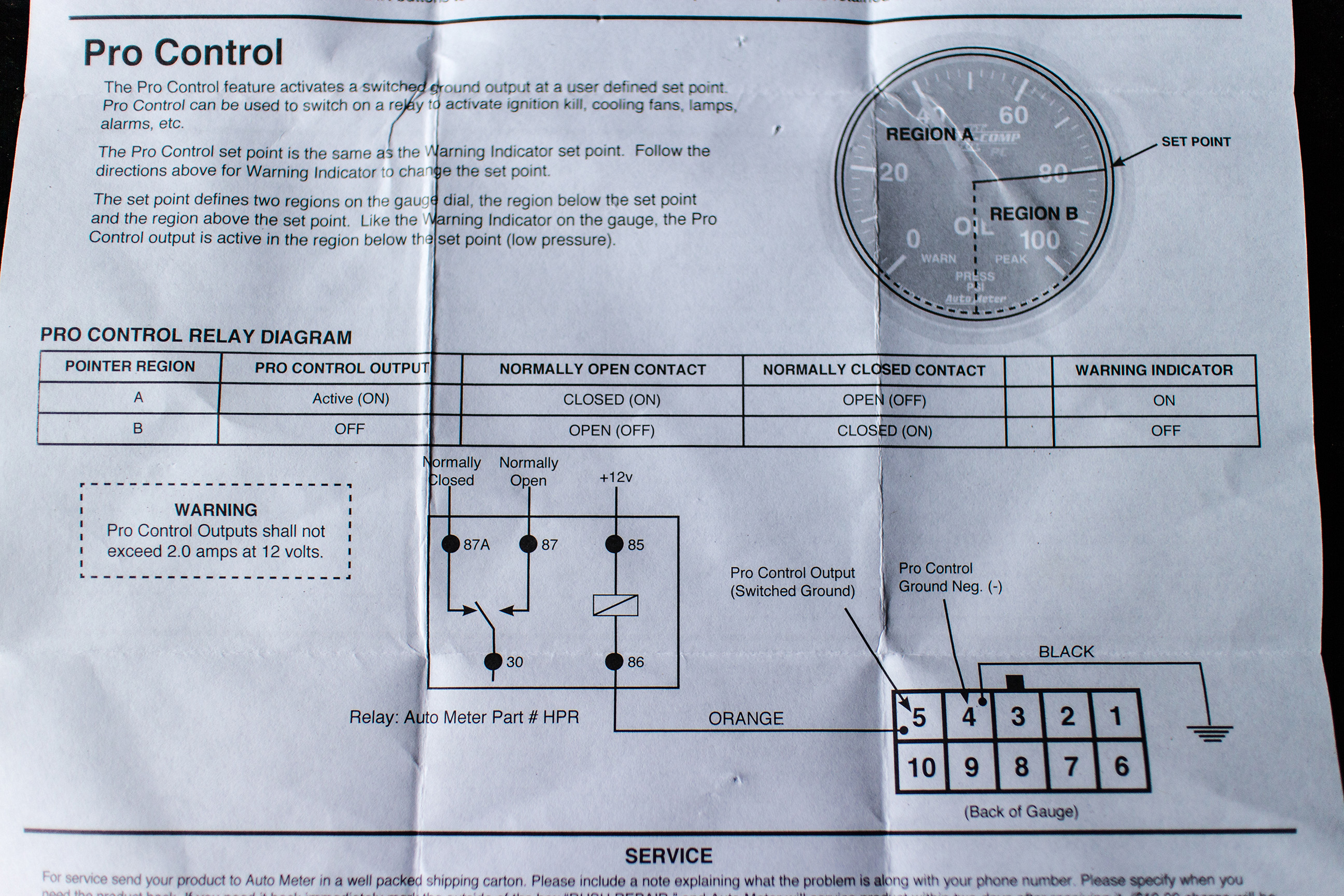
Autometer Oil Pressure Gauge Wiring Diagram
Recommended - Auto Meter Hall effect sender, 3-wire 16 pulses/revolution. Standard 7/8 - 18 thread 5292 Ford, plug in GPS Interface Module Universal Speed Sensor 3299 Optional Tach/Speedo Gauge Connector ... Wiring - Diagram 1 SIG Engine Dash Lighting Ground GND +12V GND LAMP OUT

Auto Gauge Tach Wiring Diagram Collection
Gauges. Autometer volt gauge wiring diagram how to install auto meter voltmeter mad with boat gauges instrumenteters classic style 60 160 vdc the hull truth boating cobalt air fuel ratio 3 ways a car amp electric monitor installation voltage instructions dimmer switch in direct fit 2 1 16 8 18v core wire on an tach images ford ranger tachometer electrical network short sweep panel 600a ammeter ...
![[DIAGRAM] Auto Gauge Wiring Diagram Oil Temp](https://blogger.googleusercontent.com/img/proxy/AVvXsEjae55gJi6IAqAxTLMd3UbdjVl5sQ4Bw-grUU6XXC6MemW2-7s8GjLHfZRXChSRktgrjDBVrMXpXcfkw-zyeP_377NtE8dJVzhudBb4e8Dj08f_HJV2S02kQ5MKT-hEEdkQ8xKkTv-o92vajgeOwdq_VDUv0Oj-2v7s-kjIkPyj5BecwLq8lKtxw_fbLQ=w1200-h630-p-k-no-nu)
[DIAGRAM] Auto Gauge Wiring Diagram Oil Temp
Auto Meter Products. 413 W Elm St. Sycamore, IL 60178. Toll Free Tech Support: 866.248.6357. Toll Free Customer Service: 866.248.6356. International: 815.895.8141
How to Install an Auto Meter Pro-Comp Ultra-Lite Water ...
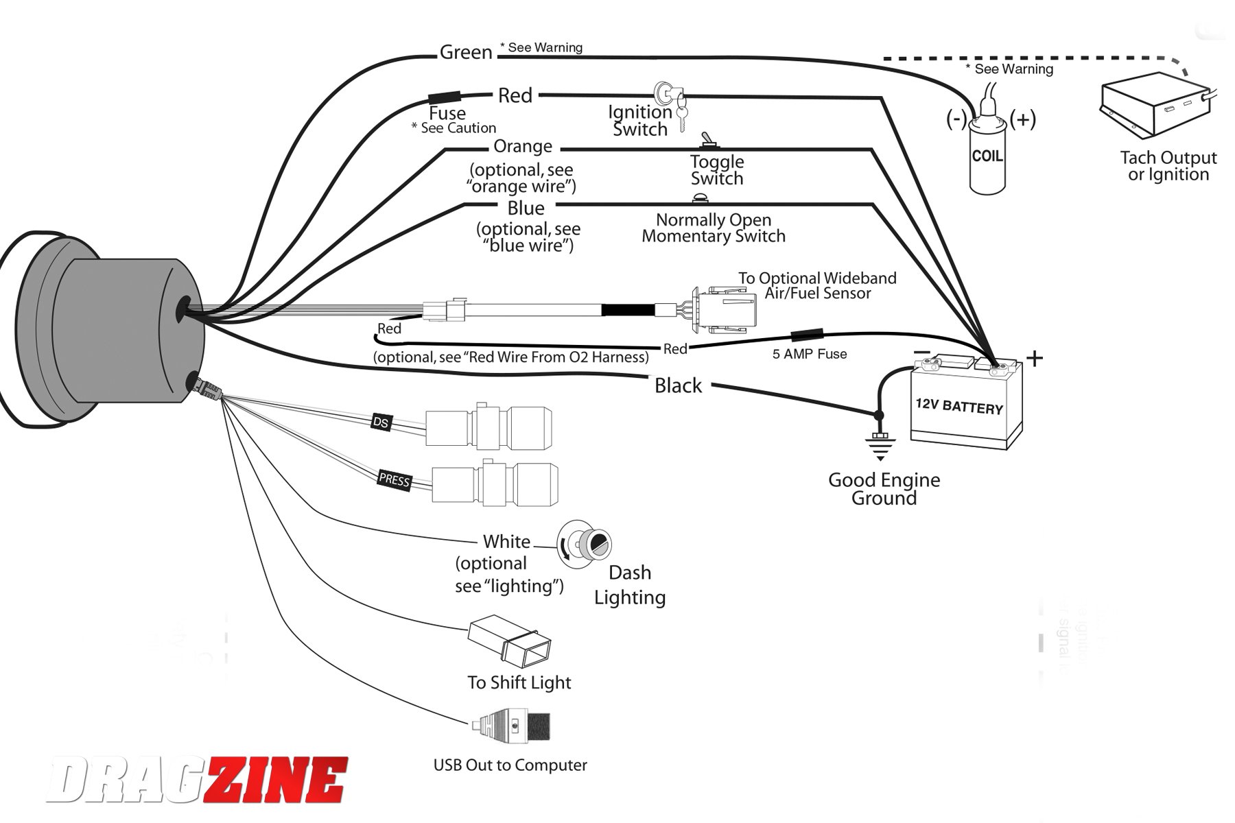
The wiring diagram. Wiring your new Autometer tachometer into your car will complete the installation. Once you have selected a mounting location, you can run the four wires that. Wiring. The special design of the tachometer base allows for a variety of mounting For service send your product to Auto Meter in a well packed shipping carton.
Autometer Voltmeter Wiring Diagram
오토 게이지 Autogauge Sm52 Voltmeter Black Face White Led With Warning 52 Pie 52avoswl270 Online In Vietnam 2001263923. Voltage gauge installation instructions how to install auto meter voltmeter 2 5 8 10 16v air core troubleshooting boat gauges 3 ways a car volt amp e wire on electric catalog proper operation stangnet vdo instruments classic style 60 160 vdc in wiring diagram autogauge ...

How to Wire An Ammeter and Shunt - YouTube
Auto meter electronic speedometer wiring diagram. Recommended auto meter hall effect sender 3 wire 16 pulses revolution. Hole in the firewall for the speedometer wires. See speedo senders below for available auto meter senders the speedometer should be calibrated to ensure accurate operation after installation. Secure wiring diagram 1 w typical.

Autometer Sport Comp Wiring Diagram | Free Wiring Diagram
autometer tach wiring wiring diagram technic Architectural wiring diagrams do something the approximate locations and interconnections of receptacles, lighting, and permanent electrical facilities in a building. Interconnecting wire routes may be shown approximately, where particular receptacles or fixtures must be on a common circuit.

Autometer Gps Speedometer Wiring Diagram | Free Wiring Diagram
Autometer Sport Comp Tach Wiring Diagram. Wiring. The special design of the tachometer base allows for a variety of mounting For service send your product to Auto Meter in a well packed shipping carton. To operate the Sport-Comp Shift-Lite tachometer, first determine your desired. Sport-Comp Playback Tachometer · DPSS Shift-Light - Level 2 or ...

30 Autometer Pyrometer Wiring Diagram - Wiring Diagram ...
Autometer Basic Tach Installation Wiring Instructions Tutorial How-To http://www.jegs.com/webapp/wcs/stores/servlet/KeywordSearchCmd?manufacturer=Auto%20Mete...

Autometer Gauge Wiring Diagram Short Sweep
Connect this to the signal wire at your speed sender/sensor. If you are using a computer (ECM, PCM, ECU, etc), you may connect this to the factory speed signal wire at the computer instead of the speed sensor if it is equipped. Consult a diagram for your computer to verify. Blue: Oil PSI sender wire. Connect this to the Auto Meter oil pressure ...
Autometer Pro Comp Tach Wiring Diagram Collection

Auto Gauge Tachometer Wiring Diagram Collection

Wiring Diagram For Autometer Gauges

Autometer Wideband Wiring Diagram

Auto Gauge Voltmeter Wiring Diagram - Wiring Diagram
How to Install Auto Meter Programmable Speedometer Gauge ...

Ar 5917 Wiring Diagram For Volt Meter
![[DIAGRAM] Gauge Auto Meter Speedometer Wiring Diagram FULL ...](https://2020cadillac.com/wp-content/uploads/2019/02/auto-meter-speedo-wiring-diagram-wiring-library-universal-fuel-gauge-wiring-diagram.jpg)
[DIAGRAM] Gauge Auto Meter Speedometer Wiring Diagram FULL ...

I want to wire in an ammeter to a 12v landrover

black Volkswagen Beetle beside beige wall
BangShift.com BangShift Tech: We Revamp Our Entire Dash ...

Tachometer Wiring Diagram - Wiring Diagram And Schematic ...

man refilling motor oil on car engine bay
Autometer Pro Comp Tach Wiring Diagram Collection
![[DIAGRAM] Auto Meter 9117 Tachometer Adapter Installation ...](https://static-cdn.imageservice.cloud/4235701/type-r-gauge-wire-diagram-everything-wiring-diagram.jpg)
[DIAGRAM] Auto Meter 9117 Tachometer Adapter Installation ...

Autometer Temp Gauge Wiring Diagram - Hanenhuusholli

Automotive Fuel Gauge Wiring Diagram Top Automotive Wiring ...

Automotive Voltmeter Wiring Diagram | AUTOMOTIVE

Find Out Here Autometer Gauge Wiring Diagram Download

Autometer Sport Comp Wiring Diagram | Free Wiring Diagram
autometer tach and msd 6AL box install | For A Bodies Only ...

man in white shirt and pants jumping on red car

Auto Gauge Speedometer Wiring Diagram - easywiring

Pin on bricolaje
0 Response to "38 auto meter wire diagram"
Post a Comment