40 airplane free body diagram
A general free-body diagram for steady level flight is presented in Figure 19-2. It is based on the dynamic diagram of Section 18.2.1, General two-dimensional free-body diagram for an aircraft, and Equations (18-1) and (18-2) (18-1) (18-2).
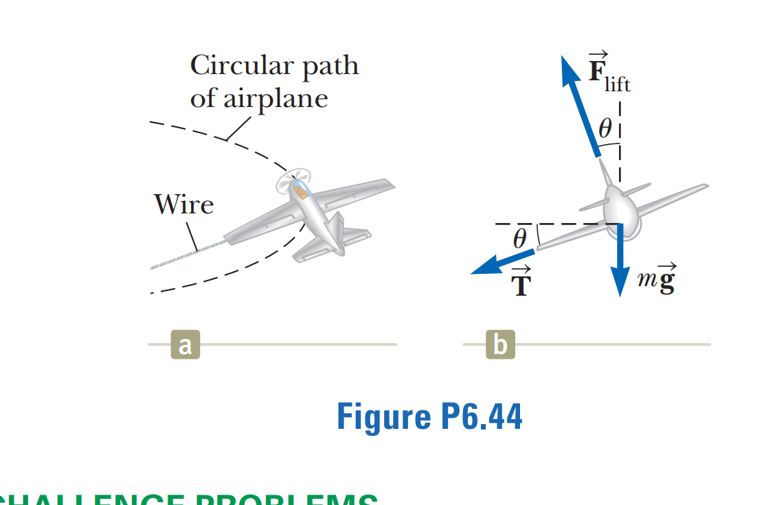
Free Body Diagram of an aircraft in a banked turn (1) As the aircraft banks the lift force normal to the wings is turned through an angle from the vertical weight vector. Since the centripetal acceleration acts horizontally and the weight acts vertically we can use simple trigonometric relations to find the radius of turn: such that .
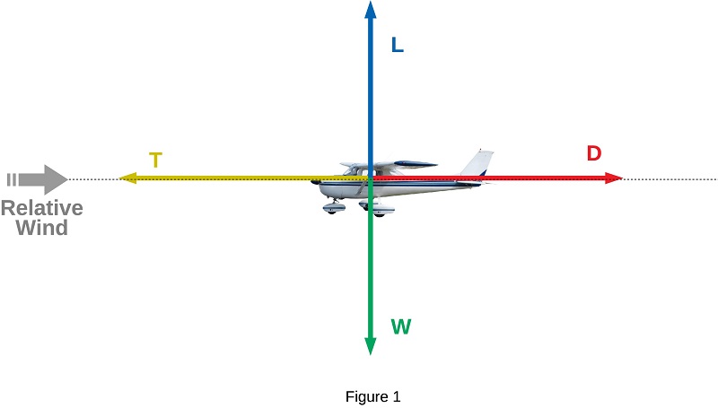
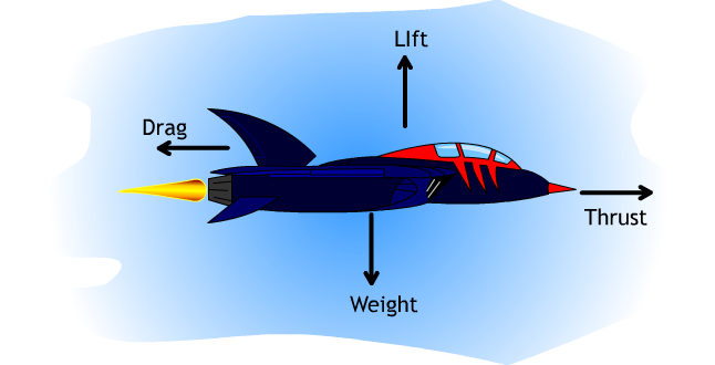
A force may be thought of as a push or pull in a specific direction. A force is a vector quantity so a force has both a magnitude and a direction. When describing forces, we have to specify both the magnitude and the direction.This slide shows the forces that act on an airplane in flight.. Weight Weight is a force that is always directed toward the center of the earth.

Airplane free body diagram
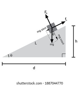
Solution a). Free Body Diagram The box is the small blue point. In the diagram below, W is the weight of the box, N the normal force exerted by the inclined plane on the box, F a is the force applied to have the box in equilibrium and F s the force of friction opposite F a. b) The box is at rest, hence its acceleration is equal to 0, therefore the sum of all forces acting on the box is equal ...
Solution. Figure 11.7 A solid cylinder rolls down an inclined plane from rest and undergoes slipping. The coordinate system has x in the direction down the inclined plane and y upward perpendicular to the plane. The free-body diagram shows the normal force, kinetic friction force, and the components of the weight.
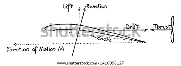
An airplane wing free body diagram illustrating forces acting on the wing. Keywords plane, planes, Aerodynamic of Aeroplane Wing, Airplane Wing Free Body Diagram, Aerodynamic Wing Free Body Diagram. Galleries Air Transportation. Source. H. Barber The Aeroplane Speaks (New York, NY: Robert M. McBride & Co, 1917)
Airplane free body diagram.
B) free body diagram of point P; three forces (upper part of figure below) 1) Tension T 1 2) Tension T 2 3) Tension T 3 Example 8 : A system with two blocks, an inclined plane and a pulley A) free body diagram for block m 1 (left of figure below) 1) The weight W 1 exerted by the earth on the box.
The Free-Body Diagrams for Inclined Planes Concept Builder challenges a learner to utilize an understanding of force types in order to construct a free-body diagram for an object moving along an inclined plane. Learners select force arrows from an arrow bank and label the arrows with a force type. There are 32 questions organized into 8 ...
In this tutorial, we will draw a free body diagram of an inclined plane with a load resting on top of it in LaTeX using TikZ package. We will draw a triangle to represent the inclined plane, a rectangle for the load, then add arrows with labels to highlight different forces. Table of Contents How to define a variable in LaTeX Draw a ramp in TikZ
Free-Body Diagram The sense of a force or couple moment ... the airplane fuselage A and wings B and C are located as shown. If these components have weights W. A = 225 kN, WB = 40 kN, and WC = 30 kN, determine the normal reactions of the wheels D, E, and F on the ground. 5-50
Draw a free-body diagram on a coordinate plane for this situation. [reveal-answer q="366612″]Show Solution[/reveal-answer] [hidden-answer a="366612″] [/hidden-answer] Additional Problems. Two small forces, N and . N, are exerted on a rogue asteroid by a pair of space tractors. (a) Find the net force.
The aircraft experiences a 9G upward load; knowing the data described above, one should be able to acquire the shear and bending moment distributions along the wing of the spitfire aircraft. STEP 1: Make a cut and draw a Free body diagram with all of the external forces acting on the body.
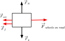
In a hypothetical situation without external forces (friction and air resistance), only the three remaining forces will act on the vehicle. A free body diagram is defined as an illustration that depicts all the forces acting on a body, along with vectors that are applied by it on the immediate environs.
Example - Aircraft Climb Performance Picture the Situation • Always picture the situation and sketch a free body diagram of the system • For this analysis we will ignore the second term in the Right Hand Side (RHS) of the differential equation (acceleration term) • This simulates that the pilot is interested in climbing as fast as possible
A free-body diagram of the object is shown in Figure 2. represents the tension in the string and the gravitational force on the object is where m is the object's mass and g is the acceleration due to gravity. Figure 1 Figure 2 The circular motion of the object is in the horizontal plane, so the horizontal
A free-body diagram is a diagram that is modified as the problem is solved. Normally, a free body diagram consists of the following components: The number of forces acting on a body depends on the specific problem and the assumptions made. Commonly, air resistance and friction are neglected.
Choose an appropriate free body diagram for the particle experiencing net acceleration along the negative y-direction. (Each arrow mark represents the force acting on the system). Answer: Question 7. A particle of mass m sliding on the smooth double inclined plane (shown in the figure) will experience _____.
Draw and label a vector diagram showing the direction of the centripetal force, velocity, and acceleration draw vectors on the star in the space below. Part II draw and label a free body diagram...
Statics
Free Body Diagram - 941 Words | Cram. Show More. Check Writing Quality. Register to read the introduction…. Move the ramp to an angle of zero (horizontal) and draw a free body diagram of the cabinet here: On a horizontal plane, the normal force is _Perpendicular_______ to the weight. The cabinet has a mass of 100kg.

Free body diagram of the aircraft during level flight ...
When a skydiver jumps out of a plane he starts accelerating downwards, until he reaches terminal speed. This is the speed at which the drag from air resistance exactly balances the force of gravity pulling him down. The figure below shows a free-body diagram of this. Where: g is the acceleration due to gravity, which is 9.8 m/s 2 m is his mass
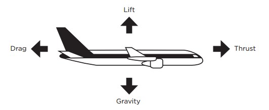
Four forces of flight - science world
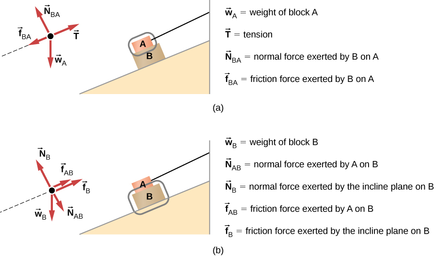
Figure 5.32 (a) The free-body diagram for isolated object A. (b) The free-body diagram for isolated object B. Comparing the two drawings, we see that friction acts in the opposite direction in the two figures. Because object A experiences a force that tends to pull it to the right, friction must act to the left. Because object B experiences a component of its weight that pulls it to the left ...
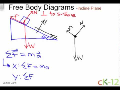
Fbd of an incline plane
This physics video tutorial explains how to draw free body diagrams for different situations particular those that involve constant velocity and constant acc...
Airplane wing free body diagram forces stock vector (royalty ...
A free-body diagram is a useful means of describing and analyzing all the forces that act on a body to determine equilibrium according to Newton's first law or acceleration according to Newton's second law. ... Draw a free-body diagram on a coordinate plane for this situation.

An aircraft is supported by the nose and main landing gears ...
Complete the free body diagram in Figure 2 to show the other two forces acting on the aircraft. Figure 2 (2) 1 (b)€€€€ A small aircraft accelerated down a runway at 4.0 m/s2 The aircraft started from rest and reached a speed of 34 m/s just before take-off. Calculate the distance the aircraft travelled while accelerating.

Physics reference: the force diagram shows an aircraft ...
Download scientific diagram | Free body diagram of a fixed-wing aircraft during a pitching maneuver. from publication: A MAV that flies like an airplane and hovers like a helicopter | Near-earth ...
Sph4c
Figure 1: Free body diagram of the idealized skydiver, a few seconds after jumping of the airplane. F D is the drag force, F w is the weight, m is the mass and g the acceleration due to gravity. F W = mg

Free-body diagram showing the forces acting on the ug in the ...
Drawing Free-Body Diagrams. Free-body diagrams are diagrams used to show the relative magnitude and direction of all forces acting upon an object in a given situation. A free-body diagram is a special example of the vector diagrams that were discussed in an earlier unit. These diagrams will be used throughout our study of physics.

Dylan stapp
When an airplane executes the vertical loop shown above, the centrifugal force causes the normal force (apparent weight) ... Free Body Diagram and Kinetic Diagram : Establish the r, q inertial coordinate system and draw the particle's free body diagram. = maq ma r mg N s N OA 2q.
Airplane wing free body diagram | clipart etc
Airplane Free-body diagram!! Homework Statement A plane with mass of 1090 kg is flying straight and level at an altitude of 1100 meters & a constant velocity of 200 kg/hr (55.55m/sec). Assuming that the acceleration due to gravity is 10 m/sec^2, the force on the plane due to gravity is 10900 Newtons.

Physics reference: the force diagram shows an aircraft ...
Simplified airplane motion
Solved can you show me how to solve for t based on this ...

Example problem

Free body diagram of a fixed-wing aircraft during a pitching ...
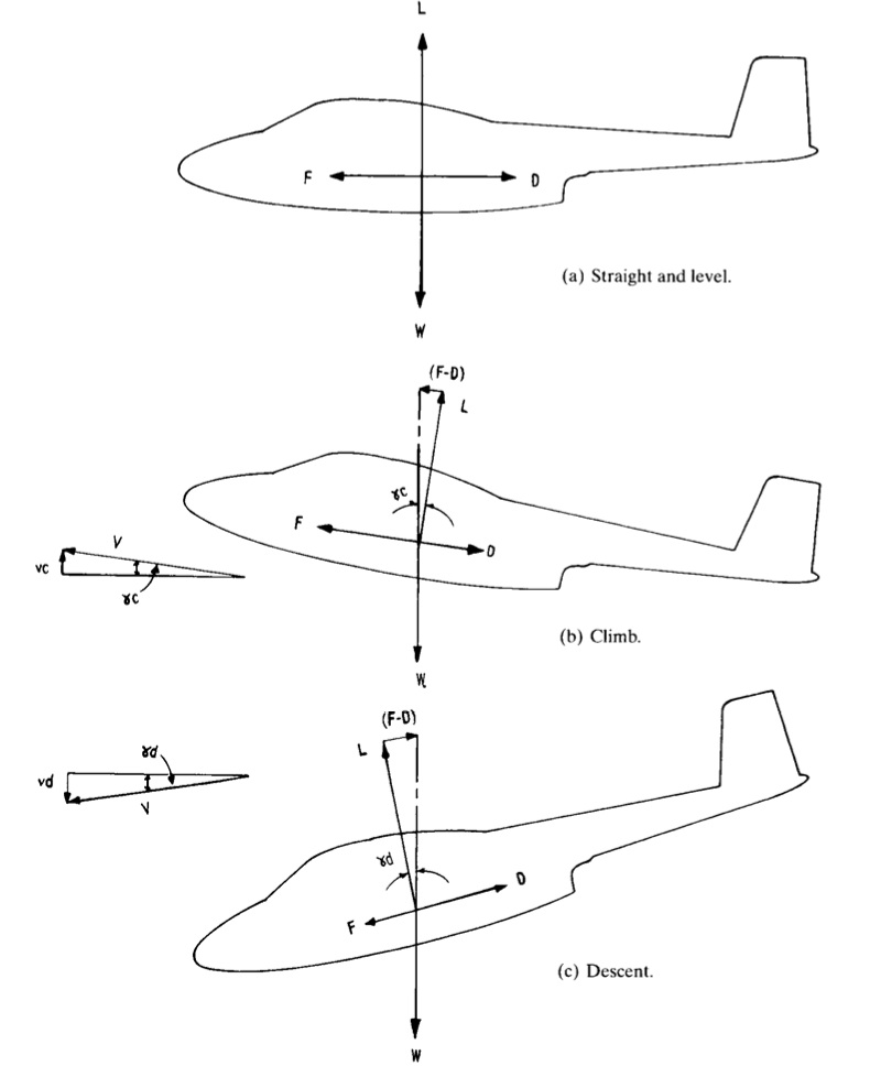
Is an airplane in a constant airspeed climb or descent in ...

Aircraft and treadmills | simple scientist
Loads acting on aircraft – aerospace engineering ...

Mr toogood physics - statics and forces in equilibrium
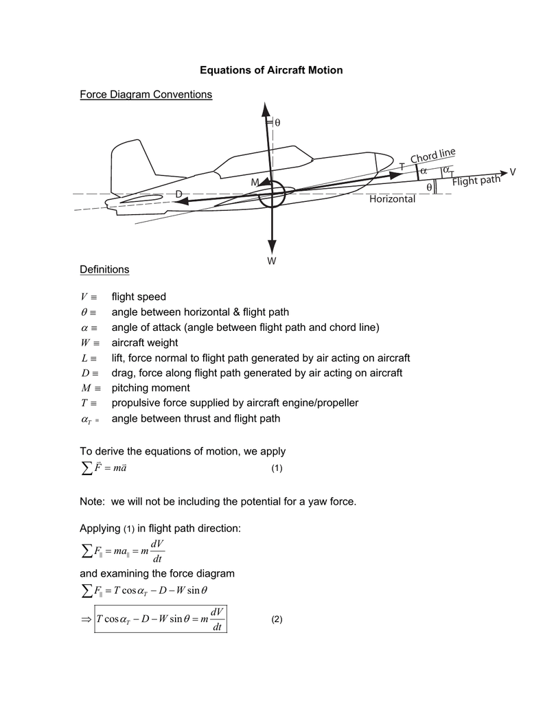
Equations of aircraft motion force diagram conventions ...
5.7 drawing free-body diagrams | university physics volume 1
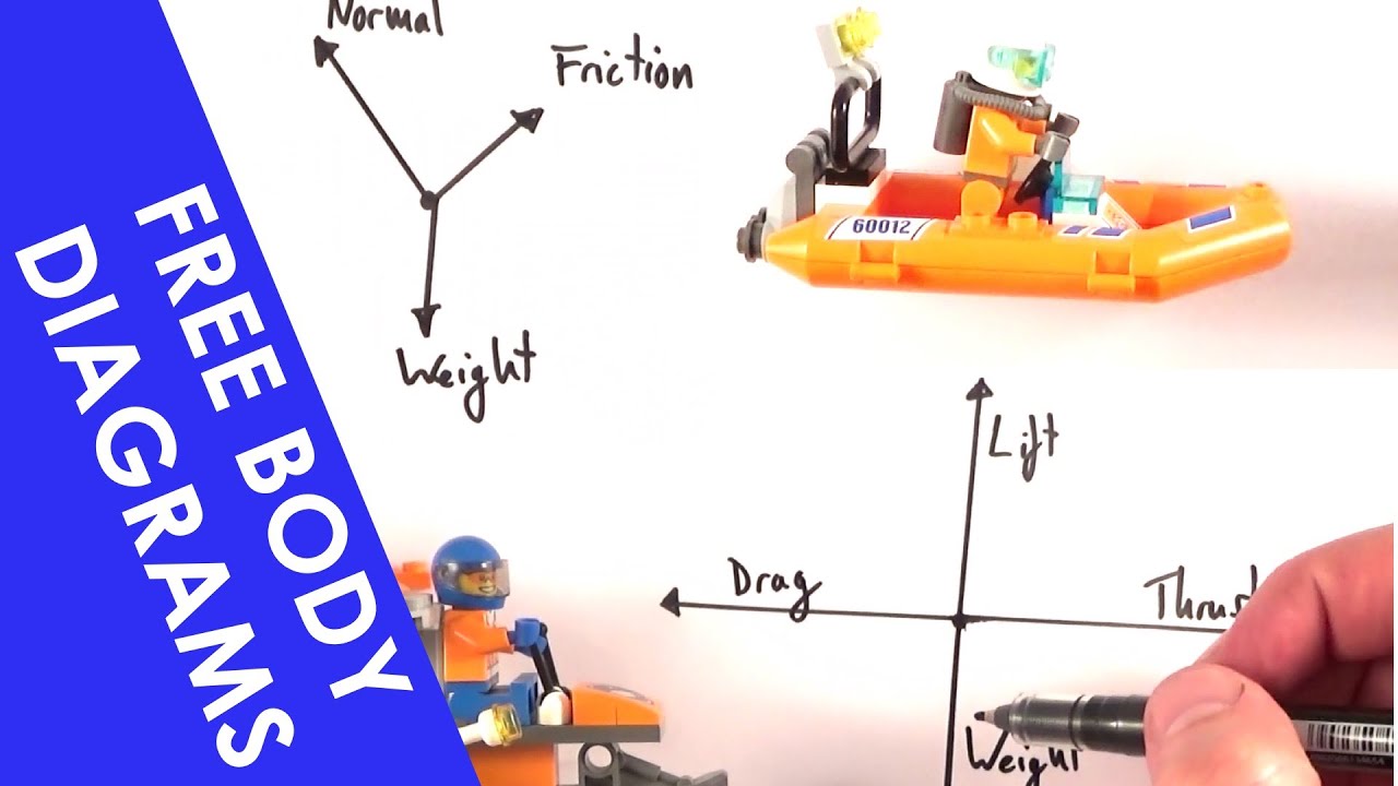
Free body diagrams ...basics
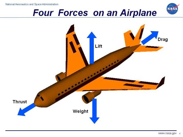
Forces on an airplane
Free body diagrams and objects on an inclined plane - a level physics

Every macroscopic and microscopic body or object in the ...
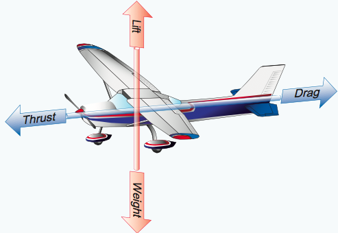
Forces of flight

Free-body diagram for a commercial aircraft on a planar ...

Example problem

Point mass force diagram for the longitudinal dynamics of the ...
Airplane free-body diagram | physics forums
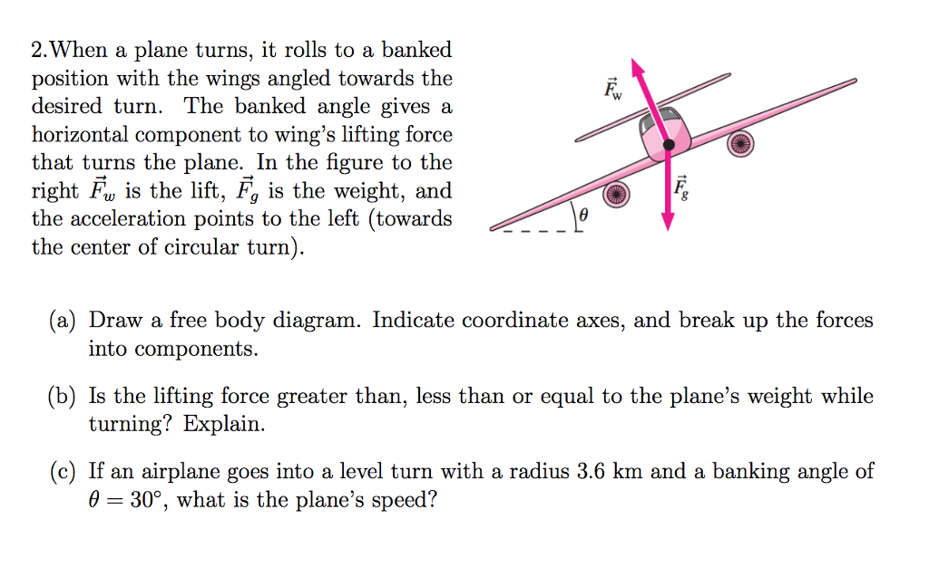
Solved 2.when a plane turns, it rolls to a banked position ...

Simplified free-body diagram of the aircraft. | download ...

Sf.2.a.b centre of gravity and forces | science - quizizz
Free body diagrams images, stock photos & vectors | shutterstock

Free body diagram - an overview | sciencedirect topics
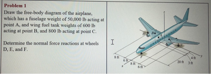
Solved problem 1 draw the free-body diagram of the airplane ...

Equilibrium at constant velocity

Loads acting on aircraft – aerospace engineering ...
0 Response to "40 airplane free body diagram"
Post a Comment