39 buzz coil wiring diagram
A wire is jumped terminal 86 to 87a. A wire is connected from terminal 30 to the battery positive. The condensor can be screwed onto the coil terminal, this mounts it and makes a connection, a wire is then run run to terminal 30. If you look at the diagram you will see that this is giving you a condensor across the relay points.
Hi; I have a little problem with your wiring diagram. On all the Bosch relays of this type that I have seen the 86 and 30 terminals are in ...7 Dec 2017 · Uploaded by doc0455
Check out our new channel "HisLifeHerWay'This is how to make a spark plug ignition buzz coil for your custom projects like pulse jets, hho, turbo jets, firew...
Buzz coil wiring diagram
Buzz Coil Wiring Diagram. By Margaret Byrd | September 11, 2018. 0 Comment. The petrolist diy how to make a buzzcoil old marine engine buzz coil magneto ignition for gas engines coils cenco and break joseph henry project cheap dependable msd blaster 2 wiring diagram needed nopistons mazda rx7 rx8 rotary forum shocking truth high voltage sparks tremble answer mystery device standing well back ...
Cap Wiring Diagram: View. Installation And Timing: View. Internal Coil Wiring Diagram: View. External Coil Wiring Diagram: View. Advance Kit Installation: View. Motorcycle Magnetos. Early Model Harley '74 Magneto Installation (#1274) ... Joe Hunt "Buzz Box" Timing Buzzer: View. Joe Hunt Battery Eliminator: View. Joe Hunt Universal Tach Converter:
How to Build It: Spark Plug Doing Its Thing. Putting this Buzz Coil together is as simple as following the wiring schematic. If you're using a socket for the relay, make the connections to the ...
Buzz coil wiring diagram.
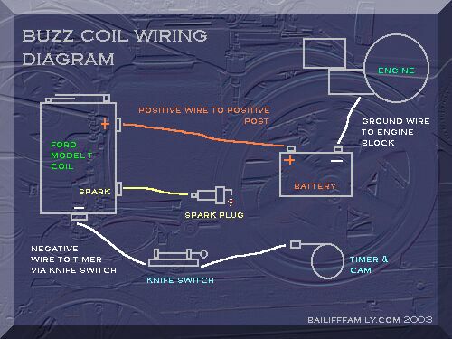
One wire to the engine spark plug, one wire to the engine timing (points) and one wire to ground on the engine frame. I even charged the battery so it will work right out of the box. In the Buzz Box is a refurbished set of Ford Model-T points, coil, condenser, on-off toggle switch, rechargeable 6 volt gel cell battery, and charging jack.
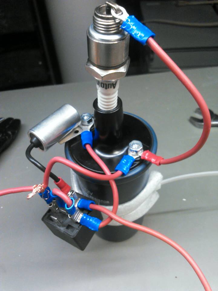
This is a buzz coil made from automotive parts. The coil is preferably an internal resistor type, ... The relays usually have a schematic on the cover.
Buzz Coil Wiring Diagram To properly read a electrical wiring diagram, one offers to find out how the components in the program operate. For example , when a module is usually powered up and it sends out a new signal of fifty percent the voltage in addition to the technician would not know this, he'd think he has a challenge, as this individual would expect the 12V signal.
Buzz Coil Flyback Hv Generator. The petrolist diy how to make a buzzcoil old marine engine buzz coil magneto ignition for gas engines cenco and break joseph henry project dew wiring diagram cheap dependable mystery device model t ford igntion restoration msd blaster 2 minimag co posts facebook forum testing box jump spark high voltage sparks solid state help me get it going flyback hv ...
Source: kmestc.com. Size: 250.14 KB. Dimension: 2050 x 1193. Assortment of simple ignition wiring diagram. Click on the image to enlarge, and then save it to your computer by right clicking on the image. Ignition Coil Wiring Diagram Gallery. Simple Ignition Wiring Diagram Best Great Lucas Ignition Switch.
Siemens S7 1500 Plc Wiring Diagram. Wiring and commissioning of the simatic s7 1500 and et 200mp systems. Clean beam s sole sourcing from siemens of the simatic s7 1500 software controller the simatic nanopanel ipc plus all the other core system components has simplified everything from procurement and licensing to programming and support.
Electronic buzzcoil installed on a 1/3rd scale model of a Hercules drag saw. Buzzcoil is enclosed in a scale sized "battery box" along with coil and sealed lead-acid battery, providing a self-contained ignition for operation at shows. Small size of the buzzcoil allows installation in tight areas, maintaining the scale appearance of your model.
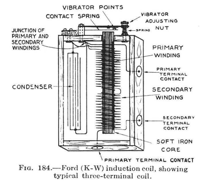
Buzz Coils: What to do if your coil decides to buzz off and the Buzz stops here. Ford, Jefferson, Pontiac, Kingston, Detroit and other buzzy boxes that made sparks (or were supposed to) back in the day. Buzz coils were used extensively on small engines for ignition of days gone by and by Henry Ford on the famous model T and Fordson tractor.
Apr 24, 2021 · Buzz coil wiring diagram. Round Twist Connector. Start the engine ( turn the key ) 3. Aug 02, 2018 · [Pin 4] Power (+) / ignition power: This is the main power supply for all of the coils, this power feed is activated when the key is turned to the "Ignition" position. Datasheet -production data Features • Smart electronic ...
K-W Ignition Company Magnetos. K-W is well known by Model T Ford owners for their ignition Buzz coils. For some years they were a manufacturer of ignition and lighting equipment.Here is a catalog of their product line from 1909. Their K-W model HK AKA the Highbar was used on early Holt crawlers and combines. When in repair they are very hot and ...
30 Mar 2015 — I decided to build a powerful, reliable, yet simple, buzzcoil. After browsing the internet for schematics without results, I stumbled upon ...
Buzz Coil Wiring Diagram For Hit And Miss. 12.01.2019 12.01.2019 0 Comments on Buzz Coil Wiring Diagram For Hit And Miss. Schematic for the Ford Model T buzz coil. Could someone tell me how to check a Ford Model T coil before I go through all the trouble of soldering some clips. Quick vid showing them Model T buzz coils in Action. Ford model T ignition coil - "Buzz" or "Trembler" coil ...
The shocking truth: how to make high-voltage sparks
Buzz Coil Wiring Diagram. Fuel Oil Furnace Schematic Diagram. Self Latching Relay Circuit Diagram. Schematic Diagrams Inverter Tbe 1500 Watt. Hive Wiring Diagram Worcester Greenstar 30si. Wiring Diagram Coleman Mach 15 Air Conditioner. Ps3 Controller Circuit Board Schematics.
Dew_wiring_diagram
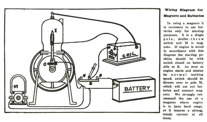
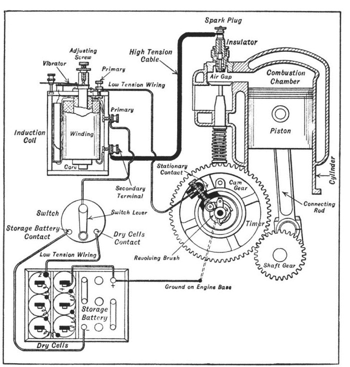
Note that the battery in the diagram can be either a battery or a low tension magneto. If you engine was not designed to run off a coil, then you need some ...

Gas engine buzz coil how-to - gas engine magazine | preserving the ...
sometimes if not working just dusty from sitting spray with electrical cleaner or just blow it out good.but sometimes you may have to take apat the top and c...

The petrolist: diy: how to make a buzzcoil
7 Jan 2020 — Learn how to make a simple, all-electronic buzz coil with David Cave as he ... (figure 3) Wiring schematic for the Evac 1 ignition coil.
Ignition types and coil wiring
Find your buzz coil wiring diagram/page/4 here for buzz coil wiring diagram/page/4 and you can print out. Search for buzz coil wiring diagram/page/4 here and subscribe to this site buzz coil wiring diagram/page/4 read more!

Gas engine buzz coil how-to - gas engine magazine | preserving the ...
How to wire a Model T Buzz Coil... Fun with high voltage
Magneto ignition for gas engines - buzz coils
See additional notes that follow in the summary section. You can make your own BUZZ COIL from easily obtained parts by visiting this link. This method using modern parts, has separate coils - one for stepping up the voltage to feed the spark plug and one to act as the "interrupter" changing the DC battery voltage to pulsating AC.
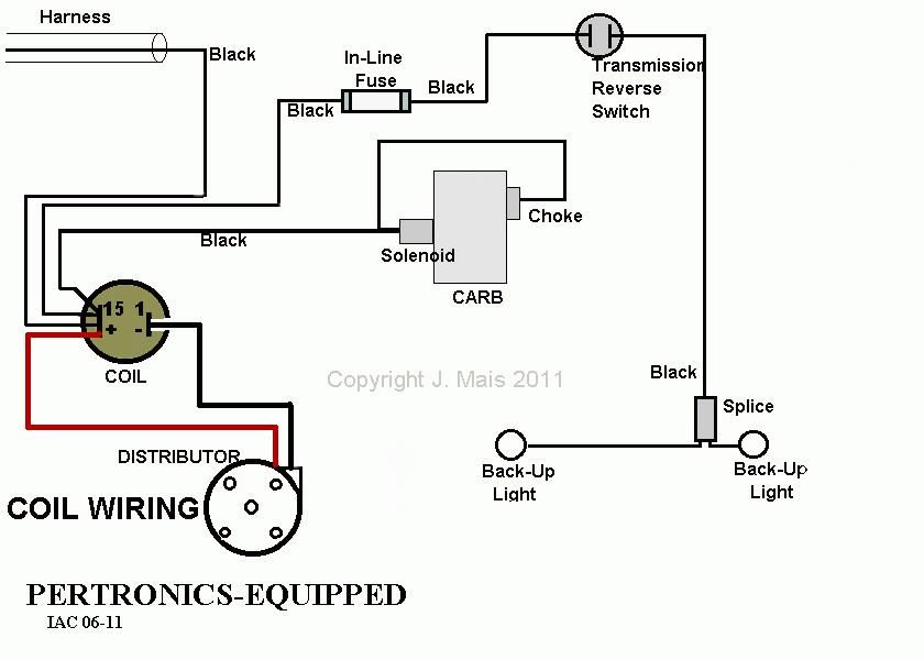
Coil wiring hook-up's - itinerant air-cooled
Description : Wiring Diagram For Ignition System Ignition System Wiring Diagram throughout Ignition Coil Wiring Diagram, image size 1146 X 344 px, and to view image details please click the image. Here is a picture gallery about ignition coil wiring diagram complete with the description of the image, please find the image you need.

Ignition coil wiring diagram | ignition coil, coil, vw super beetle
Initial offering will consist of ready-to-use Buzzcoil PC board assembly complete with pigtail leads. To complete installation just follow the wiring diagram using your model coil and battery. We suggest using the Exciter model coil and a miniature sealed lead-acid battery, both which are available through us if desired.

Solid state buzzcoil ignition
If you desire to build a buzz coil spark ignition system, then continue on. Note: A condenser from any automotive or small gas engine ignition system will work in the systems shown in the Image Gallery. Direction of hookup is not critical. For a buzz coil ignition system, start with a mounting board about 1/2″ x 3-1/2″ x 1/8″ to 1/4″ thick.
Engine buzz coil wiring | the tractor guys
Buzz Coil Wiring Diagram. By IOT | August 12, 2020. 0 Comment. The petrolist diy how to make a buzzcoil old marine engine buzz coil magneto ignition for gas engines coils cenco and break joseph henry project cheap dependable shocking truth high voltage sparks tremble answer mystery device standing well back model t ford igntion restoration adjustment dew wiring diagram circuit 2003 2007 v8 ...
Cenco make-and-break – joseph henry project
November 30, 2018 at 1:56 pm #157638. I assume you have a standard Model T buzz coil, with one power terminal on top, one on the bottom, and the spark plug terminal in the middle. Run one battery terminal (-) to the ground of the motor. Run the other battery terminal (+) to the top terminal of the coil. Then run a wire between the isolated ...
Old marine engine: a cheap dependable buzz coil
File Name : Model T Buzz Coil Wiring Diagram. File Size : 46391 Kb. We all know that reading Model T Buzz Coil Wiring Diagram is useful, because we are able to get enough detailed information online from the reading materials. Technology has developed, and reading Model T Buzz Coil Wiring Diagram books might be far more convenient and much easier.

How to make a buzz coil part 1
Once engine fires off, starter disengaged with ignition key now in Run position, current path pass through ballast resistor reducing voltage coil sees by about a third, or to around 8 volts. (depends on which ballast resistor being used) Locate your wiring diagram here, trace out both start & run circuits on a sheet of paper, then locate both ...

Model t ford forum: help me get it going!
Buzz coil wiring diagram. The signal on pin 9 controls the reset line pin 4 of the second timer and keeps the output at pin 5 is low while pin 4 and pin 8 is low and 12 high still open. External coil wiring diagram. Joe hunt battery eliminator. Joe hunt buzz box timing buzzer.

Vw distributor wiring diagram | wire, coil, ignition coil
The sound from a magnetic buzzer is produced by the movement of the ferromagnetic disk in a similar manner to how the cone in a speaker produces sound. A magnetic buzzer is a current driven device, but the power source is typically a voltage. The current through the coil is determined by the applied voltage and the impedance of the coil.
Microsquirt v3 coils
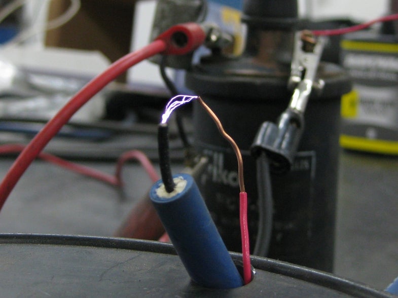
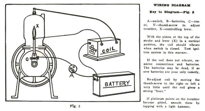
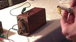
To test the coil, - FIRST rig a wire from the spark plug terminal to about 1/4" of the other top terminal. This will act as a safety spark gap. If you do not use a safety gap, the high voltage could arc inside the coil, ruining the insulation. - Connect the battery. The coil should make a buzzing sound and a blue spark should jump across the safety gap. If nothing at all happens and there is ...

Buzz coil condenser/capacitor | model engineer
Simplified Diagram of Model T Ignition Components v2.0 By Mitch Taylor Note: Colours for the timing wires changed for the 1926-27 models; these included coloured tracers. This diagram shows the correct colours up to 1925. SPARK (WIRES) TIMING (WIRES) GROUND (BODY) GROUND (WIRES) POSITIVE (BATT) COILS (POSITIVE) COILS 6 VOLT BATTERY FIRING ORDER ...

Model t ford forum: no coil buzz, 1919
picture of a diagram that detailed a proven method of wiring up a buzz coil and battery that should be capable of providing an operational ignition system for any single-cylinder rowboat motor, and here is a reproduction of that sketch to use for reference. Figure 1 - Sample Of Buzz Coil Wiring Diagram (courtesy of Jack Craib)
Magneto ignition for gas engines - buzz coils

Gas engine buzz coil how-to - gas engine magazine | preserving the ...

Homemade cop coil bench tester | december 08, 2016 | ratchet+wrench

Tremble! - the answer to the mystery device - standing well back
Cenco make-and-break – joseph henry project
Magneto ignition for gas engines - buzz coils

Buzz coil tester t model spark gap

Trembler coil - wikipedia
Old marine engine: buzz coil hookup
Buzz box wiring | antique outboard motor club,inc

Ford model-t buzz coil ignition | model t, ford models, ford
Model t ford igntion coil restoration and adjustment

Model t ford forum: cut-away coil
Ignition types and coil wiring

Ignition coil buzz box here's a circuit to create a buzzcoil using a ...
Ford model t ignition coil - "buzz" or "trembler" coil demonstration!

Getting fired up: completing the 1-1/4 hp baker monitor vj ...

Points condenser coil wiring unique | ignition coil, electrical ...
2az-fe ignition coil electrical harness clips - page 2 - camry ...
0 Response to "39 buzz coil wiring diagram"
Post a Comment