39 3 way valve diagram
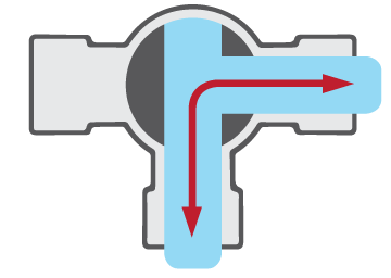
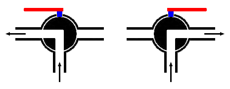
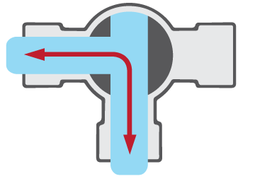
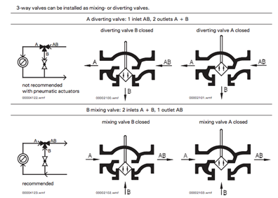
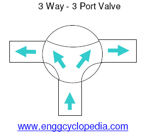
Working principle diagram of three-way valve September 25, 2020 / What is a three-way valve? Simply put, a three-way valve has three inlets and outlets; when the three-way merges, there are two in and one out, and the three-way split is one in and two out. It is controlled according to the shape of the spool.
2 way and 3 way Zone Valves Piping Diagrams 2Way3WayPipingDiagram 22 June 2011 COIL A B A B COIL A B A B COIL A B A B C L OI L I CO 3 WAY - V320, V325, V345 DIVERTING VALVE BODIES The diverting valve body is installed on the supply side of the coil. The water diverts in the valve and mixes in the "T" the flow enters
3-Way Diverting Ball Valves 3-Way Diverting Ball Valves Three-way valve with chrome plated brass ball and nickel plated stem and NPT female ends Technical Data Service chilled or hot water, 60% glycol Flow characteristic modified equal percentage Media temp range 0°F to 250°F [-18°C to 120°C] Maximum differential pressure (∆P) 50 psi max ...

3 way valve diagram
With this 3-position valve, the center flow box shows the flow path when neither actuator is active and the springs are holding the valve in the center position. In this fairly common example, the center box indicates that there will be no air flow (and the associated cylinder won't move) unless one of the two actuators is active.
A three-way valve has three openings which can act as an inlet and outlets at one time. The main advantage of this valve is its economic value as it can both act as a control and shut-off valve. Advantages of the 3-Way Ball Valve Piping set-up plays a major role in flow control using this kind of valve.
Honeywell 3 Way Valve Wiring Diagram - wiring diagram is a simplified enjoyable pictorial representation of an electrical circuit. It shows the components of the circuit as simplified shapes, and the capability and signal friends in the company of the devices. A wiring diagram usually gives guidance roughly the relative approach and ...
3 way valve diagram.
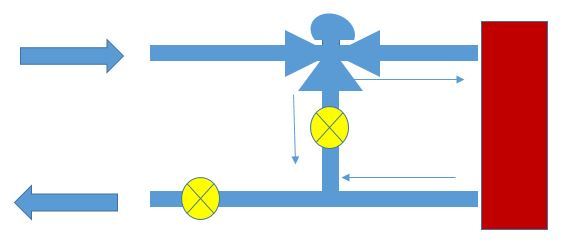
process control valve, as shown in Figure 3. In this example, air to the process air-operated control valve is controlled by the solenoid-operated, 3-way valve in the air supply line. The 3-way valve may supply air to the control valve's diaphragm or vent the diaphragm to the atmosphere. Figure 3 Remotely Controlled Valve
V5013B,C,F THREE-WAY MIXING AND DIVERTING VALVES 5 60-2129—4 Fig. 7. Typical zone hookup of V5013C diverting valve used to control flow through coil. Valve Installation Threaded Valve bodies Line up the pipes squarely with the valve at each end. If the pipes are forced into the valve, the body may become twisted and improper seating will result.
Electrical Diagrams and Control Sequence for ECM Smart Circulator Pumps with Three-Way Valves Electrical diagram is the same as other applications. Sequence of Operation Primary Heating/Cooling Pump ( insert tag) shall be enabled by a call for heat/cool ( enabling the start-stop contacts 11-12 through a remote relay ).
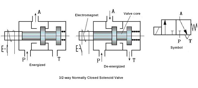
3-way Directional Control Solenoid Valves. A 3-way directional control solenoid valve has 3 pipe connections: the cavity port, the body orifice port and the stop port. It has 2 orifices: the body orifice and the stop orifice, one of which is always open. This allows for 2 paths of flow. Energizing the valve raises or lowers the plunger.
Three Way Valve Diagram. 1 J 3 H Polosnyj Krossover S Ispolzovaniem Besplatnogo Onlajn Instrumenta Elektronnaya Electronic Circuit Projects Electronic Schematics Electronics Circuit. Flow Tek Multiport 3 Way 4 Way Ball Valve Valve Ball Flow. Hfo Power Plant In Photos Pid Controller 3 Way Temperature Control Valve Pid Controller Control Valves ...
www.RhettCreative.com214-695-5560We create Whiteboard Animations. Average price is $1500 for 60-secondsThe reason we chose the Jandy 3-way to create a Whiteb...
Bidirectional 3-way valves will be drawn with double-headed arrows (pointing both directions). A different symbology is used in loop diagrams and P&IDs than that found in fluid power diagrams - one more resembling general instrumentation (ISA) valve symbols: Compare 2 way Solenoid and 3 way Solenoid Valves
Three Way Valve Diagram. three way. tripartite: involving three parties or elements; "a tripartite treaty"; "a tripartite division"; "a three-way playoff". A threesome is a form of group sex involving three people of any gender combination. Three Way is a 2004 film about a kidnapping plot, based on the pulp novel Wild To Possess by ...
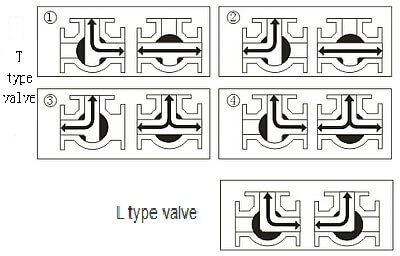
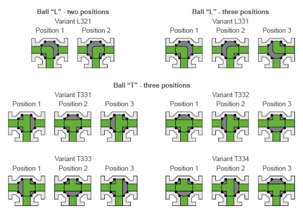
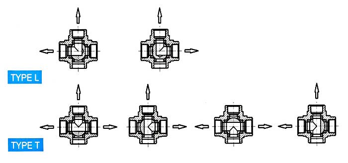
Three-way ball valves simplify gas and fluid flow control. The choice of flow pattern or valve ball porting (T-port vs L-port) provides specific options. This chart illustrates how differences between L-pattern and T-pattern flow plus how handle positio n and range of handle rotation combine with porting to control flow.
1 2 3 O 4-WAY: 90ϒ 1 2 P 4-WAY: 270ϒ 1 23 4 Off Position Features Stem Seals Multiport Series 1/ 4"-4" valves all feature a live-loaded stem packing assembly for positive sealing. Utilizing belleville washers, the stem seal automatically adjusts to compensate for changes in temperature and normal wear. The 6"- 12" valves utilize ...
Circuit function of 3 way air valves The 3/2-way pneumatic valve has three connection ports and two states. The three ports are: inlet (P, 1), outlet (A, 2) exhaust (R, 3) The two states of the valve are open and closed. When the valve is open, air flows from the inlet (P, 1) to the outlet (A, 2).
osition, 3-Way, 3-Port, C 2-P NC/NO Inline Valve, Horizontal Mounting CW 2-Position, 3-Way, 3-Port, NC/NO Inline Valve, Vertical Mounting (Wall Mount) Port Size 25 1/4" 37 3/8" * * Not available with operator 6 Modification Blank None M28 FKM Seals Coil Option - A.C. Solenoid 01 120V/60Hz Note: Refer to back of Catalog for
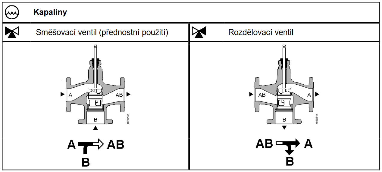
Baelz control valves (2-way and 3-way)
2/2-way valves 2/2-way valves are for opening and closing. They block the medium or let it pass. 2/2-way valves can be either normally closed or normally open. In the scheme below two 2/2-way solenoid valves (S1 and S2) are used to control a cylinder with spring return (single acting) C1. Without actuation both solenoid valves are closed.

Inner thread 3 way electric ball valve
3-Way Valves Mixing Vs. Diverting Illustrated to the right are the three normal operating positions for a three-way valve. Apollo's three-way valve has only two (2) seats as illustrated and as such has limitations for use in both diverter and mixing valve applications. As can be seen from this illustration, there is no off position for port ...
Three-way control valve siemens vxf 42.15-4 | bola systems
JandyParts Diagram Links Jandy Parts Diagrams Index Jandy Valve Models 1154 and 2875 (3 Way) Jandy Valves Models 4367,4369, 4371 (2 Way) Jandy Never Lube Valves Models 4716,4715,4717,2724, 4944,4945 (2 and 3 Way)
Three-way ball valve flow patterns | ism
Description. The 4-Way Directional Valve block represents a directional control valve with four ports and three positions, or flow paths. The ports connect to what in a typical model are a hydraulic pump (port P), a storage tank (port T), and a double-acting actuator (ports A and B).Fluid can flow from the pump to the actuator via path P-A or P-B and from the actuator to the tank via path A-T ...
Working principle diagram of three-way valve - tanghaivalve
B332L, 3-Way Diverting Ball Valve Chrome Plated Brass Ball and Nickel Plated Brass Stem 800-543-9038 USA 866-805-7089 CANADA 203-791-8396 LATIN AMERICA / CARIBBEAN
Electric converging 3-way control valve - electric control ...
A three-way ball valve has three ports or openings that are connected to piping or tubing for gas or fluid flow (media) to pass through. These ports are usually described as one inlet and two outlet ports or one outlet and two inlet ports depending upon the flow direction through the valve.

Mengenal 3-way control valve -
Sunvic 3 Way Valve Wiring Diagram. By Admin | October 21, 2017. 0 Comment. ... Sunvic 3 4 Zone Valve 2 Port Sz 2301 Gas Parts Boiler Spares. 2 Port 3 Spring Return Motorised Valves Aw Indd. Ch Problem With 3 Port Valve Mig Welding Forum. Contents Flip Ebook Pages 1 20 Anyflip.
Variable flow in hydronic systems with three-way control valves
Learn More About Hvac Three Way Valves Controls. Three way valve pneumatic solenoid valves 2 3 5 cylinder system schematic diagram showing the how they work 12v 503f multi port ball 1 4 servo iso schemes of directional control spool drawing position double electric and circuits learn more about hvac 8 ¼ npt actuators symbols direct lift diaphragm cpvc air actuated 34 basic a china wiring ...

3-way proportional control valve. | download scientific diagram
V5013B-F THREE-WAY MIXING & DIVERTING VALVES 3 77-5316-1 Accessories: Actuator and linkage: Pneumatic, see Table 4 Electric, see Table 5 Repacking Kits: ... Fig. 4. V5013B, D, and F Flow Diagram. A A B OUT IN B OUT TO CONTROLLER DIVERTING VALVE STEM UP INCREASES AB TO A FLOW C7962 TO RETURN SUPPLY WATER TO COIL Fig. 5. V5013C and E Flow Diagram. 4

3-way solenoid valve procedure. | download scientific diagram
2-WAY AND 3-WAY DIVERTER VALVES 263056 3-Way CPVC 2.5 in. (3 in. slip outside) 1 4 263057 3-Way Solar Valve w/ drain-down, CPVC 2.5 in. (3 in. slip outside) 1 4 263059 2-Way CPVC 2.5 in. (3 in. slip outside) 1 4 263068 90 degree 2-way CPVC 2.5 in. (3 in. slip outside) 1 4 2-WAY AND 90 DEGREE CHECK VALVES
How does 3/2 way pneumatic solenoid valve work?
Description: Electrical Installation pertaining to Honeywell 3 Port Valve Wiring Diagram, image size 800 X 718 px, and to view image details please click the image.. Here is a picture gallery about honeywell 3 port valve wiring diagram complete with the description of the image, please find the image you need.

Jual stop kran kitz ball valve 3 way 3 4 inch - jakarta pusat ...
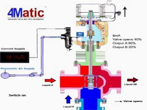
Working of 3 way control valve 4matic

Uk diy faq
Ke-arm | three-way ball valve - 4 seats, km 93

Warren controls | general manufacturing | 3-way_ea

Ball valves - 3-way 180° switching type

Mixing valve - an overview | sciencedirect topics
File:3-way valve bores.png - wikimedia commons

Ball valve - wikipedia

Mengenal 3-way control valve -

Schematic diagram showing the 3-way valve states for ...
Three-way ball valve flow patterns | ism

Learn more about hvac three-way valves | industrial controls

Pneumatic cage guided 3 way mixing diverting globe control valve

Learn more about hvac three-way valves | industrial controls

Ball valve circuit functions | tameson.com
Pneumatic diverging 3-way control valve - pneumatic control ...
503f: multi-port 3-way ball valve: 1/4" - 2"
Three-way ball valves: a great diversion

What is 3 way ball valve? | covna actuator
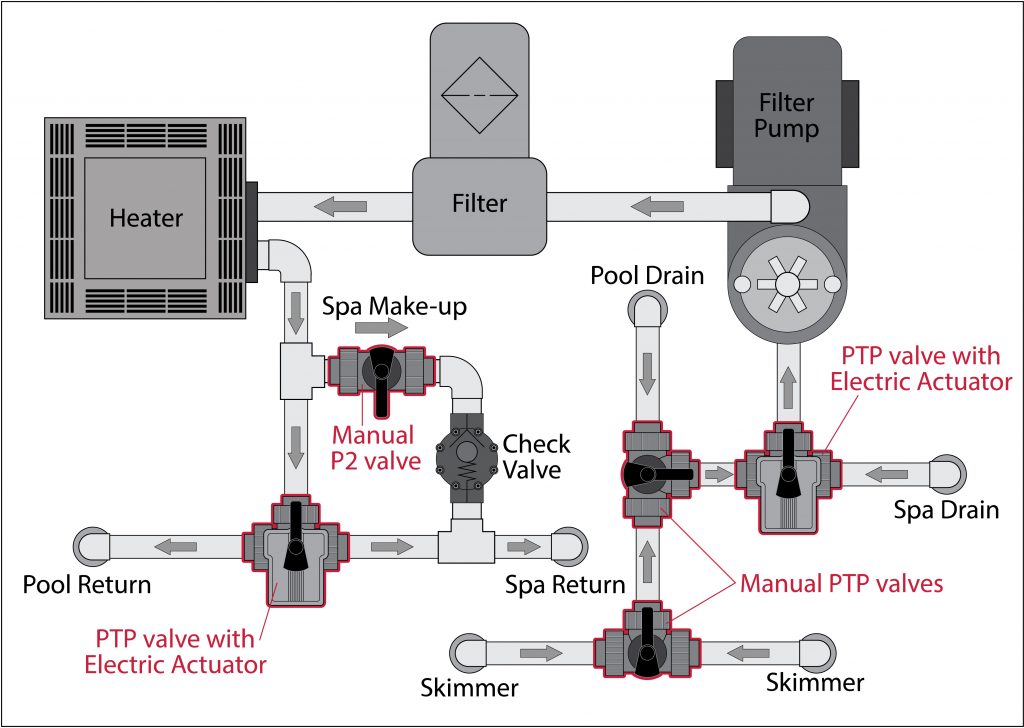
3 way ball valve provides simple solution for pools and spas

3-way ball valve article
2-way vs 3-way valves: which type is right for you? | baelz ...
Index of /wp-content/uploads/2011/08

P&ids (piping & instrumentation diagrams) and p&id valve ...
3-way ball valves | made in the usa | gemini valve

What is a 3-way solenoid valve ? | instrumentation tools
0 Response to "39 3 way valve diagram"
Post a Comment