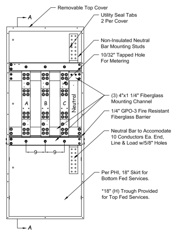
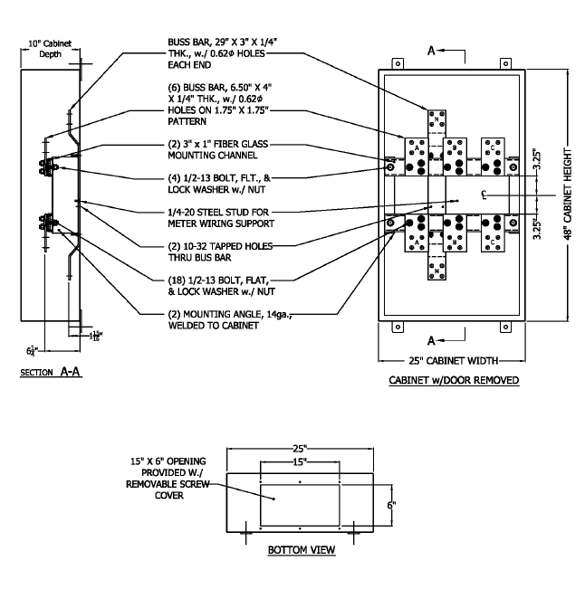
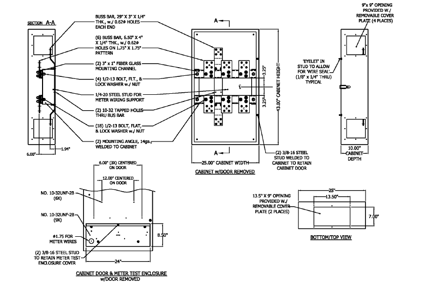
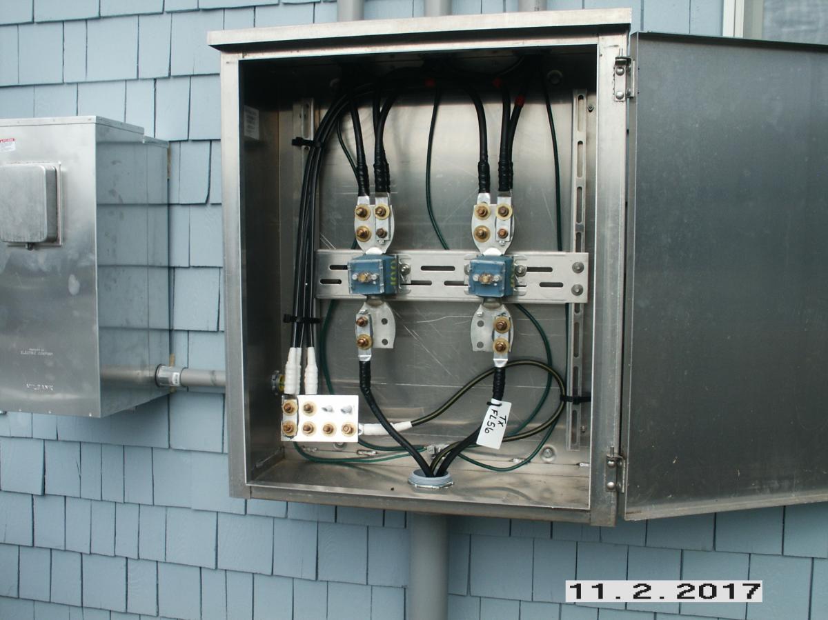
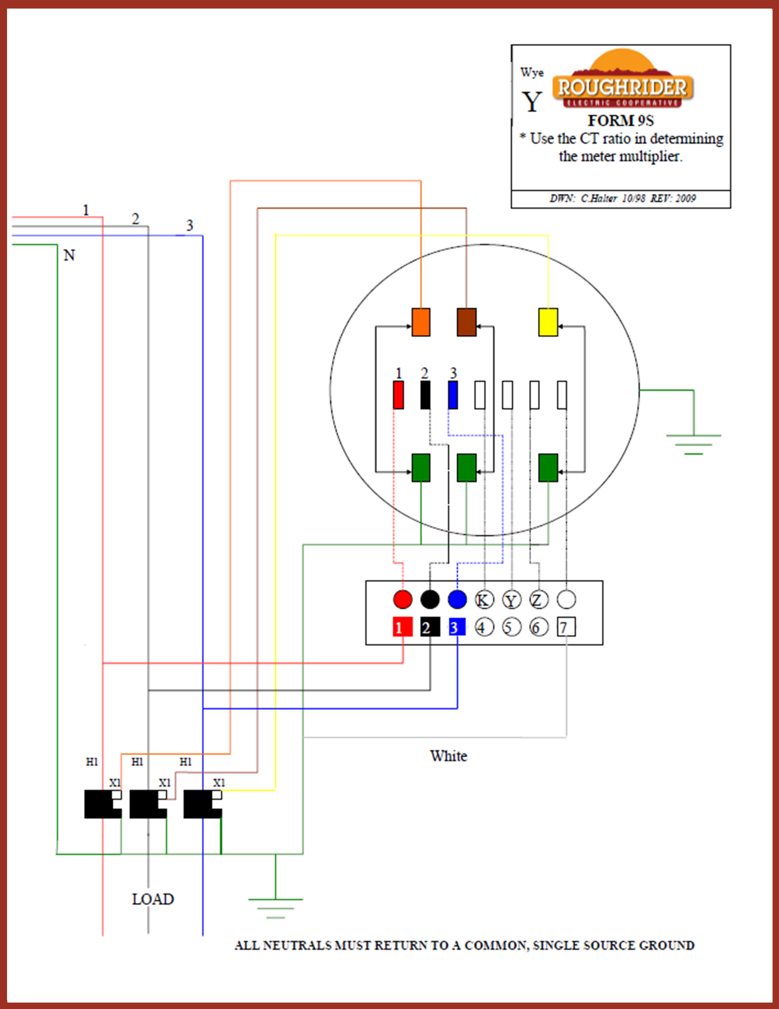
38 ct cabinet wiring diagram
WPSC SERVICE MANUAL. Revised 11/2020. Section 3 400 AMP AND LARGER - COMMON. Page 6 of 22. 3-3 UG CT Cabinets (Cont'd). Service Applications. Phase. Wire.22 pages
equipment assembly diagrams assigned to each installation by the DTE Electric ... installation converted to a CT-rated enclosure with a CT cabinet:.
CT cabinets feature & benefits . ... Transformer cabinets with factory-installed CT racks . ... Please be sure to provide a copy of your wiring diagram.

Ct cabinet wiring diagram
The Cooperative recommends that all work on the Member's facilities be performed by a qualified, licensed electrical contractor. CT/PT CABINET INSTALLATION FOR.1 page
22/10/2019 · Isolated Ground Receptacle Wiring Diagram: 241KB. 01/04/13: 70 Lighting E-70-01 (233KB) jpg Pole Base: 272KB. 06/27/12: E-70-02 (240KB) jpg Extended Pole Base: 272KB. 06/27/12: E-70-03 (176KB) jpg BSL3 Lab Lighting Installation: 279KB. 06/27/12: E-70-04 (194KB) jpg Typical Lighting Fixture Installation: 318KB. 06/27/12: 80 Miscellaneous E-80-01 (170KB) …
Google Images. The most comprehensive image search on the web.
Ct cabinet wiring diagram.
CT rated with test switch provision . ... Transformer cabinets with factory-installed CT racks . ... sure to provide a copy of your wiring diagram.48 pages
Apr 2017 - Teletype Wiring Diagrams - added scans of 28KSR/RO wiring diagrams 573-100-400TC Apr 2017 - Navy Teletype Manuals - added scans of 28KSR/RO manuals 0967-173-7010 and 0967-173-7020 Mar 2017 - Baudot-to-Morse converter - added photos of GNY-2206
TYPICAL GROUNDING/BONDING FOR CT CABINET AND GUTTER . ... METER SOCKET WIRING DIAGRAM 3-PHASE CLASS 320 AMP . ... Figure 13.1 CT Cabinet Installation .
wiring methods – Readily accessible as applied to installation ... • Riser Diagram • Floor Plan • Sequence of operation (matrix or narrative) • Equipment technical data sheets • Manufacturers published instructions Chapter 7 – Documentation Minimum Requirements • Battery calculations • Voltage drop calculations for NACs • Completed record of inspection and testing ...
... “S” Cabinet Installation – Notes and Bonding Diagram……………….………………………D29. Transformer Rated Meter Socket and Current Transformer Cabinet Installation…
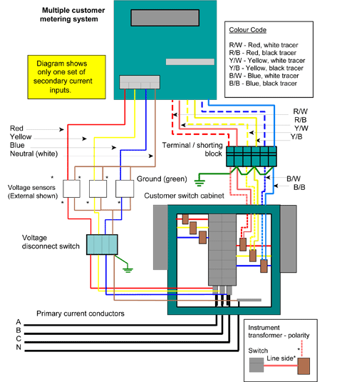
Page 5 of 41. 2.3 Wiring Diagram. A schematic diagram of the secondary circuits within a Lucy LV combined cut-out, CT & meter cabinet is as follows: ...
I want to split a 400 amp 3 ph. service into two- 200 amp feeds by ...

Electrical supply: electrical supply ct
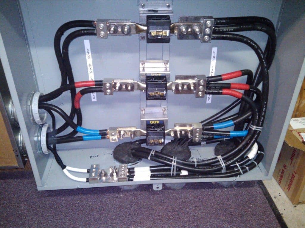
Ct cabinet, parallel bonding | electrician talk

Commercial guidelines & standards – central lincoln

8. metering pages 51 - 85 - flip pdf download | fliphtml5

Indoor hidroponik 600w tumbuh cahaya hps bohlam terbuka pemberat ...

Lt ac three phase, four wire panel mounted static kwh meter | manualzz

Service & main bonding jumpers

47 ways to wire your power meter wrong - kele.com
Ct cabinet wiring : r/electricians
P-e-04—generic procedures for conducting installation ...

Oliveri electric on twitter: "400 amp ct cabinet... http://t.co ...

Inspirational ge motor starter wiring diagram | washing machine ...
Ct electric meter wiring

Service entrance, 2phase, 3phase, service conductors, service ...

Electric service installation manual – alexander publications

New service/upgrades | pioneer electric cooperative
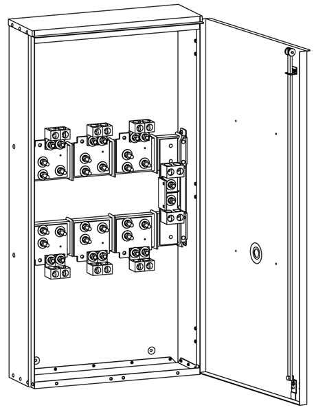
Current transformer cabinets: types, fabrication, uses | n.j. sullivan

Form 4s meter wiring diagram - learn metering
Current transformer cabinet - metering cabinet | n.j. sullivan

Current transformer metering | ct metering | overview | b-line ...

Wiring diagrams archives - learn metering
Pepco 400 to 800 amp nema 3r ct cabinet phict83 | n.j. sullivan
Multimeters | duquesne light company
Lt ac three phase, four wire panel mounted static kwh meter

8. metering - peco - an exelon company pages 51 - 84 - flip pdf ...

Commercial guidelines & standards – central lincoln
800 amp ct cabinet - mmi electrical contractors

Pin on electric golf cart
Current transformer cabinet 400a - 4000a wall mount on erickson ...
Pepco-400-to-800-amp-nema-1-ct-cabinet-phict81 | n.j. sullivan

Wiring new shop with 3 phase service - doityourself.com community ...

Ct cabinet with only 2 ct's in it - ecn electrical forums

How do ct chambers work? - ct chambers
Proud of this one. 600amp ct cabinet. : r/electricians
Electrical service upgrade: – his & her electric, llc
Resources for electricians | roughrider electric cooperative, inc
0 Response to "38 ct cabinet wiring diagram"
Post a Comment