36 pulley free body diagram
The pulley system for an elevator is shown in the figure on the left. This mechanical system consists of 5 pulleys and 2 electric motors. The maximum allowable ...
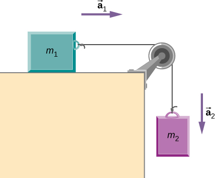
Using free body diagram as shown above, Block1: There is a tension force and frictional force in opposite directions. Fnet = T - friction => T = μ k *m 1 *g + m 1 *a. Block 2: There is an applied force towards the right. The tension and frictional force are acting in the same direction. Fnet = F - T - friction => T = F - μ k *m 2 *g ...
We can draw the free body diagram of bob at a as shown in figure 1.43. The force acting on the bob is it's weight mg and tension T of the string. Tenstion T is resolved in two components T cos θ and T sin θ as shown in figure 1.43. we can write the equation of motion. T cos θ = mg T sin θ = mv2/r.
Pulley free body diagram
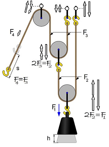
Free body diagram of the pulley system: The following analysis has been done for steady state (no acceleration )operation. The force on the driving pulley is equal to the difference of the two exerted tensions on each side. On one side, this force is equal to W e and on the other side, it is W c.
Free Body Diagram of Suspended Man The man is sliding across the rope on a bar and being pulled by the tension T. Ignore any frictional effects.
Free-Body Diagram Example Problem 3 Bank robbers have pushed a 1000 [kg] safe to a second-story floor-to-ceiling window. They plan to break the window, then lower the safe 4.0 [m] to their truck. Not being too clever, they stack up 600 [kg] of furniture, tie the rope between the safe and the furniture, and place the rope over a pulley.
Pulley free body diagram.
Pulley Free Body Diagram and rope tension armoredhalo00 Dec 28, 2010 Dec 28, 2010 #1 armoredhalo00 2 0 Homework Statement The figure above shows an 80 kilogram person standing on a 20 kilogram platform suspended by a rope passing over a stationary pulley that is free to rotate. The other end of the rope is held by the person.
To further test your understanding of free-body diagrams, see our force problems, which include problems where you need to draw free-body diagrams of objects that move up an incline, hang from ropes attached to the ceiling, and hang from ropes that run over pulleys. For each problem, we provide a step-by-step guide on how to solve it.
• Free body diagram for each element ... • Assume that the pulley is ideal -No mass and no friction -No slippage between cable and surface of cylinder (i.e., both move with same velocity) -Cable is in tension but does not stretch • Draw FBDs and write equations of motion
Is there any difference between the free body diagram of fixed pulley and movable pulley? Not particularly. The main thing is that you can assume the fixed pulley isn't accelerating, so all forces on it must sum to zero. A movable pulley may or may not be accelerating. is it true that fixed pulley has T1 and T2, but movable has T2 on both sides ...
Free-Body Diagram: Pulley C PROBLEM 2.69 A load Q is applied to the pulley C, which can roll on the cable ACB. The pulley is held in the position shown by a second cable CAD, which passes over the pulley A and supports a load P. Knowing that P = 750 N, determine (a) the tension in cable ACB, (b) the magnitude of load Q Hence: -O: TAcB(cos250 (750
Free Body Diagram Examples. Now we will explain the FBD concept, using the following free body diagram example problem as shown in Fig. 1. A 50 kg stationary box must be pulled up a 30 degree inclined by a pulley system.
figure 1 - pulley setup We have to draw one free-body diagram (FBD) for the hanging cylinder and another for the cart. 1. Each subject is represented by a dot (labeled with the mass) in Figures 2 and 3. - Figure 2 shows the FBD of the cart. - Figure 3 represents the FBD of the cylinder. 2. Forces are drawn and labeled on each object.
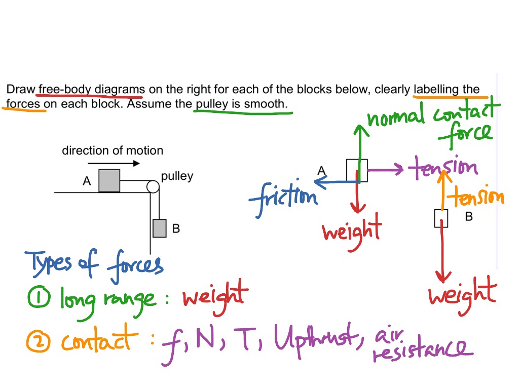
What would the free-body diagram of the balance of forces be for a rope and a pulley: a. For the rope turned 90 degrees? b. For the rope turned 180 degrees? 3. Experiment! Strings, Tension and Pulleys An ideal pulley is one that simply changes the direction of the tension. A man is holding a box at a constant height off the ground by means of a ...
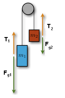
Using the pulley system illustrated to the right below as an example, the basic method for discussed. As in Lessons 15, 16 and 17, the basic method is to draw a free body diagram of the forces involved, write an expression for the net force, and then solve for the acceleration. In a pulley system two masses are strung over a pulley. Note that ...
B) free body diagram of point P; three forces (upper part of figure below) 1) Tension T 1 2) Tension T 2 3) Tension T 3 Example 8 : A system with two blocks, an inclined plane and a pulley A) free body diagram for block m 1 (left of figure below) 1) The weight W 1 exerted by the earth on the box.
Making accurate free body diagrams for a system of blocks connected by string and pulleys is an important step towards writing the correct equations of motio...
Also, let the magnitude of accelerations be “a”. Static pulley system. Free body diagram of body of mass 10 kg.
Pulleys
From the perspective of a free-body diagram the compound pulley system could be replaced by tying two ropes to the load and pulling up on each with a force equal to the effort. The disadvantages of pulleys, in contrast to machines that use rigid objects to transfer force, are slipping and stretching.
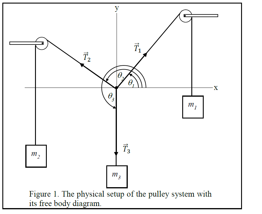
Solved 2 3 figure 1. the physical setup of the pulley system ...
free-body-diagrams. T From the above discussions, we have the three equations: This is less than that in case 1 as we predicted. 9. Atwood's machine. Atwood's machine involves one pulley, and two objects connected by a string that passes over the pulley. In general, the two objects have different masses. a a. 10. Re-analyzing the Atwood's ...

Determining tension and free body diagrams for a three-stage ...
Stack Exchange network consists of 178 Q&A communities including Stack Overflow, the largest, most trusted online community for developers to learn, share their knowledge, and build their careers.. Visit Stack Exchange
Multiple forces acting on an object | studypug
Remember that a free-body diagram must only include the external forces acting on the body of ... A light rope is attached to it and runs over a pulley.Newton’s second law, vector form: →Fnet=∑...Net external force: →Fnet=∑→F=→F1+→F2+...Definition of weight, vector form: →w=m→gw...Newton’s second law, component form: ∑→Fx...

A free-body diagram that is typical of what is found in ...
Free-body diagram with pulley. An object with a mass M = 250 g is at rest on a plane that makes an. angle θ = 30º above the horizontal. The coefficient of kinetic friction between M and the plane is µk = 0.100. Mass M is attached by a string to another mass, m = 300 g, which hangs freely. When mass m has fallen 30.0 cm, its speed is?

Physics 4.8 free body diagrams (2 of 10) the atwood machine ...
Pulley1 pulley2 do a free body diagram on pulley 2. The free body diagram below shows the weight w and the tension t1 acting on the block. No thanks try it free. This points into the page which is the negative direction. Draw a fbd of bar ac. The word body is used to describe any object. Tension t2 acting on the ceiling and fc the reaction to t2.

Free-body diagram of wheel 1, wheel 2, the pulley and the ...
http://www.physicshelp.caGO AHEAD and click on this site...it wont hurt.Free simple easy to follow videos all organized on our website
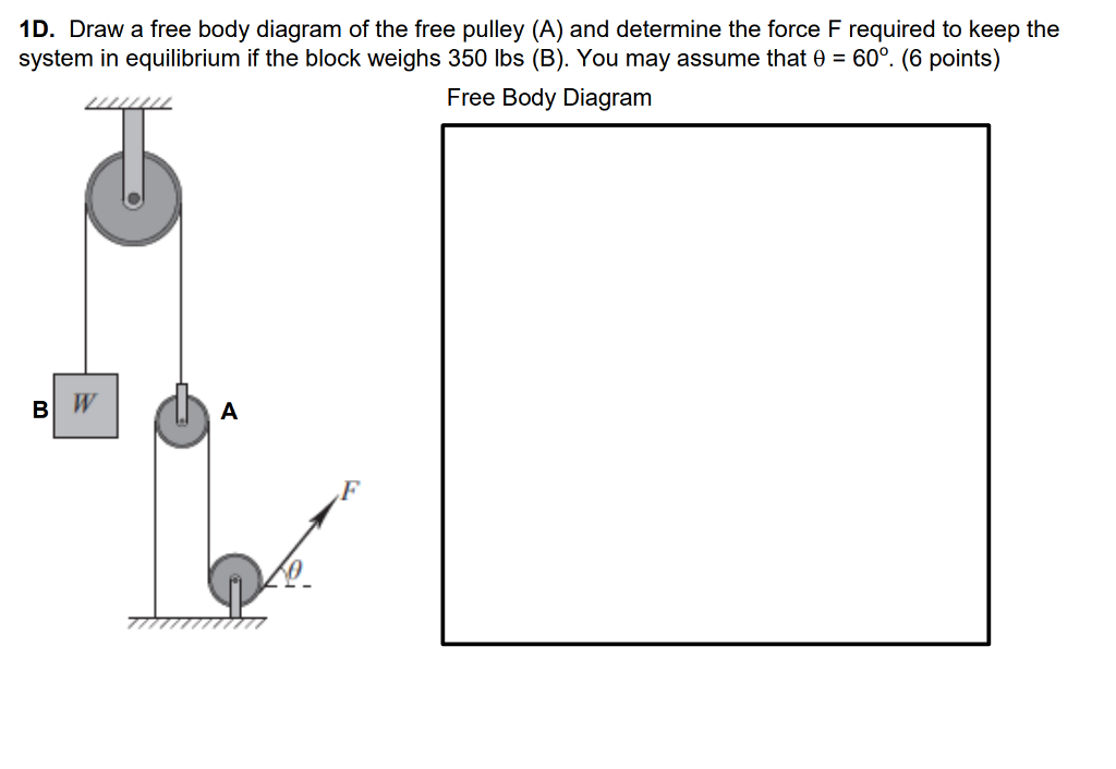
Solved 1d. draw a free body diagram of the free pulley (a ...
For each object, draw a free-body diagram, ... An upward force of 25N is applied to the pulley. Assume massless cord and pulley, and no friction.19 pages

Free body diagram (how do you make free body diagrams?) #6
Figure 5.6: A diagram for the system of two objects and a pulley. Figure 5.7: Free-body diagrams if there is no friction. (a) The free-body diagram of the red box. (b) An appropriate coordinate system for the red box. (c) The free-body diagram of the red box, with force components aligned with the coordinate system. (d) and (e), a
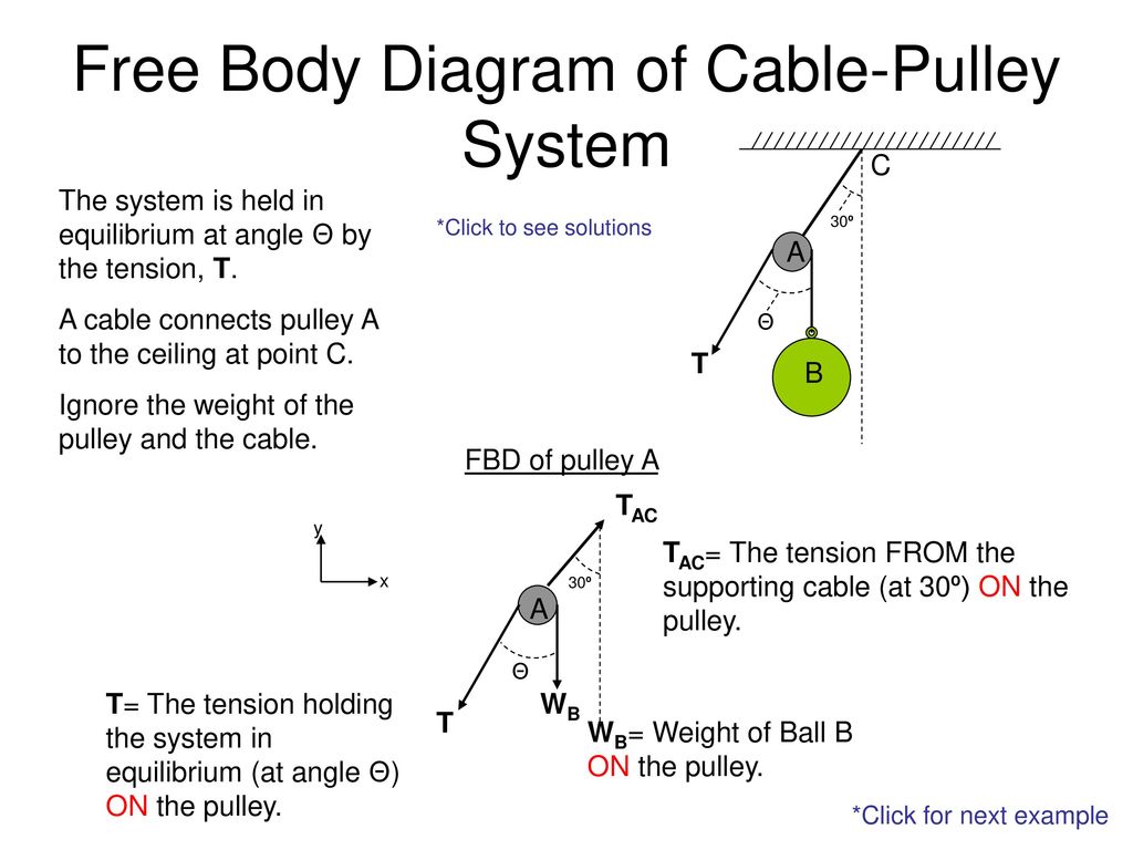
Free body diagram of cable-pulley system - ppt download
Step 2 - Draw a free-body diagram of the pulley. A complete free-body diagram of the pulley, shown in Figure 11.3 (a), reflects that fact that the center-of-mass of the pulley remains at rest, so the net force must be zero. There is still a non-zero net torque, about an axis through the center of the pulley and perpendicular to the page,

Example 10
FREE-BODY DIAGRAMS (Section 5.2) 2. Show all the external forces and couple moments. These typically include: a) applied loads, b) support reactions, and, c) the weight of the body. Idealized model Free-body diagram (FBD) 1. Draw an outlined shape. Imagine the body to be isolated or cut "free" from its constraints and draw its outlined shape.

Free-body diagram of the pulley and the associated vector ...
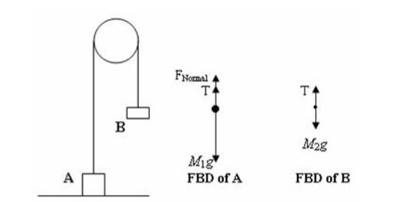
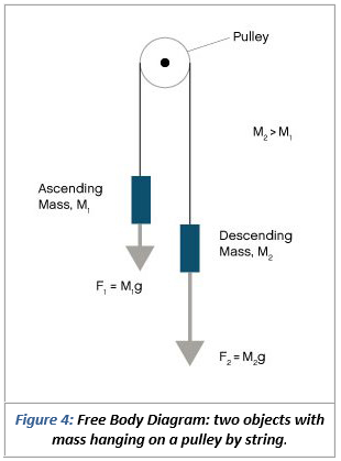
placed over a pulley as indicated in the diagram below. There are TWO free-body diagrams since there are two masses in this problem. M 1 M 2 Pulley X Y W 1 T 1 W 2 T 2 Free-Body Diagram for M 1 Free-Body Diagram for M 2 i) W 1 is the force of gravity on mass M 1 and W 2 is the force of gravity on mass M 2. W 1 = M 1 g and W 2 =M 2 g. ii) T 1 is ...
File:power pulley fbd.jpg - wikimedia commons
Download scientific diagram | Free-body diagram of the pulley and the associated vector configuration. from publication: Tension analysis of a ...
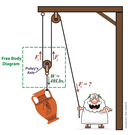
Free body diagram | engineering expert witness blog
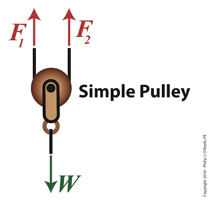
Free body diagrams. The mechanical advantage of a pulley system can be analysed using free body diagrams which balance the tension force in the rope with the force of gravity on the load. In an ideal system, the massless and frictionless pulleys do not dissipate energy and allow for a change of direction of a rope that does not stretch or wear.
Free body diagram for pulley
Boddeker 131 Ch 5 Homework. Ch 5 pulley. Two objects are connected by a light string that passes over a frictionless pulley. (a) Draw free-body diagrams of both objects. If the incline is frictionless and if m1 = 5.00 kg, m2 = 10.00 kg, and q = 60.0°, find (b) the accelerations of the objects, (c) the tension in the string, and (d) the speed ...

Pulleys - physics for k-12 - openstax cnx
Several problems with solutions and detailed explanations on systems with strings, pulleys and inclined planes are presented. Free body diagrams of forces, forces expressed by their components and Newton's laws are used to solve these problems. Problems involving forces of friction and tension of strings and ropes are also included.. Problem 1

Free-body diagram of the pulley and the associated vector ...
The free-body diagrams for the two objects are shown below. Because the parallel component of gravity on m 1 exceeds the sum of the force of gravity on m 2 and the force of friction, the mass on the inclined plane (m 1 ) will accelerate down it and the hanging mass (m 2 ) will accelerate upward.
Solved use the free body diagram of the pulley (figure 4) to ...

Elevator 1 » my favorite tutor
Sharetechnote
Help with free body diagram | physics forums

Free-body diagram for the lower pulley. the lower pulley has ...

Free body pulley 2
Interaction between an ideal pulley and an ideal rope ...
Drawing free body diagrams of boxes linked by strings over a ...
Lesson 10.2 - gns physics 11
Dua buah balok bermassa m1 dan m2 diikat dengan tali bermassa ...
5.7 drawing free-body diagrams | university physics volume 1

Free body diagrams free body diagram visual representation

Free body diagrams for any complicated situation, isolate each object;
Using a free body diagram to understand simple pulleys ...

Part 4
Two-body problems
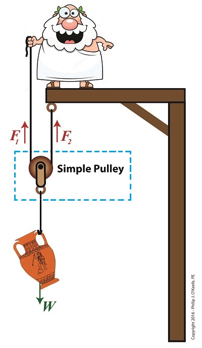
Using a free body diagram to understand simple pulleys ...

Solved a) draw the free body diagram for pulley a. b) draw ...
0 Response to "36 pulley free body diagram"
Post a Comment