36 intermatic t103 wiring diagram
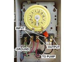
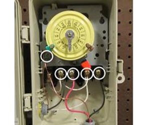
Connect the green ground wire to the green screw labeled GR. A: If your timer is 120V, or the T101 model, it will have 3 brass screws (terminals) underneath the plastic insulator cover. Check out the diagram below, or see the wiring diagram which comes with a new timer, or is printed on the door of the timer box. intermatic timer t104 wiring diagram - Collection T104m Timer Wiring Diagram White Neutral Wire How To Intermatic T104 And T103 T101 Timers. File Type: JPG. Source: sidonline.info. Collection of intermatic timer t104 wiring diagram. Click on the image to enlarge, and then save it to your computer by right clicking on the image.
w b and gr. hove the same wires - Intermatic Hardware & Accessories question. ... The wiring diagram for that timer is misleading. The 120 volt clock timer ...

Intermatic t103 wiring diagram
Symposia. ITMAT symposia enlist outstanding speakers from the US and abroad to address topics of direct relevance to translational science. Read more Intermatic T103 Wiring Diagram – wiring diagram is a simplified conventional pictorial representation of an electrical circuit. It shows the components of the circuit as simplified shapes, and the faculty and signal friends between the devices. A wiring diagram usually gives counsel practically the relative outlook and concurrence of devices ... Enclosures. Protect timer controls and receptacles from the elements with code-compliant outdoor enclosures. Our lineup of die-cast, low-profile and plastic weatherproof covers offers rugged protection in all types of applications, including industrial, commercial and residential. Learn More.
Intermatic t103 wiring diagram. Intermatic T103 Wiring Diagram T103 Timer Wiring Diagram New Intermatic T101 Timer Wiring Diagram is one of the pictures that are related to the picture before in the collection gallery, uploaded by autocardesign.org.You can also look for some pictures that related to Wiring Diagram by scroll down to collection on below this picture. If you want to find the other picture or article about ... Through the thousands of images on the web regarding intermatic timer wiring diagram, choices the top series along with best image resolution just for you, and this pictures is actually considered one of pictures choices in your very best graphics gallery concerning Intermatic Timer Wiring Diagram.Lets hope you may enjoy it. This kind of photograph (How To Wire T103 Timer pertaining to ... Assortment of intermatic r8806p101c wiring diagram. A wiring diagram is a simplified traditional photographic depiction of an electric circuit. It reveals the components of the circuit as simplified shapes, as well as the power and signal links between the tools. A wiring diagram normally provides details concerning the family member setting ... on Intermatic T103 Timer Wiring Diagram. Purchased a new T Outdoor Timer. On the inside, there are 5 screws, labeled A, 1, 2, 3, and 4. Additionally, 1 & 3 are labeled 'Line', and 2. The wiring is incorrect. The wiring diagram for that timer is misleading. The volt clock timer motor is connected internally to the "A" (neutral).
Click Images to Large View Intermatic T103 Wiring Diagram Free Wiring Diagram. How To Wire Intermatic Sprinkler And Irrigation Timers And. Click Images to Large View How To Wire Intermatic Sprinkler And Irrigation Timers And. Intermatic Digital Pool Timer W Freeze Protect Pe153pf. Intermatic T103 Mechanical Time Switch, Gray. ... The wiring diagram is a little difficult to comprehend but once you understand what it's showing you, it's simple and straightforward to hook up. The weatherproof box means it can be mounted outside but my handy pool shed ensures both my pump and timer are dry, ... Dimension: 1500 x 1281. DOWNLOAD. Wiring Diagram Images Detail: Name: intermatic t103 wiring diagram – Intermatic cell Wiring Diagram Best 06 Intermatic Et1125 Intermaticring Diagram Timer T101 T103. File Type: JPG. Source: irelandnews.co. Size: 677.49 KB. Dimension: 1280 x 1641. DOWNLOAD. This area is a growing library of the schematics, wiring diagrams and technical photos. Menu. Search for: Posted in Wiring. Intermatic Mechanical Time Switch T103 Wiring Diagram Posted by Margaret Byrd Posted on June 18, 2018. Intermatic timer t103 indoor 24 hour pool wiring diagram print www com media t104r won t turn pump on supplies depot t7401br t7401bc t7805b t104 series 40 amp 208 277 ...
Intermatic T104 Series 40 Amp 208 277 Volt Dpst 24 Hour Mechanical Time Switch Mechanism T104md89 The. Intermatic Pool Timer Wiring Diagram Site Resource. Wiring A T 105 104 120 240 Volt Timer Diy Ommp Pay It Forward Portland Patients Helping. Need Specific Instructions For Wiring An Intermatic T103 Double Pole Single Throw Timer To Water ... HistoryNet is the world’s largest publisher of best-selling history magazines. Our popular titles feature in-depth storytelling and iconic imagery to engage and inform on the the people, the wars and the events that shaped America and the world. 16.08.2018. 6 Comments. on Intermatic 240v Timer Wiring Diagram. Time Switches and Controls · Sensors · HVACR Solutions · Power Protection Duo · Timers · Hour Meters · Surge Protective Devices · Weatherproof Receptacle. The switch is wired to the timer. I switched out the T with the same and I think I messed up the wiring. Strip 1/2 inch of the covering from each insulated wire entering the Intermatic timer, with wire strippers. Two wire sets enter the timer. Each wire set contains two insulated and one bare wire. Step 5 Identify each wire terminal using the numbered labels, 1 through 4, for "Line" and "Load" terminal identification. Intermatic prints the labels ...
Model T103 DPST. Typical Wiring Diagram. - Jumper. Model T101 SPST. Equipment. Ground. Clock. Motor. Equipment. Ground. Clock. Motor. Equipment.3 pages
Intermatic T103 Wiring Diagram . October 27, 2019 0 Margaret Byrd . 0 . I bought an intermatic t103 and wire it time clock wiring diagram landscape light timer two hot wires for t104 t101 switch pool double pole doentation switches. I Bought An Intermatic T103 And Wire It As Follows Power To 1 3 Poles Lights 2 4 A Jumper From ...
Intermatic t101 timer wiring diagram t103 jpg trouble free pool landscape light two hot wires t104 off state full hooking up pump to relay switch parts dial mechanism for doentation time switches i bought an and wire it model t101m mechanical t7801b manualzz t106r 24 hour dt101 manual pdf supplementary pentair microbright lights Related . Reviews & Ideas. Related Posts. Free Vehicle Wiring ...
DOWNLOAD. Wiring Diagram Images Detail: Name: intermatic timer t104 wiring diagram - Collection T104m Timer Wiring Diagram White Neutral Wire How To Intermatic T104 And T103 T101. File Type: JPG. Source: sidonline.info. Size: 591.61 KB. Dimension: 1846 x 970. Variety of intermatic timer t104 wiring diagram.
Under a minute vid showing how to wire these timers (110/120V model)
Intermatic T103 Wiring Diagram Download. intermatic t103 wiring diagram - Building electrical wiring representations reveal the approximate areas as well as affiliations of receptacles, lights, as well as permanent electrical solutions in a building. Interconnecting wire paths may be revealed about, where specific receptacles or components should be on a common circuit.
2 HP, 24 FLA @ 120 VAC, 60 Hz, 5 HP, 28 FLA @ 240 VAC, 60 Hz. Number of Trippers Included. 1 ON/1 OFF. Pilot Duty (NO) 1000 VA, 120-240 VAC, 60 Hz. Pilot Duty Load Ratings Ranges. 1000 VA, 120-240 VAC, 60 Hz. Resistive Load Ratings Ranges. 40 A, 120-240 VAC, 60 Hz.
Intermatic Timer T104 Wiring Diagram - wiring diagram is a simplified tolerable pictorial representation of an electrical circuit. It shows the components of the circuit as simplified shapes, and the aptitude and signal links amongst the devices. A wiring diagram usually gives recommendation practically the relative face and deal of devices ...
For Use With Grainger Items 2E022, 4E024; Intermatic T103, T103P Timers; View All. Technical Specs Feedback. Documentation Intermatic Mechanical Timing Controls Wiring Diagram; Intermatic T103M Instructions; Alternate Products View All. Navigate previous. Navigate next. Web Price ...
Intermatic T103 Timer Wiring. I had bought a timer on Ebay and had a handyman install it on my outdoor sign at my office. The sign turns on and off manually but the timer does not run. I removed the breaker panel and ther are 3 wires going to the timer. One is the ground and the 2nd is from the breaker to the #1 Line post in the timer and the ...
Intermatic T103 Wiring Diagram. Assortment of intermatic t103 wiring diagram. A wiring diagram is a streamlined traditional pictorial representation of an electric circuit. It shows the elements of the circuit as streamlined shapes, as well as the power as well as signal links between the devices. A wiring diagram generally gives information about the…
Intermatic 240v Timer Wiring Diagram Download. intermatic 240v timer wiring diagram - Building circuitry representations show the approximate locations and affiliations of receptacles, lights, and also irreversible electrical solutions in a building. Adjoining wire paths might be shown approximately, where certain receptacles or components have to be on an usual circuit.
Wiring for model T103 intermatic timer
T103 timer requires neutral wire. T-103 has WG1570 120V clock motor Buy: WG1570 Intermatic T103 timer can be wired to control 120 Volt circuit -or- 240 Volt ...
WIRING INSTRUCTIONS:To wire switch follow diagram above. Use solid or stranded COPPER only wire with insulation to suit installation. See gauge selection table for normal service applica-tions. To make power connections remove 1/2 inch of insulation from wire ends. Insert bare ends of wire under the pressure plate of terminals.
You would wire a T103 for a 220V load as shown in the below pic. Not clearly shown on the pic but the 120V clock motor must be connected between terminal A and terminal 1. Hope this helps. added: btw, I took a look at your pic! Your existing T103 timer is wired correctly and in the same way as shown in the above wiring diagram.
From the thousands of images on the net about pool pump timer wiring diagram, we all selects the very best choices together with ideal image resolution just for you, and this images is one of graphics selections in your greatest images gallery regarding Pool Pump Timer Wiring Diagram.I really hope you can think it's great. This kind of photograph (How To Wire Intermatic T104 And T103 And ...
T103 Timer Wiring Diagram. WIRING INSTRUCTIONS: To wire switch follow diagram above. Use solid or stranded COPPER only wire with insulation to suit installation. See gauge selection. I purchased an Intermatic T timer switch and am unable to get the clock running. This is a wiring diagram for the T is this how you have it wired?.
Intermatic T103 Wiring Diagram. Currently, there are two white wires from A & 1 leading to the timer itself. My question is, in which locations (1 thru 4) do I wire the black and. I purchased an Intermatic T timer switch and am unable to get the clock running. This is a wiring diagram for the T is this how you have it wired?. Electrical - AC ...
WIRING INSTRUCTIONS: To wire switch follow diagram above. Use solid or stranded COPPER only wire with insulation to suit installation.1 page
Enclosures. Protect timer controls and receptacles from the elements with code-compliant outdoor enclosures. Our lineup of die-cast, low-profile and plastic weatherproof covers offers rugged protection in all types of applications, including industrial, commercial and residential. Learn More.
Intermatic T103 Wiring Diagram – wiring diagram is a simplified conventional pictorial representation of an electrical circuit. It shows the components of the circuit as simplified shapes, and the faculty and signal friends between the devices. A wiring diagram usually gives counsel practically the relative outlook and concurrence of devices ...
Symposia. ITMAT symposia enlist outstanding speakers from the US and abroad to address topics of direct relevance to translational science. Read more


0 Response to "36 intermatic t103 wiring diagram"
Post a Comment