36 gmrc 01 wiring diagram
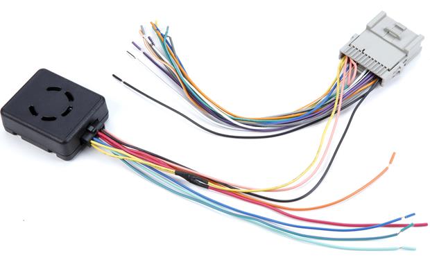
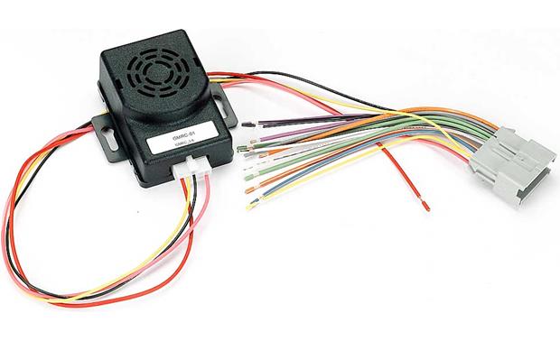
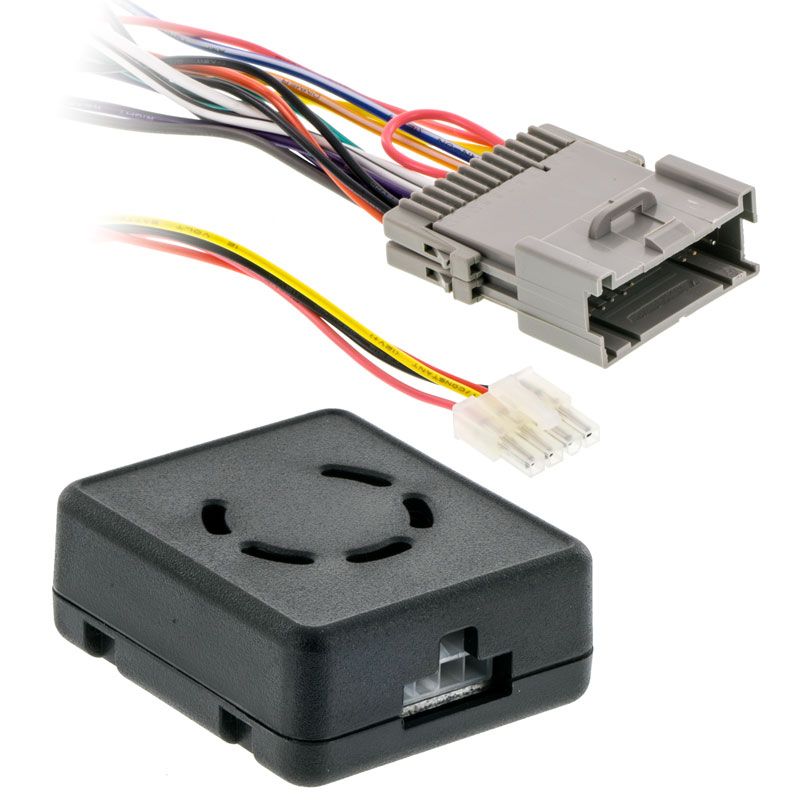
The Metra LC-GMRC-01 is designed to be used in a non-amplified GM vehicle or in vehicles where the OEM Amplifier has been bypassed (OnStar will not be retained). This harness retains all the factory warning chimes that would be lost when the OEM radio is removed. It also provides a 3 Amp 12 volt switched accessory for proper radio operation and ...
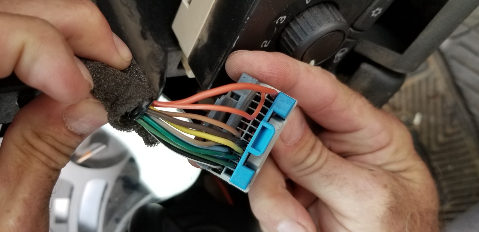
Metra LC-GMRC-01 GM Class... has been added to your Cart . Add a gift receipt for easy returns. Save with Used - Like New . $34.61 $34.61. FREE delivery: Saturday, Dec 11 Ships from: Amazon . ... 5.0 out of 5 stars Be patient and read your wire diagrams By nick on May 7, 2018 As with most stereo adapter harnesses, the wires are color matched to ...
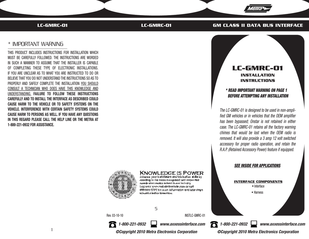
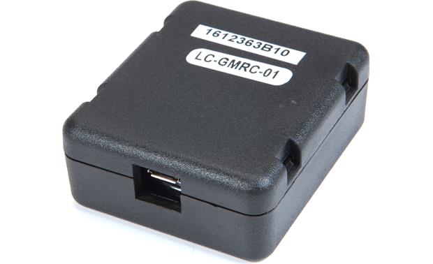
LC-GMRC-01 INSTALLING THE LC-GMRC-01 1. With all connections completed reconnect the negative battery terminal. 2. Plug the LC-GMRC-01 into the vehicle and into the radio. 3. Cycle the key by turning the ignition on then back off, then on again. TESTING THE LC-GMRC-01 1. Turn the radio on and test for proper balance and fader operation. 2.

Gmrc 01 wiring diagram
2 Posts. #15 · May 1, 2005. I just had the unit installed today. I've had two minor issues: First, the radio stays on even after I remove the key and exit the vehicle. I think the way it's supposed to work is that the radio stays on until the drivers door is open, then shuts off.
READ Gmrc-01 Wiring Diagram For Your Needs. Noco Battery Isolator Wiring Diagram Source: www.desktodirtbag.com Noco Battery Isolator Wiring Diagram Source: www.desktodirtbag.com. READ 1988 Ford F150 Wiring Diagram For Your Needs. Read electrical wiring diagrams from bad to positive in addition to redraw the signal being a straight range. All ...
Wiring Diagrams. Please choose a year from the menu at left to start your search. Skip to content. Wiring Diagrams. 91 yamaha 49cc riva scooter wiring diagram. ... Gmrc-01 wiring diagram. Wiring diagram for reversing a 120v motor with dpdt toggle youtube. Hes 9400 wiring diagram.
Gmrc 01 wiring diagram.
Gmrc 01 Wiring Diagram. Wiring Diagram 166 views. Search for: Recent Posts. 1 Ford F150 Wiring Harness Diagram. 2 Franklin Control Box Wiring Diagram. 3 91 Dodge Dakota Wiring Diagram. 4 1997 ford F150 Fuel Pump Wiring Diagram. 5 Bazooka Tube Wiring Diagram. Most Viewed Posts. 1 1976 Chevy Truck Wiring Diagram.
The LC-GMRC-LAN-01 is designed to provide a 12V/3A switched accessory output (red wire). Retained Accessory Power (R.A.P.): The ignition power source of most GM vehicles keeps the radio on until one of the doors is opened. This feature is called the R.A.P. (retained accessory power). The LC-GMRC-LAN-01 is designed to retain this feature.
Metra Lc Gmrc Lan 01 Wiring Interface Connect A New Car Stereo And. Metra Lc Gmrc 01 Gm Cl 2 Bus Interface Plete Overview For. Wire connections to be made LC-GMRC-LAN 12v Accessory from LC-GMRC-LAN To Radio SPDT Relay +12v Battery Fused 87 85 86 30 Red 87a Note: If the radio you See diagram. 4 LC-GMRC-LAN Installing the LC-GMRC-LAN 1.
GM 0S-01 Wiring Harness Radio Installation
x 17 color wiring diagrams · dashmat velourmat dashboard cover honda civic plush velour .. metra 70 radio wiring harness for toyota 87 up power 4 speaker pioneer deh xhd in dash cd mp3 receiver with hd radio mixtrax and .. gmrc 01 axxess non amplified non on interface harness for select pioneer deh p wiring harness moreover pioneer stereo deh mp wiring deh xui wiring harness diagram diagrams ...
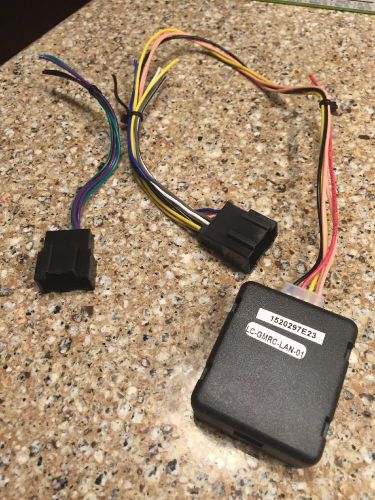
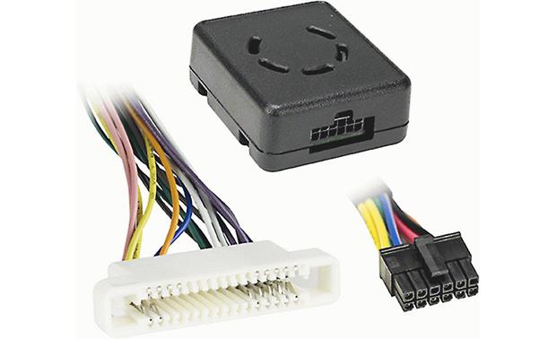
The LC-GMRC-01 is designed to retain this feature. 10-Pin to 24-Pin Harness: The wiring harness has a white 10-pin female connector (4 pins present) on one end and a gray 24-pin male connector (14 pins present) on the other end. The 10-pin connector plugs into the LC-GMRC-01 and the 24-pin connector interfaces with the existing factory plug.
Gmrc 01 Wiring Diagram. May 21, 2019. Amazon.com: Metra LC. www.amazon.com. Metra Online. As the Installerâ s Choice for dealer parts and car audio equipment, our team at Metra knows it is important to listen to our customers so that they keep listening with us. www.metraonline.com.
Metra LC-GMRC-LAN Wiring Interface Should come with basic wiring diagram for truly clueless people The LC-GMRC-LAN is designed to provide a 12V/3A switched accessory output (red wire). Warning Chimes: The LC-GMRC-LAN retains factory warning chimes through the use of an on-board speaker/5(78).
4 LC-GMRC-CL29 Wire connections to be made LD-LCGMRCLAN-01 harness (30-pin): • Connect the Yellow wire to the radios constant/memory wire. • Connect the red wire to the radios accessory wire. • Connect the Black wire to the radios ground wire. If the vehicle is non-amplified cut the RCA ends off and follow the
LC-GMRC-LAN-01 harness: • Connect the Yellow wire to the radios constant/memory wire. • Connect the red wire to the radios accessory wire. • Connect the Black wire to the radios ground wire. • Connect the Blue wire to the radios antenna turn on. • Connect the White wire to the radios left front (+) speaker wire. • Connect the White/Black wire to the radios left front (-) speaker wire.
Gmrc 01 Wiring Diagram . October 31, 2021 ... Metra Lc Gmrc 01 Wiring Interface Connect A New Car Stereo And Retain Factory Door Chimes Audible Safety Warnings In Select Gm Vehicles Without Amp Does Not Onstar At Crutchfield Axs Lc Gmrc 01 Lcgmrc01 Radio Replacement Interface For 2000
Gmrc-01 Wiring Diagram from metra-images.s3.amazonaws.com To properly read a electrical wiring diagram, one has to learn how the particular components in the program operate. For instance , in case a module is usually powered up also it sends out a new signal of fifty percent the voltage plus the technician does not know this, he'd think he ...
Lc-gmrc-01 | axxess integrate
Gmrc-01 Wiring Diagram. Installation instructions for part LC-GMRC Axxess Integrate. CAUTION! All accessories, switches, climate controls panels, and especially air bag indicator. Installation instructions for part LC-GMRC REV. 8/16/ From the LC- GMRC harness to the aftermarket radio: • Connect the Black wire to the ground.
Metra lc-gmrc-01 wiring interface connect a new car stereo ...
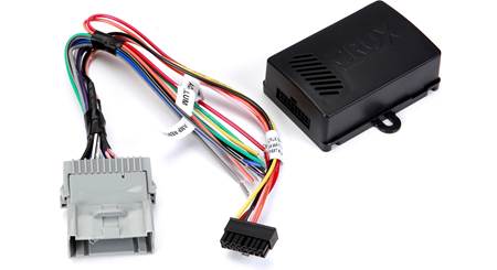
Provides accessory power (12-volt 10-amp) Retains R.A.P. if equipped. Used in non amplified systems or when removing amplified systems. Retains warning chimes. Small in size. USB updatable. Uses Micro B USB. Instruction Manual. Refer to the instruction manual and vehicle application guide for specific vehicle applications.

Installing the lc-gmrc-01 testing the lc-gmrc-01 installing ...
LC-GMRC-LAN-01 LC-GMRC-LAN-01 5 The LC-GMRC-LAN-01 is designed to be used in non-amplified GM vehicles or in vehicles that the OEM amplifier has been bypassed; Onstar is not retained in either case.The LC-GMRC-LAN-01 retains all the facto-ry warning chimes that would be lost when the OEM radio is removed. It will also provide a 3 amp 12 volt

Metra gmrc-01 car kit specification | manualzz
LC-GMRC-LAN-01 2 From the LC-GMRC-LAN-01 harness to the aftermarket radio: • Connect the Black wire to the ground wire. • Connect the Yellow wire to the battery wire. • Connect the Red wire to the accessory wire. • Connect the Blue wire to the power antenna wire. • If the aftermarket radio has an illumination wire, connect the Orange wire to it. ...
Gmrc-01
LC-GMRC-01 3 Connections to be made Connections to be made From the LC-GMRC-01 harness to the aftermarket radio: •• Connect the Black wire to the ground wire. • Connect the Yellow wire to the battery wire. • Connect the Red wire to the accessory wire. • Connect the Blue/White wire to the power antenna wire. • If the aftermarket radio has an illumination wire, connect the Orange
Metra lc-gmrc-01 radio wiring harness user manual | manualzz
LC-GMRC-01 INSTALLING THE LC-GMRC-01 1. With all connections completed reconnect the negative battery terminal. 2. Plug the LC-GMRC-01 into the vehicle and into the radio. 3. Cycle the key by turning the ignition on then back off, then on again. TESTING THE LC-GMRC-01 1. Turn the radio on and test for proper balance and fader operation. 2.
Metra lc-gmrc-01 wiring interface connect a new car stereo ...
Gmrc 01 Wiring Diagram. Metra electronics lc gmrc lan 01 users manual radio wiring harness user manualzz interface connect a new car stereo and retain factory door chimes audible safety warnings in select gm vehicles without amp does not onstar at crutchfield vt install 09 installation instructions for my 2011 chevrolet impala aftermarket ...

Lc-gmrc-lan-01 | axxess integrate
Metra Gmrc 01 Wiring Diagram. By Admin | November 21, 2017. 0 Comment. ... Customer Reviews Metra Lc Gmrc 01 Wiring Interface Connect A New Car Stereo And Retain Factory Door Chimes Audible Safety Warnings In Select Gm Vehicles Without Amp Does Not Onstar At.

Axxess lc-gmrc-01
Gmrc 01 Wiring Diagram- wiring diagram is a simplified adequate pictorial representation of an electrical circuit.It shows the components of the circuit as simplified shapes, and the aptitude and signal links amongst the devices. A wiring diagram usually gives opinion about the relative slope and deal of devices and terminals upon the devices, to help in building or servicing the device.
Metra vt-gmrc-01 wiring interface install a new car stereo ...
6. Connect the remaining wires between the GMRC-01 and the aftermarket radio using the Final Wiring Connections instructions described on page 2. STRIP SPLICE SOLDER TAPE RADIO DIAGRAM 1 GMRC-01 GM 24 PIN YELLOW BLACK RED *NOTE: If the volume of the GMRC-01 is too loud you will need to remove the cover and cut the solder connection where the
Metra lc-gmrc-01 economy radio replacement data bus interface with chime retention speaker
6. Connect the remaining wires between the GMRC-01 and the aftermarket radio using the Final Wiring Connections instructions described on page 2. STRIP SPLICE SOLDER TAPE R A D I O DIAGRAM 1 GMRC-01 GM 24 PIN YELLOW BLACK RED *NOTE: If the volume of the GMRC-01 is too loud you will need to remove the cover and cut the solder connection where the
New stereo, no power | gmtnation

Lc-gmrc-lan-09 installation instructions for lc-gmrc-lan-09 ...

Axxess gmrc-01 class ii gm chime retention interface for sale ...
Metra lc-gmrc-01 wiring interface connect a new car stereo ...

Metra lc-gmrc-01 gm class 2 data bus ... - amazon.com

Axxess lc-gmrc-lan-01

My 2011 chevrolet impala aftermarket stereo radio ...
Customer reviews: metra lc-gmrc-01 wiring interface connect a ...

Buy metra 70-7552 radio wiring harness for nissan 2007-up ...

1. http://www.autotoys.com/pics/instlc-gmrc-lan-01_web.pdf ...
H4o - hummer 4x4 off road
Find metra lc-gmrc-lan-01 gm lan data bus interface with ...
Kenwood dpx500bt owners - page 2 - chevy hhr network

Metra lc-gmrc-lan-09 axxess gmrc-lan interface gm 14-up

Amazon.com: metra lc-gmrc-01 gm class 2 data bus interface ...

Axxess lc-gmrc-01

Axxess lc-gmrc-01
Axxess lc-gmrc-04 wiring interface

Chevrolet silverado-interface de radio axxess pt1 - youtube

Lc-gmrc-cl29 gm class-2/lan-29 data bus interface | manualzz

Metra lc-gmrc-01 gm class 2 data bus interface car ...

Metra lc-gmrc-01 wiring interface connect a new car stereo ...
New stereo, no power | gmtnation

Axxess gmrc-01 class ii gm chime retention interface for sale ...
0 Response to "36 gmrc 01 wiring diagram"
Post a Comment