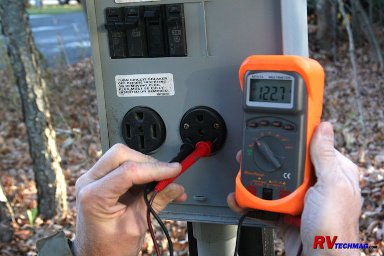
35 rv transfer switch wiring diagram
Size: 301.61 KB. Dimension: 1020 x 833. DOWNLOAD. Wiring Diagram Pictures Detail: Name: rv transfer switch wiring diagram - Generac 200 Amp Transfer Switch Wiring Diagram Best s Rv Transfer Switch Wiring Diagram Wiring solutions. File Type: JPG. Source: sushiofnaples.net. Size: 97.79 KB. Dimension: 764 x 407. Every symbol that is presented on the diagram reveals specific circuit element. The most common components are capacitor, resistorbattery. There are also other components like floor, switch, engine, and inductor. Everything rides on circuit that's being constructed. According to earlier, the lines at a 50 Amp Rv Wiring Diagram signifies wires.
Rv Automatic Transfer Switch Wiring Diagram- wiring diagram is a simplified up to standard pictorial representation of an electrical circuit.It shows the components of the circuit as simplified shapes, and the capability and signal connections amid the devices.

Rv transfer switch wiring diagram
Rv Transfer Switch Wiring Diagram - rv transfer switch wiring diagram, Every electrical arrangement is made up of various diverse components. Each component should be placed and connected with different parts in specific manner. If not, the arrangement won't function as it ought to be. The 3-way changeover switch shown in the below diagram is a manual changeover switch of a specific company, model number is written on the diagram. You can use any changeover switch and wire it up on the same lines. Here is a schematic diagram in PDF and this is a wiring diagram in PDF. Charging the Batteries from AC Shore Line or AC Generator ... Home > Converter/Charger & Automatic Transfer Switch Support > Automatic Transfer Switches > Transfer Switch: Wiring Diagrams (50 amp) Transfer Switch: Wiring Diagrams (50 amp) Eva Mitic. Jun 23, 2021. 3737 Inside Lid Image . Wiring Diagram Products covered in this article: GP-TS-30 ...
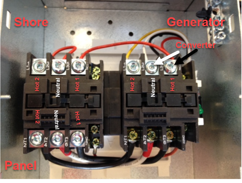
Rv transfer switch wiring diagram. Rv automatic transfer switch wiring diagram 30 amp rv wiring diagram wiring diagram rv automatic transfer switch wiring diagram wiring diagram is a simplified up to standard pictorial representation of an electrical circuit. 30 amp transfer switch wiring. Output to panel. Do not use the double pole 30 amp breaker with 2 hot wires to install. If you need to see how the transfer switch is tied in, look at the diagram above under the transfer switch section. Since most RVs come with a converter built in, the below picture shows where in the system it lives. Some converters are wired into the AC breaker box, however, most are just plugged into a plug that is built into the back of RV ... An automatic transfer switch is basically a three way switch that switches between two inputs and connects them to a single common output. A transfer switch is located prior to the breaker panel. It intercepts the shore power cord feed to the breaker panel. The output of the transfer switch goes to the breaker panel's inputs. That switch was made by Progressive Dynamics and worked very well so I ordered the Progressive Dynamics PD52 automatic transfer switch for the 2014 SRX. The SRX has 50 amp service and the PD52 is designed for 50 amp RV systems. I ran 10 gauge wire for my generator from the kingpin area of the SRX to the power center in the kitchen area.
Onan 5500 Rv Generator Wiring Diagram. Installation manual onan generator fuel pump voltage source irv2 forums need a wiring diagram for gen set the start stop controll panel it is 4 0 bfa 1r 16004c serial number 5500 to know wire id of wires remote on 5 bga red blue seems be outputs 028 00022 yakima un modifying related 4000 emerald bge rv ... Generator Groundig Transfer Switch Electrical Connection Switches. Blue Sea 6007 Switch Wiring Diagram Add A Battery Kit Best Of Boat Wiring Boat Boat Projects. Pin On Marine Shore Rv Power Solutions. 50 Amp Plug Wiring Diagram That Makes Rv Electric Wiring Easy Home Electrical Wiring Electrical Projects Electricity. RV Electrical Diagram (Wiring Schematic) Understanding you campers electrical wiring can be very confusing. Use the RV electrical diagram we made below to get an understanding of what powers what and to learn how an RV electrical system works. Before installing a RV transfer switch you will want to make sure that all power sources to the RV are disconnected, including generators, shore lines and batteries. Remove the 4×4 boxes and disconnect any wires that are connected to the older style units. The automatic RV transfer switch has decals where everything gets hooked up.
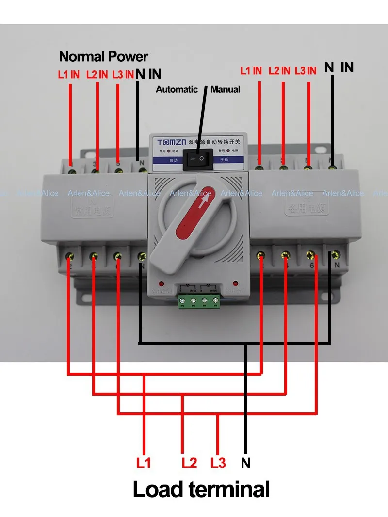
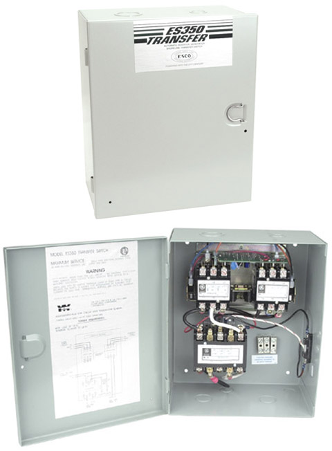
A recreational vehicle, or rv, will typically have two methods of introducing 120 volt electricity; You Need To Know Can You Hook A 30 Amp Rv To 50 Amp Power Mortons On The Move from mortonsonthemove.com A transfer switch is a device which automatically switches between the power supplies to ensure both are. A 6 pole/double throw, 600 volt, 32 amp, rotary switch for switching between two power sources, and an off position to boot! This is very similiar to switches installed in marine applications for this very purpose, but absent in rv applications. Although marine manual transfer switches are very expensive, they typically only have 2 poles. 120V, 30A, 60 Hz. Proprietary electrical interlock. Time delay at power up. Transfers to generator power automatically when energized after 30 second delay. When both shore power and generator power are available, generator dominates after a 30 second delay. Once the generator is shut down, shore power activates after a 3-4 second delay. Step 2. Consult the manufacturer's wiring diagram, which is usually fixed to the inside of the transfer box case, for installation details specific to your unit. The generator and the shore power cord are and the circuit breaker board inside the RV is connected to terminals "downstream" of the transfer switch.
~~~~~Does off-grid solar confuse you? Check out my DIY friendly website for solar system blueprints, recommended components and much more...

rv automatic transfer switch wiring diagram - You'll need a comprehensive, skilled, and easy to understand Wiring Diagram. With such an illustrative guide, you'll be capable of troubleshoot, stop, and complete your assignments without difficulty.
Rv Transfer Switch Wiring Diagram Source: i.pinimg.com. READ Garage Door Sensors Wiring Diagram For Your Needs. Read cabling diagrams from bad to positive plus redraw the circuit as a straight range. All circuits are the same - voltage, ground, single component, and changes. Rv Transfer Switch Wiring Diagram Source: www.dmbruss.com.
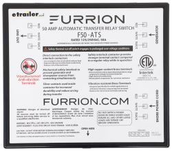
Hello, Do you have anything like a wiring diagram of how to install a Furrion Transfer Switch - 50 Amp Item # F50ATS? We have a Week End Warrior that you have to unplug the generator to plug in the shore power or vise versa.
Rv Automatic Transfer Switch Wiring Diagram from static-cdn.imageservice.cloud. To properly read a cabling diagram, one offers to find out how the particular components inside the system operate. For instance , in case a module is usually powered up and it also sends out the signal of fifty percent the voltage in addition to the technician does ...
ATS is an abbreviation for automatic transfer switch, and its job is to be a traffic cop between the pedestal shore power and your on-board generator power. They come in two sizes: 30-amp and 50-amp RV power. They can also include a built-in surge protector. Some also have EMS under/over voltage protection.
Automatic Transfer Switches. Power quality in RV parks is affected by electrical loads, weather conditions, faulty wiring, undersized, deteriorating, or miswired electrical connections. Due to the increased sophistication of new RVs, the additional monitoring and diagnostic features as well as the benefits of a Surge Guard* transfer switch are ...

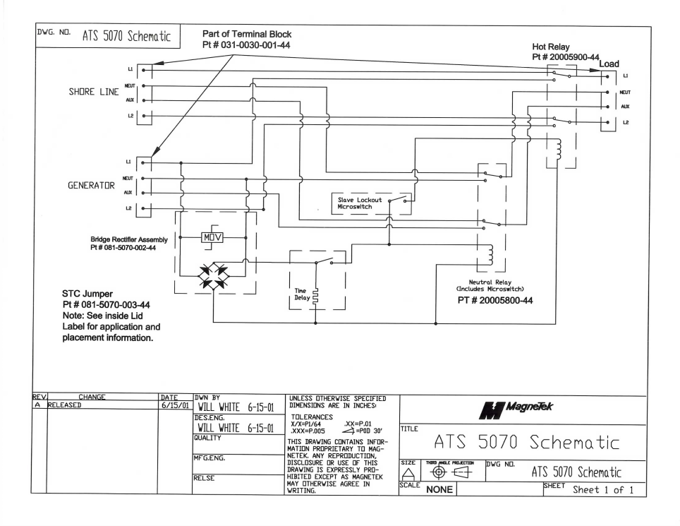
Generator automatic transfer switches ats5070 switch wiring diagram for installing furrion 50 ats go power three esco 240 vac pd52 winco asco 100 Rvelectricity Generator Automatic Transfer Switches 101 Rv Travel Ats5070 Generator Automatic Transfer Switch Wiring Diagram For Installing Furrion Transfer Switch 50 Amp Item F50ats Etrailer Com Furrion Automatic Transfer Switch 50 Amp… Read More »
Automatic Transfer Switch Circuit Diagram Genset Controller Within, size: 800 x 600 px, source: saleexpert.me. Here are some of the top drawings we get from numerous resources, we hope these pictures will be useful to you, and also hopefully very pertinent to exactly what you want concerning the Transfer Switch Wiring Diagram is.

I describe and replace a Parallax ATS 301 30amp RV transfer switch in a 2006 Holiday Rambler Arista. http://www.parallaxpower.com/ats301-transfer-switch-ats3...
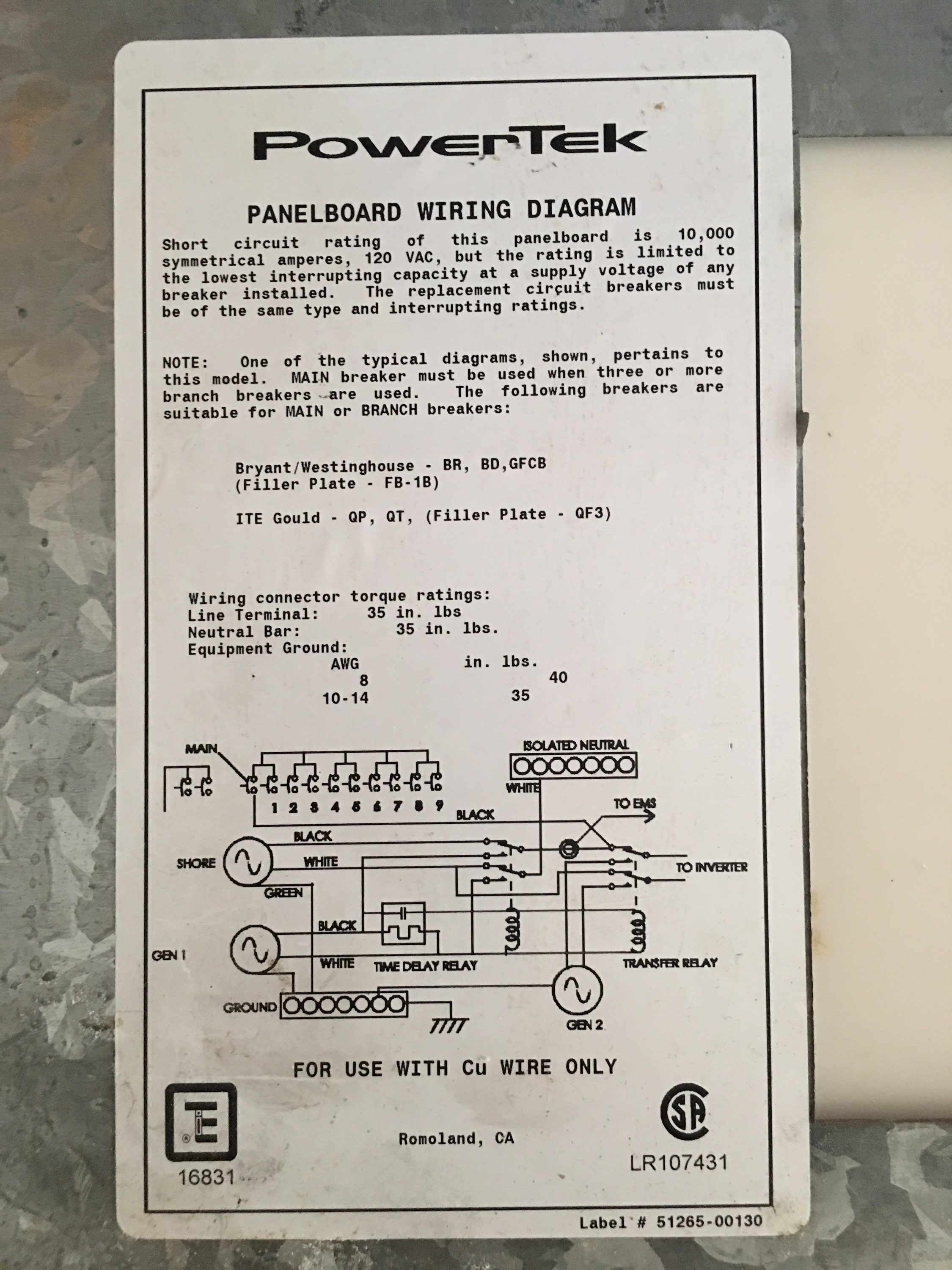
only qualified service personnel should install or troubleshoot this transfer switch! all applicable codes and standards must be met when installing this device. see wiring diagram inside of the cover and on the back of this page. improper handling or installation may cause serious injury or death.
Home > Converter/Charger & Automatic Transfer Switch Support > Automatic Transfer Switches > Transfer Switch: Wiring Diagrams (50 amp) Transfer Switch: Wiring Diagrams (50 amp) Eva Mitic. Jun 23, 2021. 3737 Inside Lid Image . Wiring Diagram Products covered in this article: GP-TS-30 ...

The 3-way changeover switch shown in the below diagram is a manual changeover switch of a specific company, model number is written on the diagram. You can use any changeover switch and wire it up on the same lines. Here is a schematic diagram in PDF and this is a wiring diagram in PDF. Charging the Batteries from AC Shore Line or AC Generator ...
Rv Transfer Switch Wiring Diagram - rv transfer switch wiring diagram, Every electrical arrangement is made up of various diverse components. Each component should be placed and connected with different parts in specific manner. If not, the arrangement won't function as it ought to be.


0 Response to "35 rv transfer switch wiring diagram"
Post a Comment