37 refrigeration cycle diagram pdf
Actual Vapor‐Compression Refrigeration Cycle Fig. 5-4: T-s diagram for actual vapor-compression cycle. Most of the differences between the ideal and the actual cycles are because of the irreversibilities in various components which are: 1-In practice, the refrigerant enters the compressor at state 1, slightly superheated vapor, instead of saturated vapor in the ideal cycle. 2- The suction ... PDF. Novel Refrigeration Cycle with Continuous Cooling Turbo Compressor and Condensing Ejector Using Water as Refrigerant, ... PDF. Noise And Cycle Performance Of A New Damping Valve For Compressor, Bo Huang and Hao Yuan. PDF. Experimental Study on P-V diagram and motion curve of suction and discharge valve in reciprocating compressor, Gang Huang, Xuebao Shen, and Zhiqi Yan. PDF…
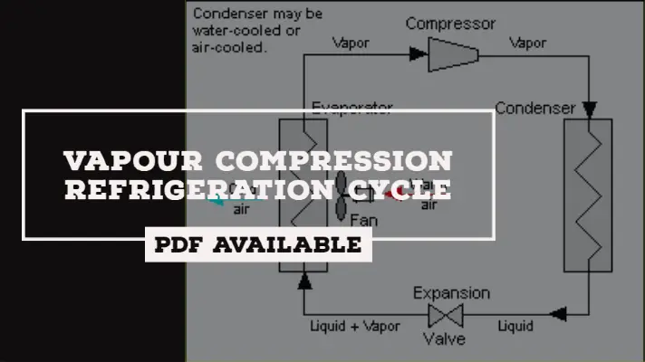
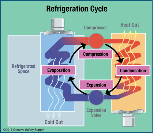
Refrigeration cycle is the basis of all refrigeration systems. So refrigeration cycle should be known to understand the refrigeration system. Some basic refrigeration cycles are discussed here through different diagrams. 2.2 VAPOUR COMPRESSION CYCLE Vapour compression cycle is an improved type of air refrigeration cycle in which a suitable ...
Refrigeration cycle diagram pdf
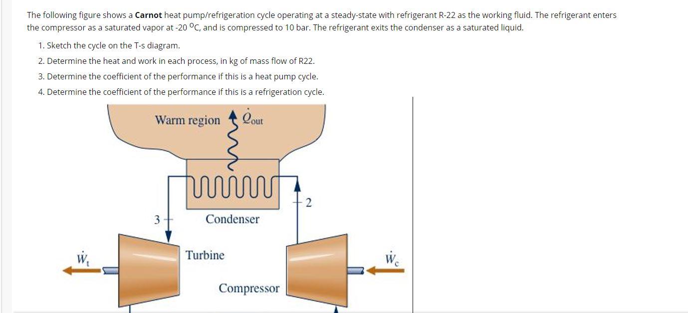
Pressure-enthalpy diagram for refrigerants ... Alternatives to vapor compression refrigeration system ... Compression Refrigeration Cycle. Component.50 pages Carnot cycle, here the enclosed area is a rectangle. This cycle is often used as a comparison cycle to describe the quality of the cyclic process. The direction of the cyclic process in theT-s diagram determines w hether this is a heat pump cycle (refrigeration cycle) or a work machine cycle (steam power cycle). Refrigeration cycles are anti- Figure 10: Carnot refrigeration cycle ; (a) schematic diagram and (b) T – S Diagram for Carnot Cycle 25 Figure 11: Refrigerant Safety Group Classifications 30 Figure 12: p-h diagram for vapor compression cycle (ideal) 34 Figure 13: p-h Diagram for vapor compression cycle (actual) 36 Figure 14: Subcooling liquid from condenser 38
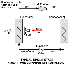
Refrigeration cycle diagram pdf. THE IDEAL VAPOR-COMPRESSION REFRIGERATION CYCLE The vapor-compression refrigeration cycle is the ideal model for refrigeration systems. Unlike the reversed Carnot cycle, the refrigerant is vaporized completely before it is compressed and the turbine is replaced with a throttling device. Schematic and T-s diagram for the ideal vapor-compression ... REFRIGERATION CYCLE The vapor-compression refrigeration cycle is the ideal model for refrigeration systems. Unlike the reversed Carnot cycle, the refrigerant is vaporized completely before it is compressed and the turbine is replaced with a throttling device. 5 Schematic and T-s diagram for the ideal vapor-compression refrigeration cycle. Download Full PDF Package. This paper. A short summary of this paper. 22 Full PDFs related to this paper. READ PAPER. Air-Conditioning and Refrigeration. Mechanical Engineering Handbook. Download. Air-Conditioning and Refrigeration. Mechanical Engineering Handbook. Pawan Gupta ... producing cycle, as those reviewed under . Chapter 17: Power, would produce a refrigeration effect if run backwards in the T-s diagram. Most of the time, heat pumps (used for heating) are considered under the refrigeration heading, since the ... Q >0 in the refrigeration case (heat inputs), and Q
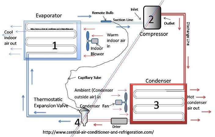
by LOHW LIONG · 2012 — Reversed Carnot Cycle. 8. 2.2. Ideal vapor compression refrigeration cycle (a) T-s diagram, (b) P-h diagram. 10. 2.3. Schematic diagram of the vapor ...24 pages This is how the refrigeration cycle diagram looks: Yeah, it seems complicated at first, but it will be easier to understand once I have explained the refrigeration cycle diagram section by section. It important to understand the basic refrigeration cycle, to comprehend what is going on within the air conditioner units, we cannot see it. The vapor compression refrigeration cycle is a common method for ... constant temperature reservoirs and the T-s diagram for the working fluid.15 pages refrigerators, and the cycles on which they operate ... Schmatic and T-s Diagram for Ideal Vapor- ... The Ideal Vapor-Compression Refrigeration Cycle.25 pages
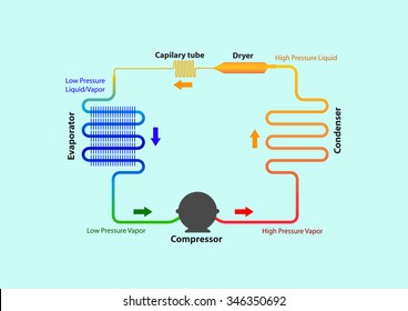
The log p-h diagram shows the thermodynamic state vari- ables in the respective phase. • pressure p. • specific enthalpy h. • temperature T. • specific volume v. Figure 4: Wet refrigeration Cycle - The expander has been substituted by a throttling valve. If an expander had been used the line from d to a would be a vertical line. This is also done for mechanical reasons. The refrigeration cycles can also be represented in a P-H diagram. Figure 5: P-H diagram representation of a dry refrigeration cycle The refrigeration cycles can also be represented in a P-H diagram. Figure 5: P-H diagram representation of a dry refrigeration cycle. 4 key components needed in a basic refrigera=on cycle: 1. Compressor. 2. Condenser. 3. Evaporator ... Compresses low pressure refrigerant vapor from the.16 pages
Vapour Compression Refrigeration Cycle Components Working Process Applications Pdf
Thermodynamic cycle 2 Power cycles Heat engine diagram. Thermodynamic power cycles are the basis for the operation of heat engines, which supply most of the world's electric power and run almost all motor vehicles. Power cycles can be divided according to the type of heat engine they seek to model. The most common cycles that model internal combustion engines are the Otto cycle, which models ...
2
Refrigeration Cycle Evaporator Condenser / Receiver Expansion Device. Vapor Compression Cycle. Th MOVEMENT Cooling by the removal of heat The MOVEMENT of HEAT from a place where it is notot a ted to a wanted to a place where it is unobjectionable. How Heat is Removed. What is heat? A form of energy What is cold?
Definition Of One Ton Of Refrigeration
Figure 10: Carnot refrigeration cycle ; (a) schematic diagram and (b) T – S Diagram for Carnot Cycle 25 Figure 11: Refrigerant Safety Group Classifications 30 Figure 12: p-h diagram for vapor compression cycle (ideal) 34 Figure 13: p-h Diagram for vapor compression cycle (actual) 36 Figure 14: Subcooling liquid from condenser 38
2
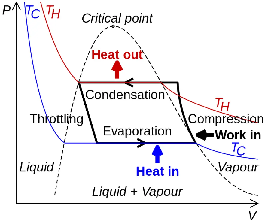
Carnot cycle, here the enclosed area is a rectangle. This cycle is often used as a comparison cycle to describe the quality of the cyclic process. The direction of the cyclic process in theT-s diagram determines w hether this is a heat pump cycle (refrigeration cycle) or a work machine cycle (steam power cycle). Refrigeration cycles are anti-
Energy And Exergy Analysis Of Refrigeration Systems Intechopen
Pressure-enthalpy diagram for refrigerants ... Alternatives to vapor compression refrigeration system ... Compression Refrigeration Cycle. Component.50 pages

Simple Refrigeration Cycle Hindi Urdu Youtube Refrigerator Refrigeration And Air Conditioning Electrical Circuit Diagram

Cascade Refrigeration Wikipedia

Refrigeration Cycles Mech Engineering Thermodynamics Ucl Wiki

Refrigeration Cycle Basics In An Hvac Refrigeration System With Expla Refrigeration And Air Conditioning Air Conditioning System Design Air Conditioning System
Vapour Compression Refrigeration Cycle Components Working Process Applications Pdf
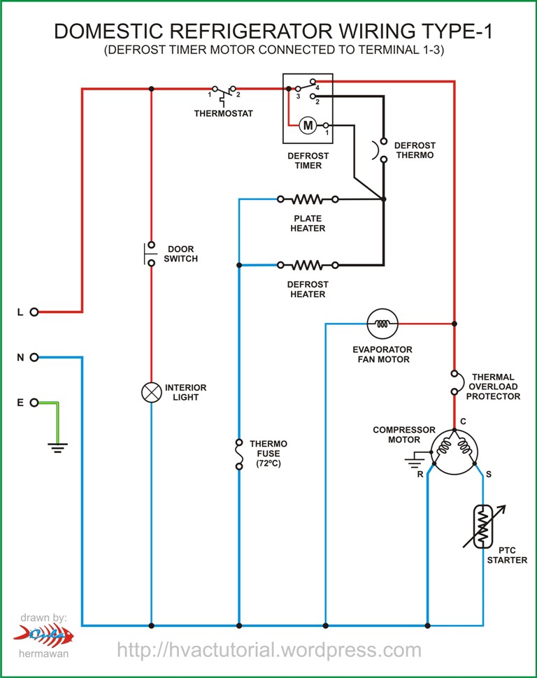
Domestic Refrigerator Wiring Hermawan S Blog Refrigeration And Air Conditioning Systems
What Is The H S Diagram For Vapour Compression Refrigeration Cycle Quora
Solved Http Homepages Wmich Edu Cho Me432 Appendix2 En Chegg Com
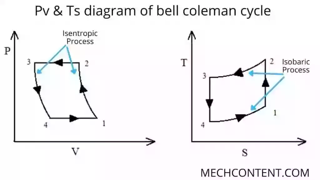
Bell Coleman Cycle With Pdf Bell Coleman Cycle Air Refrigeration Bell Coleman Refrigeration Cycle Mech Content

Air Conditioning Circuit And Cycle Diagram Pdf Air Conditioning Phases Of Matter
A Ton Of Refrigeration Effect Is Defined As The

Simple Refrigeration Cycle Hindi Urdu Youtube Refrigerator Refrigeration And Air Conditioning Electrical Circuit Diagram

Typical Refrigeration Cycle Diagram Royalty Free Cliparts Vectors And Stock Illustration Image 21930696
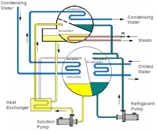
Absorption Chiller Pump

Refrigeration System An Overview Sciencedirect Topics
Module 2 Refrigeration Inside The Box Cibse Journal

Simple Refrigeration Cycle Hindi Urdu Youtube Refrigerator Refrigeration And Air Conditioning Electrical Circuit Diagram
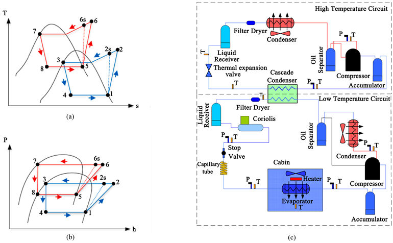
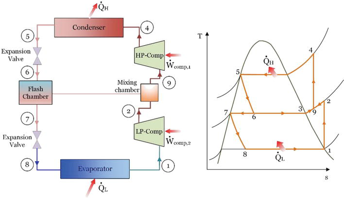
Novel Cascade Refrigeration Cycle For Cold Supply Chain Of Covid 19 Vaccines At Ultra Low Temperature 80 C Using Ethane R170 Based Hydrocarbon Pair
Basic Refrigeration Cycle

Auto Cascade Refrigeration System Hermawan S Blog Refrigeration And Air Conditioning Systems
Secondary Refrigerant Systems

Thermal Efficiency Of Refrigeration System

Performance Analysis And Development Of A Refrigeration Cycle Through Various Environmentally Friendly Refrigerants Springerlink
Refrigeration Cycle Diagram Vector Illustration Stock Vector Royalty Free 346350692
1
Ammonia Refrigeration Creative Safety Supply

Pdf Vapour Compression Cycle
Energy And Exergy Analysis Of Refrigeration Systems Intechopen

File Cascade Freezer Cycle German Pdf Wikimedia Commons

Types Of Refrigeration System Classification Of Refrigeration

Fire Fighting System For Building Air Conditioning Cycle Pdf

Refrigeration Cycles Mech Engineering Thermodynamics Ucl Wiki
0 Response to "37 refrigeration cycle diagram pdf"
Post a Comment