5 ph diagram for refrigeration cycle
Principles of Refrigeration MAE 554 Professor H. Ezzat Khalifa Syracuse University P-h Chart for R134a (SI Units) ... P-h Diagram for Real Vapor Compression Cycle ... P-h Diagram for 2-Stage VCC with Subcooler. 11 0.6 0.8 1.0 1.2 1.4 1.6 1.8 2.0 2.2 2.4-40 -30 -20 -10 0 10203040 50 Draw the cycle on a P-h diagram and determine: (a) B.P. of the compressor if Mech. efficiency is 75% (b) Bore and stroke of the cylinder if UD = 1.25 (c) Condenser water required for a temperature rise of 6°C. Solution: The various state points of the cycle shown in Fig. 36.26 may be obtained with the help of P-h chart as given below:
If you are interested in learning how a refrigeration system works, it is helpful to understand from the Ph (Pressure Enthalpy) chart perspective. It makes our life much easier. This is how the refrigeration cycle diagram looks: Yeah, it seems complicated at first, but it will be easier to understand once I have explained the refrigeration ...

Ph diagram for refrigeration cycle
(in theory) at a constant entropy. In an ideal cycle, the refriger-ant vapor would enter the compressor as a saturated vapor…no superheat. The Ideal Cycle If the operating temperatures and pressures are known, the refrigeration system can be plotted on the P-H diagram. Lets assume our system is operating at a -20ºF evaporator and 100ºF ... 2000 VM사이클 히트펌프 기초 설계프로그램 Basic Simulation for Vuilleumier Cycle Heat Pump 박병덕 Byung-Duck Park... of Mechanical Engineering * 주소: 경북 상주시 가장동 386 Sangju National Univ., Ph.D. from Kyushu Univ. Tel : +82-054-530-5335 386... 1 The schematic diagram of VHMP cycle 2. VMHP의 성능 시뮬레이션 VMHP는 열 구동형의 히트펌프로서 도시 2.1 VMHP의... Acids and bases are two important concepts in chemistry. To really understand the difference between acids and bases, it’s essential to understand what pH is. Learn more about pH levels and what they mean for you in your day-to-day life wit...
Ph diagram for refrigeration cycle. Ph diagram for refrigeration cycle Efficiency - Working with the Refrigerant Circuit To measure what is happening the first thing to do is to find the temperatures and pressures at key points in the circuit. Measurement points for Temperature T and Pressure P can be used to define the process. The Vapour Compression Cycle, Practical Circuit and ... Water is considered a neutral because its acid and base properties cancel each other out. However, drinking and natural water have a more diverse range. Michael Heim / EyeEm / Getty Images At 25 C, the pH of pure water is very close to 7. A... Learn how to draw a cycle for ideal conditions on a PH chart.Please provide feedback on this module by selecting "Like" or "Dislike". Your feedback and comme... The Carnot thermal COP of a HACD is derived in Herold et al (1996) by coupling a Carnot power production cycle to a Carnot heat pump cooling cycle. It is assumed that (1) the work produced by the power cycle equals the work consumed by the cooling cycle, and (2) the heat rejection temperature of the power cycle equals the heat rejection ...
The log p-h diagram shows the thermodynamic state vari- ables in the respective phase. • pressure p. • specific enthalpy h. • temperature T. • specific volume v. Refrigeration cycle is the basis of all refrigeration systems. So refrigeration cycle should be known to understand the refrigeration system. Some basic refrigeration cycles are discussed here through different diagrams. 2.2 VAPOUR COMPRESSION CYCLE Vapour compression cycle is an improved type of air refrigeration cycle in which a suitable ... The Best and Completed Full Edition of Diagram Database Website You Can Find in The Internet ... Honda Accord Dash Light Wiring Diagram Diagram For Lights Does This Look Right Second Horn Relay Diagram Alarm Wiring Diagrams Carbine Alarms Tm Diagram Kelistrikan Vario 125 Ford Windstar Vacuum Diagram Camaro Wire Diagram Diagram For Offices Ford Bronco Fuse Diagram Blower Motor Wiring Diagram Suzuki Gs750 Wiring Diagram Diagram De Geely Ck Wind Diagram Hyundai Accent Stereo Wiring Diagram Hvac Heat Pump Wiring Diagram Plug Wiring Diagram Australia 7 Pin Es Un Diagrama De Ganttprender Y Utiliz The P-h diagram is another convenient diagram often used to illustrate the refrigeration cycle. The ordinary household refrigerator is a good example of the application of this cycle. Results of First and Second Law Analysis for Steady-Flow Component Process First Law Result Compressor s = const. Wmhh () in =−21
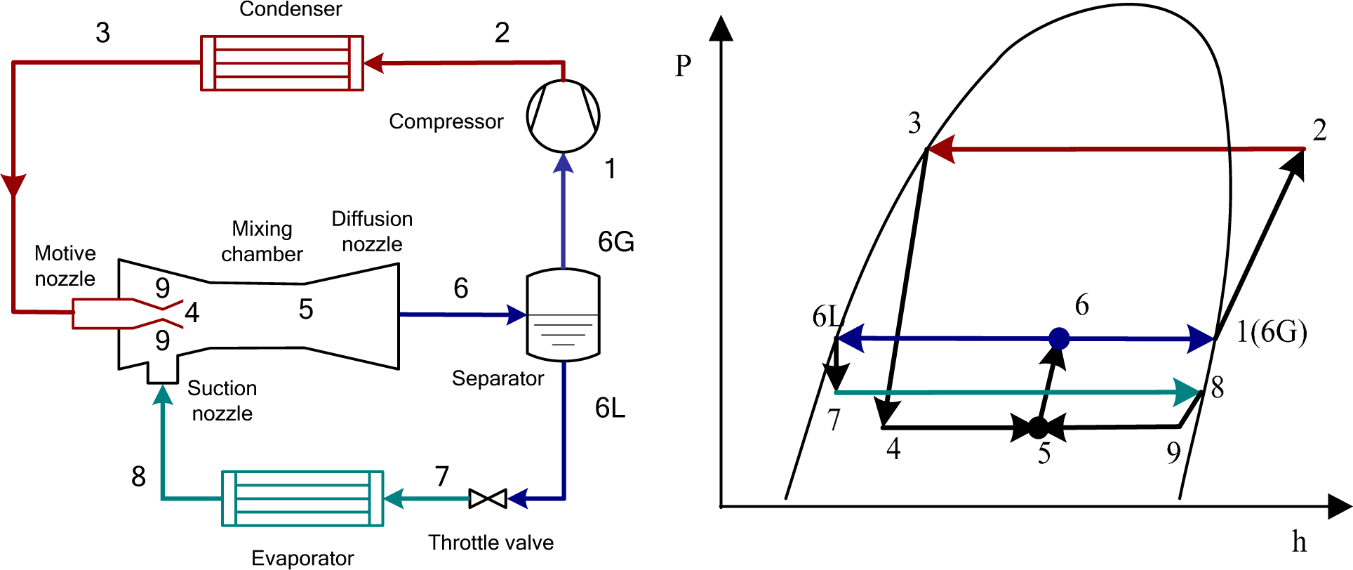
Download scientific diagram | p-h diagram of ejector-expansion refrigeration cycle from publication: Review on cycle modifications of transcritical CO2 refrigeration and heat pump systems ... The Basic Refrigeration Cycle Mechanical refrigeration is accomplished by continuously circulating, evaporating, and condensing a fixed supply of refrigerant in a closed system. Evaporation occurs at a low temperature and low pressure while condensation occurs at a high temperature and high pressure. The basic refrigeration cycle for beginners If we are interested in learning how a refrigeration system works, it is helpful to understand from the Ph (Pressure Enthalpy) chart perspective. It makes our life easier. This is how the refrigeration cycle diagram looks: Yeah, it seems complicated at first, but it will be easier to... is a collection of simulation models for refrigeration systems for cycle analysis, sizing of main components, energy analysis and optimization. It also contains a refrigerant property calculator and can draw, for example, log(p)-h diagrams. is a program for calculating, comparing and plotting thermophysical properties of...

Explain with schematic the working of a refrigeration ...
The usual range of pH values runs from 0 to 14, but is it possible to have a negative pH value? Find out what negative pH means. JazzIRT/Getty Images The usual range of pH values runs from 0 to 14. If you are given the molarity of hydrogen ...

Figure2.2: p-h diagram of simple refrigeration cycle ...
The refrigeration cycles can also be represented in a P-H diagram. Figure 5: P-H diagram representation of a dry refrigeration cycle Refrigerant fluid choice: We now turn our attention to the fluids. Usually, one tends to pick pL as low as possible, but not below atmospheric pressure. Thus, the refrigerant chosen needs to have a normal boiling point compatible with the lowest temperature of the cycle (usually 10oC

Ph Diagram For Refrigeration Cycle - General Wiring Diagram
J. Chen, H. Chang and S.-R. Chen, Simulation Study of a Hybrid Absorber– Heat Exchanger Using Hollow Fiber Membrane Module for the Ammonia-Water Absorption Cycle, Int. J. of Refrigeration, 29 1043-1052, 2006.

Refrigeration: Ph Diagram Refrigeration Cycle
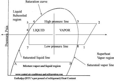
Figure 1-6 Refrigeration Cycle P-H Diagram Image Figure 1-7 Properties of Refrigerant at -20℉ Figure 1-8 Properties of the Refrigerant at 105℉ H 1is the saturated suction of the compressor at -20ºF. at no losses. H 2is the compressor discharge point at no losses. H 5is the saturated liquid at 105ºF condensing temperature.
Refrigeration: Ph Diagram Refrigeration Cycle
P-H Diagram for Ideal Conditions e . H 1 = h f based on temperature at 'd' (exit of condenser) H 2 = h g based on temperature at 'a' (exit of evaporator) Note 1: If there is super-heating in the evaporator, H 2 can not be obtained from P-H table Note 2: If there is sub-cooling in the condenser, H 1 can not be obtained from P-H table

Wiring Diagram: 29 Ph Diagram For Refrigeration Cycle
P-h diagram of vapor compression refrigeration cycle Generally, the vapor compression refrigeration system consists of a condenser, an expansion valve, an evaporator, and a compressor. The vapor ...

Natracare organic cotton curved panty liners
The Best and Completed Full Edition of Diagram Database Website You Can Find in The Internet ... Car Wiring Diagram For Lights Mount Transformer Wiring Diagram Ford F 150 302 Vacuum Lines Diagram And Stratton 17 5 Hp Engine Diagram Silverado Cluster Wiring Diagram Dodge Wiring Diagram Controller Wiring Diagram 7 Wire Dodge Journey Fuse Panel Diagram Combustion Engine Diagram Ford Edge Fuse Panel Diagram Ford Expedition Roof Wiring Diagram Super Beetle Wiring Diagram For Diagram De Taller Fiat 500 Chevy 350 Wiring Diagram Meter Wiring Diagram For Ford Sg Wiring Diagrams 2 Humbucker F450 Radi

34 Ph Diagram For Refrigeration Cycle - Wiring Diagram ...
Academia.edu is a platform for academics to share research papers.
Wiring Diagram: 29 Ph Diagram For Refrigeration Cycle
It is recommended that the engineer get a copy of the P-H diagram for R-134a and the other common refrigerants. These diagrams can be found in the ASHRAE Fundamentals book. A sample R-134a diagram is shown below, with a sample refrigeration cycle, identifying (Step 1) Evaporator, (Step 2) Compressor, (Step 3) Condenser and (Step 4) Expansion Device.

Typical Vapor Compression Refrigeration (VCR) cycle ...
In the early days of refrigeration the two refrigerants in common use were ammonia and carbon dioxide. Both were problematic - ammonia is toxic and carbon dioxide requires extremely high presures (from around 30 to 200 atmospheres!) to operate in a refrigeration cycle, and since it operates on a transcritical cycle the compressor outlet ...

WAZIPOINT
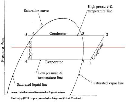
Figure 4 is a pressure-enthalpy diagram of a typical refrigeration cycle in a system with one pound of HFC-134a. It uses (for this example) evaporating and condensing temperatures of 0°F and 120°F. Points on the diagram are labeled to correspond to locations of equipment in the system. Each step of the cycle can be approached separately.

Refrigeration: Refrigeration Ph Chart
REFRIGERANTS P-H DIAGRAM - Refrigeration - The pressure-enthalpy diagram (log P/h diagram) is a very useful tool for refrigerant technicians, engineers and researchers. Since it's not always possible to have all of these diagrams together, we decided to give you this complete pack.

2018 Prudential Classic participants race down Putney High Street towards the end of the race
Learn how to properly set up a two point calibration for your pH sensor.The Model 56 advanced analyzer supports continuous measurement of analytical inputs from one or two sensors. The high resolution full-color display gives unsurpassed visibility and functionality for analytical instrumentation. The PERpH-X high performance...
Basic Refrigeration Cycle
In this video we explain the importance of the P-H diagram and how useful this is for the refrigeration cycle. Gauge and absolute pressure is also explained ...

Efficiency - Measuring Refrigeration
Document WO 2006/060253 of known art depicts a method and an apparatus using an organic Rankine cycle for generating energy on a sea boat. The method comprises the following steps: providing an ORC device including at least one evaporator, a turbogenerator, a condenser and a cooler feeding pump; arranging the evaporator within...
Entropy | Free Full-Text | Energetic and Exergetic ...
The following example is a simplified p-h diagram on which a refrigeration cycle is drawn. Point 1 to 4 show the following. Point 1 to 2: Refrigerant change in a compressor. Point 2 to 3: Refrigerant change in a condenser. Point 3 to 4: Refrigerant change through an expansion valve. Point 4 to 1: Refrigerant change in an evaporator.

Vapor-Compression Refrigeration Cycle (Interactive ...
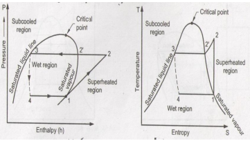
The log p-h diagram for refrigerant The refrigeration cycle For operating media which can have different phases, such as water or refrigerant, theT-sdiagram looks different. It has an area on the left (grey),in which the operating medium is liquid and supercooled. In the centre(blue) there is a mixture of steam and liquid, the wet steam.
34 Ph Diagram For Refrigeration Cycle - Wiring Diagram ...
The Best and Completed Full Edition of Diagram Database Website You Can Find in The Internet ... T One Wiring Diagram Webb Diagrams For Medical Surgical And Psych Mental Health Nursing The Best Way To Learn Material To Pass Nursing School Exams And The Nclex Mazda Miata 1993 Wiring Diagram Bf50d Wiring Diagram Stratus Fuse Diagram Explorer Radio Wiring Diagram A3 Hatchback Wiring Diagram Switch Wiring Diagram For 1980 Chevy Malibu Ford Taurus Spark Plug Wire Diagram Porsche 944 Electrical Wiring Diagram 485 4 Wire Connector Diagram 458 Workshop Wiring Diagram Rv Heater Wiring Diagram 9 3 Fo
Refrigeration: Refrigeration Ph Diagram
Vapour Compression Refrigeration Cycle. The P-H and T-S diagram for the simple vapor compression refrigeration cycle is shown in the figure for vapour entering the compressor is in dry saturation condition The dry and saturated vapour entering the compressor at point 1 that vapour compresses isentropic ally from point 1 to 2 which increases the pressure from evaporator pressure to condenser ...

Basic Refrigeration Cycle | Refrigeration and air ...
P-H Diagram for Ideal Conditions e . H 1 = h f based on temperature at 'd' (exit of condenser) H 2 = h g based on temperature at 'a' (exit of evaporator) Note 1: If there is super -heating in the evaporator, H 2 can not be obtained from P-H table Note 2: If there is sub- cooling in the condenser, H 1 can not be obtained from P-H table

City Bike Rentals
R22 P/H Diagram * Diagram created using REFPROP – NIST Reference Fluid Properties As can be seen, the critical point of R-22 is more than 200°F, placing it well above the operating conditions of typical refrigeration systems. This can be contrasted with the CO 2 PH diagram, with a critical point of 88°F.
34 Ph Diagram For Refrigeration Cycle - Free Wiring ...
Refrigeration handbook 1. Basic heat transfer 2. Compression cycle 2.1 The pressure-enthalpy diagram; 2.2 Basic components; 2.3 The basic cycle in a log Ph diagram; 2.4 The complex cycle in a log Ph diagram; 2.5 Other components; 3. Compressors 4. Expansion valves 5. Refrigerants 6. Evaporators 7. Condensers 8.

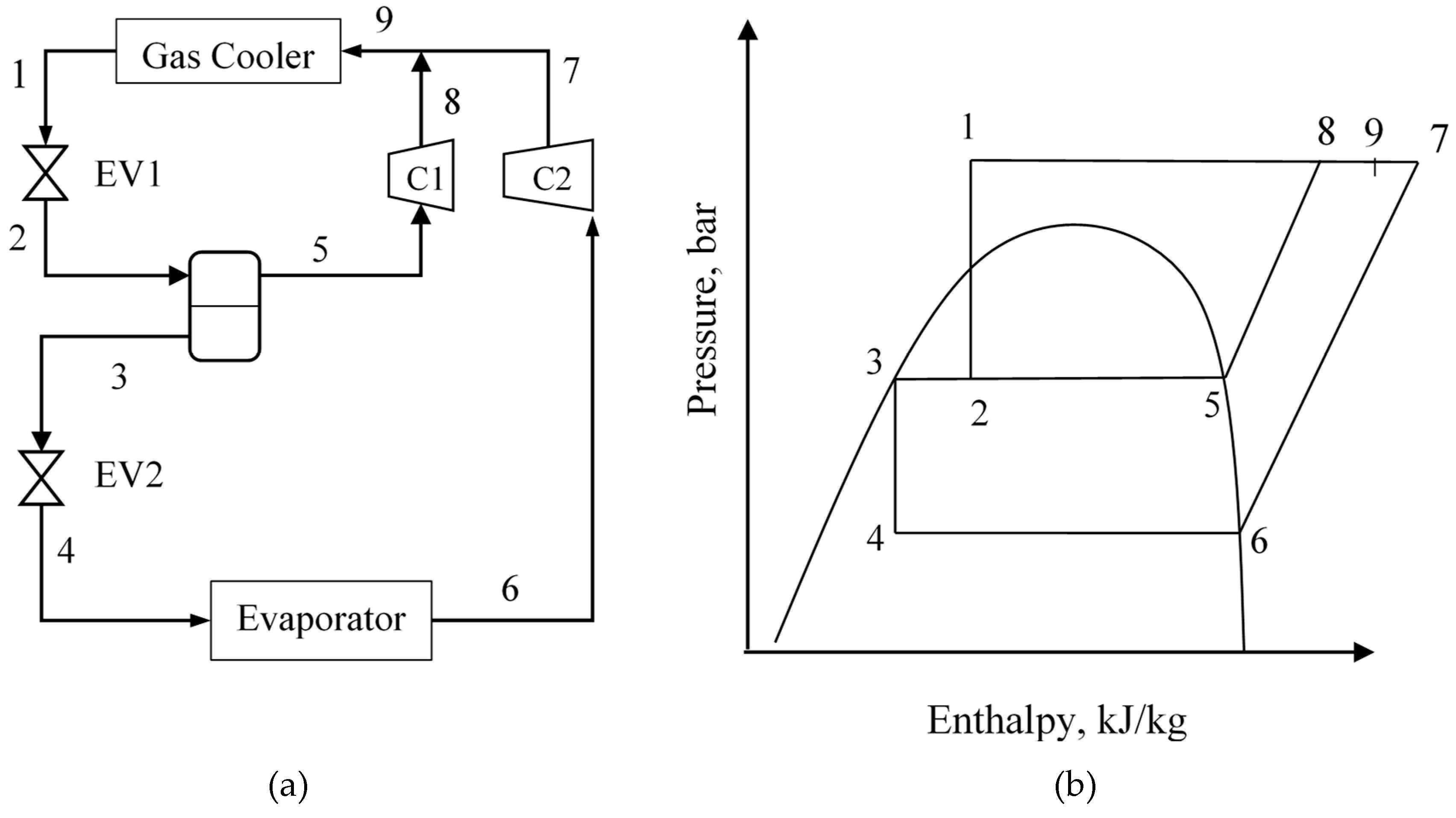
Schematic and P-h diagram of the conventional cascade ...
ElEctric Motors Control SyStemS Electric Motors and Control Systems, First Edition

That’s life
Sep 03, 2008 · Industrial refrigeration system design starts from P-H Diagram Refrigeration Cycle Analysis and Refrigerant Flow Diagram: (1) P-H Diagram Refrigeration Cycle Analysis. P-H Diagram is to analysis the feasibility of the refrigeration cycle, to calculate the thermodynamic properties of the refrigeration system. Use the P-H Diagram analysis, all the refrigerant flow rates and operating

17. Pressure-enthalpy chart for the heat pump cycle using ...
Figure 2-8: TS and P-H diagram for liquid sub-cooling in a refrigeration cycle. Exercise 2-4: Implement the sub-cooling cycle in Pro II and report the new COP. Compare it with the dry cycle without sub-cooling and the Carnot cycle. Use streams E and F as initial values. The flowsheet has two loops.
Refrigeration: P H Graph Refrigeration
Learn refrigerant flow in a vapor compression system using a schematic of various components and a pressure enthalpy diagram.

CO2 as a Refrigerant — Introduction to Transcritical ...
Refrigeration Cycle T-S & p-h Diagram The refrigerant cycle is described by the T-S & p-h diagram. Refrigeration cycle diagrams . COP of Refrigeration Cycle. The efficiency of the refrigeration cycle is described by COP or coefficient of performance. h1 = Sp. enthalpy before compression at Point 1;

Refrigeration Cycle Ts Diagram — UNTPIKAPPS
In general, a log p-h diagram shows the aggregate state of a substance, depending on pressure and heat. For refrigeration, the diagram is ...

e P-h diagram of refrigeration cycles with suction gas ...
The Best and Completed Full Edition of Diagram Database Website You Can Find in The Internet ... Electrical Circuit Diagrams Gmc Sonoma Wiring Diagram Diagram For 2001 Pontiac Aztek Celica Engine Diagram 1217 Civic Wiring Diagram Pigtail Wire Connector Wiring Diagram Wiring Rz 088 Dodge Ram Wiring Diagram Ford F350 Fuse Diagram Pool Pump Timer Wiring Diagram Cavalier Ignition Switch Wiring Diagram Wiring Diagrams Forester 2015 Wiring Diagram Transmission Review Ranger 4 0 Engine Exploded Diagram Door Inte Speaker Wiring Diagram Science And Engineering Chapter 11 Thermodynamic Databases And

vapour compression refrigeration cycle on p-h diagram ...
Fig. 11. T-S diagram for Wet Vapour Compression Cycle Fig. 12. P-h diagram for Wet Vapour Compression Cycle In this cycle, enthalpy at state 2 is found with the help of dryness fraction at this point (2). The dryness fraction at points 1 and 2 may be obtained by equating entropies at state 1 and 2. C.O.P = =

Refrigeration: Ph Diagram Refrigeration System
This paper is available online at http://journal.kepco.co.kr 299 Design of Thermodynamic Cycle and Cryogenic Turbo Expander for 2 kW Class Brayton Refrigerator 2 kW급 브레이튼 냉동기용 열역학 사이클 및 극저온 터보 팽창기 설계 Jinwoo Lee*, Changhyeong Lee*, Hyeongseok Yang**, Seokho Kim*† 이진우*, 이창형*, 양형석**, 김석호*† * Changwon National University, Changwon...

Ph Diagram For Refrigeration Cycle - General Wiring Diagram
Advanced Nuclear Power Technology Program A Supercritical Carbon Dioxide Cycle for Next Generation Nuclear Reactors V. Dostal, M.J. Driscoll, P. Hejzlar MIT-ANP-TR-100 March 10, 2004 i Acknowledgements Substantially the same document has been submitted by the principal author, Vaclav Dostal, as his thesis for the Doctor of...
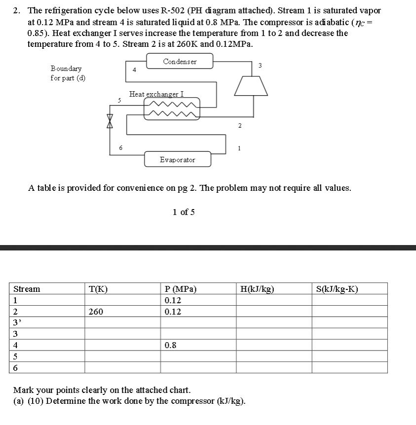
Solved: The Refrigeration Cycle Below Uses R-502 (PH Diagr ...
Figure 2.2 The log P/h Diagram with temperature lines. You are here: Home · Refrigerant handbook · 2. Compression cycle; 2.1 The pressure- ...

Schematic diagram of an ejector refrigeration cycle and ...
Figure 2.9 The real refrigerant cycle in the log P/h diagram. The overheating is the difference between the temperatures at points 1.1 and 1.2. The sub-cooling is the difference between the temperatures at points 3.1 and 3.2. Figure 2.10 Log P/h diagram with temperature levels shown. Figure 2.11 The energy flow in a refrigerant system.

The Refrigeration Cycle
http://docs.lib.purdue.edu/iracc/537 R3-1 THE APPLICATION OF VORTEX TUBES TO REFRIGERATION CYCLES *Gregory F. Nellis, Ph.D., Assistant Professor, University of... The potential for increasing the performance of a refrigeration cycle using the vortex tube is found to be extremely limited for the vapor compression cycle. However...
0 Response to "5 ph diagram for refrigeration cycle"
Post a Comment