38 shear moment diagram examples
A bending moment diagram is one which shows variation in bending moment along the length of the beam. Example 1 Draw the shear force and bending moment diagrams for the beam shown below a) determine the reactions at the supports. Taking moments about A (clockwise moments =anti-clockwise moments) 10 x2 = 5RC 5RC=20 RC=20/5 =4kN Resolving vertically
Problem 10: Bending Moment and Shear force A beam with a hinge is loaded as above. Draw the shear force and bending moment diagram. Solution: Concept: A hinge can transfer axial force and shear force but not bending moment. So, bending moment at the hinge location is zero. Also, without the hinge, the system is statically indeterminate (to a ...
4.0 Building Shear and Moment Diagrams. In the last section we worked out how to evaluate the internal shear force and bending moment at a discrete location using imaginary cuts. But to draw a shear force and bending moment diagram, we need to know how these values change across the structure.

Shear moment diagram examples
Dr. M.E. Haque, P.E. Beam Reactions, Shear and Moment (Page 7 of 12) w L Sym. 2 / 8 - w x2 /2 w x2 /2 P 1 L / 4 P 2 x w L / 2 + P 1 / 2 MOMENT DIAGRAMS Fig. 1 Fig. 2 Fig. 3 Algebraic summation of coordinates of these three moment diagrams will produce the final moment diagram.
Example 2. Simply supported beam calculation. Calculate the support reactions. Draw the Bending Moment diagram. Draw the Shear Force Diagram. Draw the Axial Force Diagram. More. Example 3. Cantilever beam calculation carrying a uniformly distributed load and a concentrated load.
Example Problem Shear and Moment Diagrams Calculate and draw the shear force and bending moment equations for the given structure. 11 Sketching the Deflected Shape of a Beam or Frame Qualitative Deflected Shape
Shear moment diagram examples.
and integrating the shear diagram to get the bending moment (adding jumps at all point couples). The following is an example of one shear load and bending moment diagram. Note: 1. room under it for the shear and moment diagrams (if needed, solve for support reactions first). 2. Draw the shear diagram under the free-body-diagram.
this is a detailed example of shear and moment diagrams, i recommend skipping around to the sections shown below if you already have a feel for the subject:i...
Amount of shear = slope of the moment diagram Where the shear diagram crosses the axis is a max or min on the moment diagram Drawing shear and moment diagrams process: Establish your coordinate system with the positive X direction being along the length of the beam, starting on the left.
Shear Moment Diagram Examples. chapter 2 shear force and bending moment draw the shear force and bending moment diagrams shear force & bending moment example 1 draw the free body diagram by taking the moment at b shear and moment diagrams shear and moment diagrams consider a simple beam shown of length l that carries a uniform load of w n m throughout its length and is held in equilibrium
Examples: Level 1: Single Point Load. This is example shows how to use the steps outlined in the "Steps" tab to draw shear force and bending moment diagrams. Level 2: Distributed Force. This example deals with a constant distributed force (shear is a linear function of x). Level 3: Point Moment. In this example, the point moment causes no shear ...
Example: Draw the shear and moment diagrams for the following beam using superposition: + = + CIVL 3121 Shear Force and Bending Moment Diagrams for Frames 4/5. Shear and Moment Diagrams by Superposition Example: Draw the shear and moment diagrams for the following beam using superposition. 10 ft. A 4 k/ft.
Shear and Moment Diagrams Shear and Moment Diagrams Consider a simple beam shown of length L that carries a uniform load of w (N/m) throughout its length and is held in equilibrium by reactions R 1 and R 2. Assume that the beam is cut at point C a distance of x from he left support and the portion of the beam to the right of C be removed.
Being able to draw shear force diagrams (SFD) and bending moment diagrams (BMD) is a critical skill for any student studying statics, mechanics of materials, or structural engineering. ... Shear force and bending moment diagram example #1: single point load; Shear force and bending moment diagram example #2: multiple point loads ...
Basic Example to Construct a Shear and Moment Diagram : Constructing shear and moment diagrams is similar to finding the shear and moment at a particular point on a beam structure. However, instead of using an exact location, the location is a variable distance 'x'. This allows the shear and moment to be a function of the distance, x.
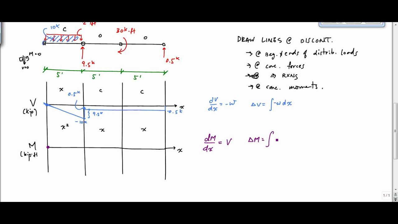
The equation also suggests that the slope of the moment diagram at a particular point is equal to the shear force at that same point. Equation 6.1 suggests the following expression: ΔM = ∫ V (x)dx Δ M = ∫ V ( x) d x (Equation 6.2) Equation 6.2 states that the change in moment equals the area under the shear diagram.
3.2 - Shear Force & Bending Moment Diagrams What if we sectioned the beam and exposed internal forces and moments. This exposes the internal Normal Force Shear Force Bending Moment ! What if we performed many section at ifferent values Of x, we will be able to plot the internal forces and bending moments, N(x), V(x), M(x) as a function Of position!
Shear and Moment Diagrams. As an alternative to splitting a body in half and performing an equilibrium analysis to find the internal forces and moments, we can also use graphical approaches to plot out these internal forces and moments over the length of the body. Where equilibrium analysis is the most straightforward approach to finding the internal forces and moments at one cross section ...
Shear and moment diagram... - civil engineering discoveries ...
4.4 Area Method for Drawing Shear- Moment Diagrams Useful relationships between the loading, shear force, and bending moment can be derived from the equilibrium equations. These relationships enable us to plot the shear force diagram directly from the load diagram, and then construct the bending moment diagram from the shear force diagram.
The ultimate guide to shear and moment diagrams ...
Shear and moment diagrams and formulas are excerpted from the Western Woods Use Book, 4th edition, and are provided herein as a courtesy of Western Wood Products Association. Introduction Notations Relative to "Shear and Moment Diagrams" E = modulus of elasticity, psi I = moment of inertia, in.4 L = span length of the bending member, ft.

Drawing shear and moment diagrams for beam
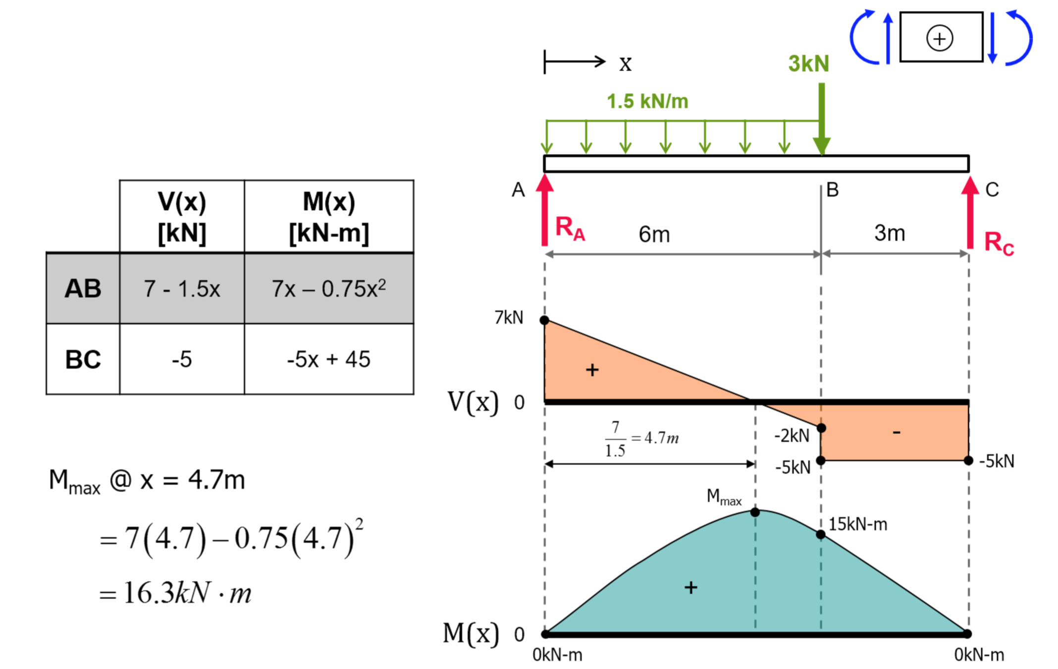
Calculate the shear force and bending moment for the beam subjected to a concentrated load, then draw the shear force diagram (SFD) and bending moment diagram (BMD). Answer: By taking the moment at A, MA = 0 - RBy × 5 + 15 × 3 = 0 RBy = 9 kN Fy = 0 RAy + RBy = 15 RAy = 15 - 9 RAy = 6 kN Fx = 0 , RAx = 0 Shear force and bending moment diagram
Mechanics of materials chapter 4 shear and moment in beams
Lesson 12: Drawing Shear and Moment Diagrams Example- Mechanics of Materials and Statics. This is a detailed example of shear and moment diagrams.
Shear force and bending moment diagrams graphical method ...
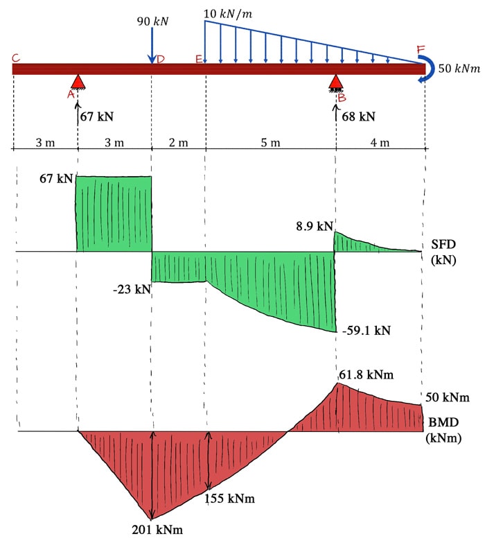
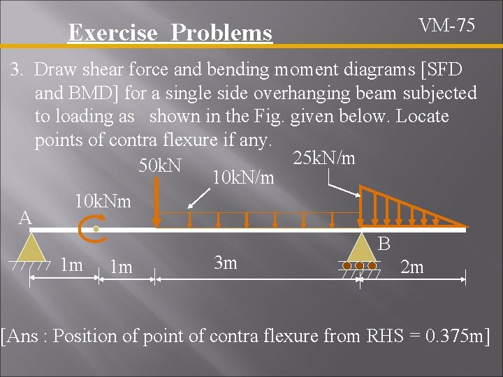
PDF_C8_b (Shear Forces and Bending Moments in Beams) Q6: A simply supported beam with a triangularly distributed downward load is shown in Fig. Calculate reaction; draw shear force diagram; find location of V=0; calculate maximum moment, and draw the moment diagram. 6k/ft 9 ft RA = (27k)(9-6)/9= 9k A B F = (0.5x6x9) = 27k x = (2/3)(9) = 6 ft

Cantilever beam: shear force and bending moment diagram practice problem | facebook
CE 331, Fall 2007 Shear & Moment Diagrams Examples 3 / 7 max MD = 16.0k-ft at Support 2 3. Calculate the max. moment due to live load (ML) at the location of the max. moment due to dead load (MD). 3.1 Determine where to place the live load to cause the max ML at the middle of Span 1. As mentioned on Page 1, the location of live loads is variable.
Solved draw the shear force diagrams and the bending moment ...
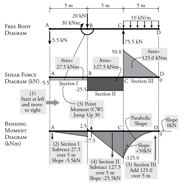
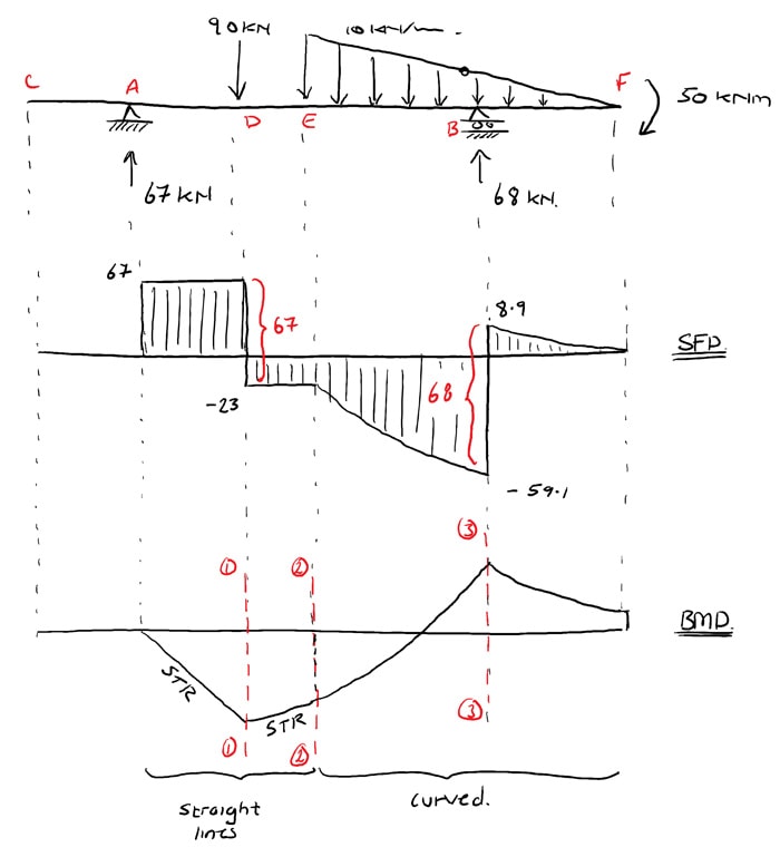
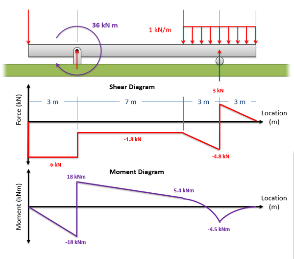
In segment CD, the shear is uniformly distributed at a magnitude of -24 kN. To draw the Moment Diagram: The equation MAB= -30x is linear, at x = 0, MAB= 0 and at x = 1 m, MAB= -30 kN·m. MBC= 26x - 56 is also linear. At x = 1 m, MBC= -30 kN·m; at x = 4 m, MBC= 48 kN·m. When MBC= 0, x = 2.154 m, thus the moment is zero at 1.154 m from B.

Statics ebook: shear, moment and load relations
A shear-moment diagram is an engineering tool where the shear force is calculated at each point along the length of he beam. A moment diagram is drawn below the shear diagram to the same scale. The moment can be calculated at any point by integrating the shear diagram.

Ultimate guide to shear force and bending moment diagrams ...
Shear and Moment Diagrams - Including the 3 Moment Equation and Examples - Free ebook download as Word Doc (.doc / .docx), PDF File (.pdf), Text File (.txt) or read book online for free.

Shear force and bending moment diagrams. | download ...
2 LECTURE 13. BEAMS: SHEAR AND MOMENT DIAGRAMS (GRAPHICAL) (5.3) Slide No. 2 ENES 220 ©Assakkaf Example 8 (cont'd) A free-body diagram for the beam is shown Fig. 17. The reactions shown on the

1. draw a shear force and bending moment diagram for the beam ...
Example of drawing a shear and moment diagram graphically for a simply supported beam with a concentrated moment and linearly distributed load. I recommend ...

Statics ebook: shear, moment and load relations
Solution to problem 403 | shear and moment diagrams ...

Moment diagrams constructed by the method of superposition ...

Shear force and bending moment diagram practice problem #1
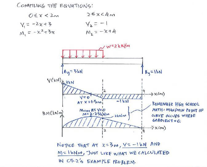
Example - equation approach | c5.3 shear force and bending ...

Shear and moment diagram - wikipedia

Shear-force and bending-moment diagrams along the base of the ...

Bending moment diagram - an overview | sciencedirect topics

Draw the shear and moment diagrams for the beam. | study.com

Learn how to draw shear force and bending moment diagrams ...
Shear load and bending moment diagrams
Unit 6: bending\. shear and moment diagrams - online presentation
Definition of shear and moment diagrams | chegg.com
Moment diagrams: examples

Shear moment diagram example

How to plot bending moment diagram from shear force diagram ...
Shear force and bending moment diagrams sfd bmd
Exercise: shear force & bending moment diagrams (solution ...

Drawing bending moment diagrams effectively - mechanicalbase
De-12: lesson 19. solved examples based on shear force and ...
Mechanics of materials chapter 4 shear and moment in beams

Structure analysis i. lecture 8 internal loading developed in ...

Brief information about shear force and bending moment ...
The ultimate guide to shear and moment diagrams ...
6.2 shear/moment diagrams – engineering mechanics: statics
Shear and moment diagram example 3 - mechanics of materials
0 Response to "38 shear moment diagram examples"
Post a Comment