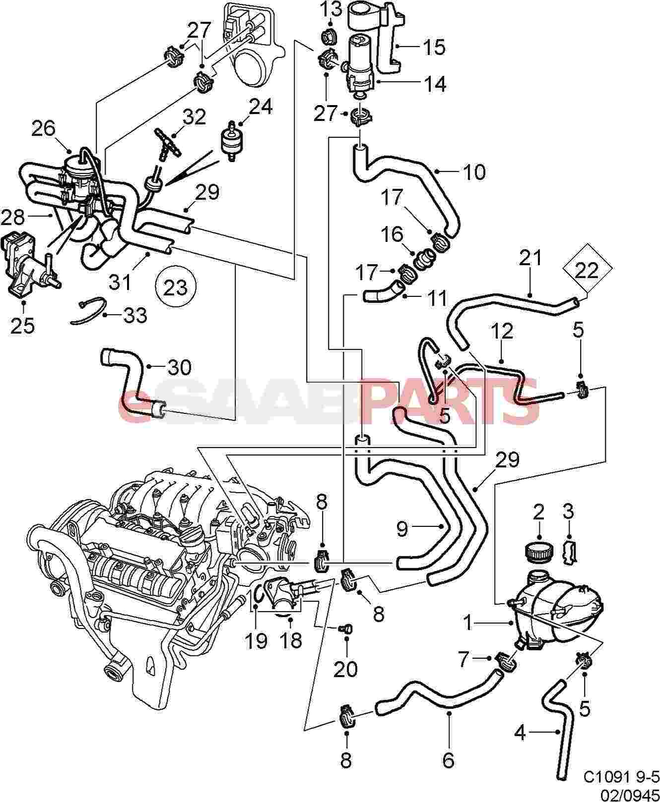
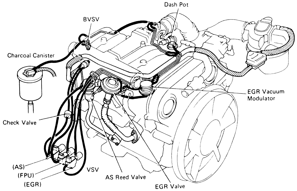
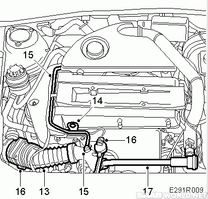
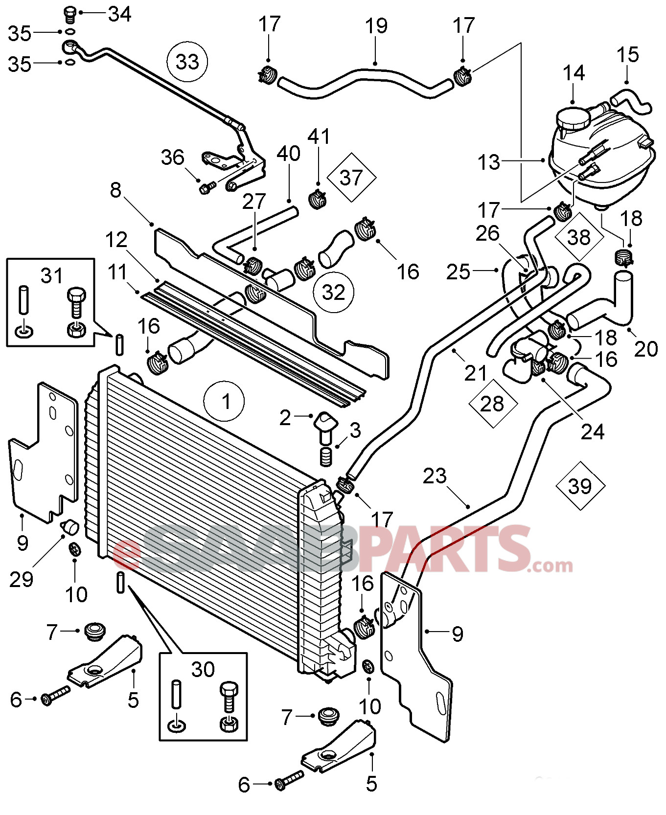
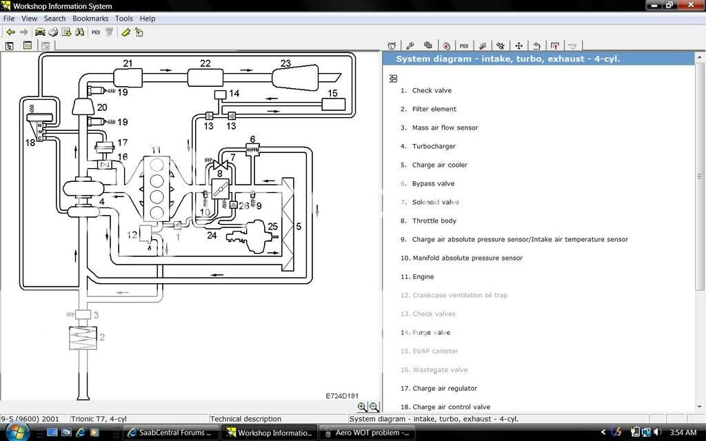
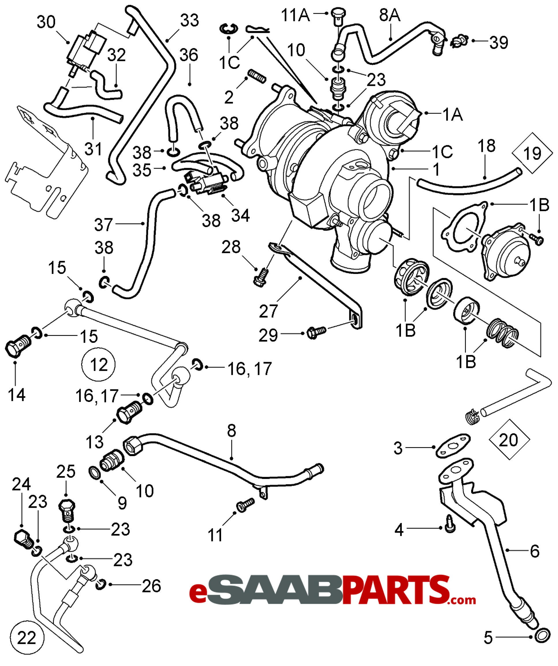
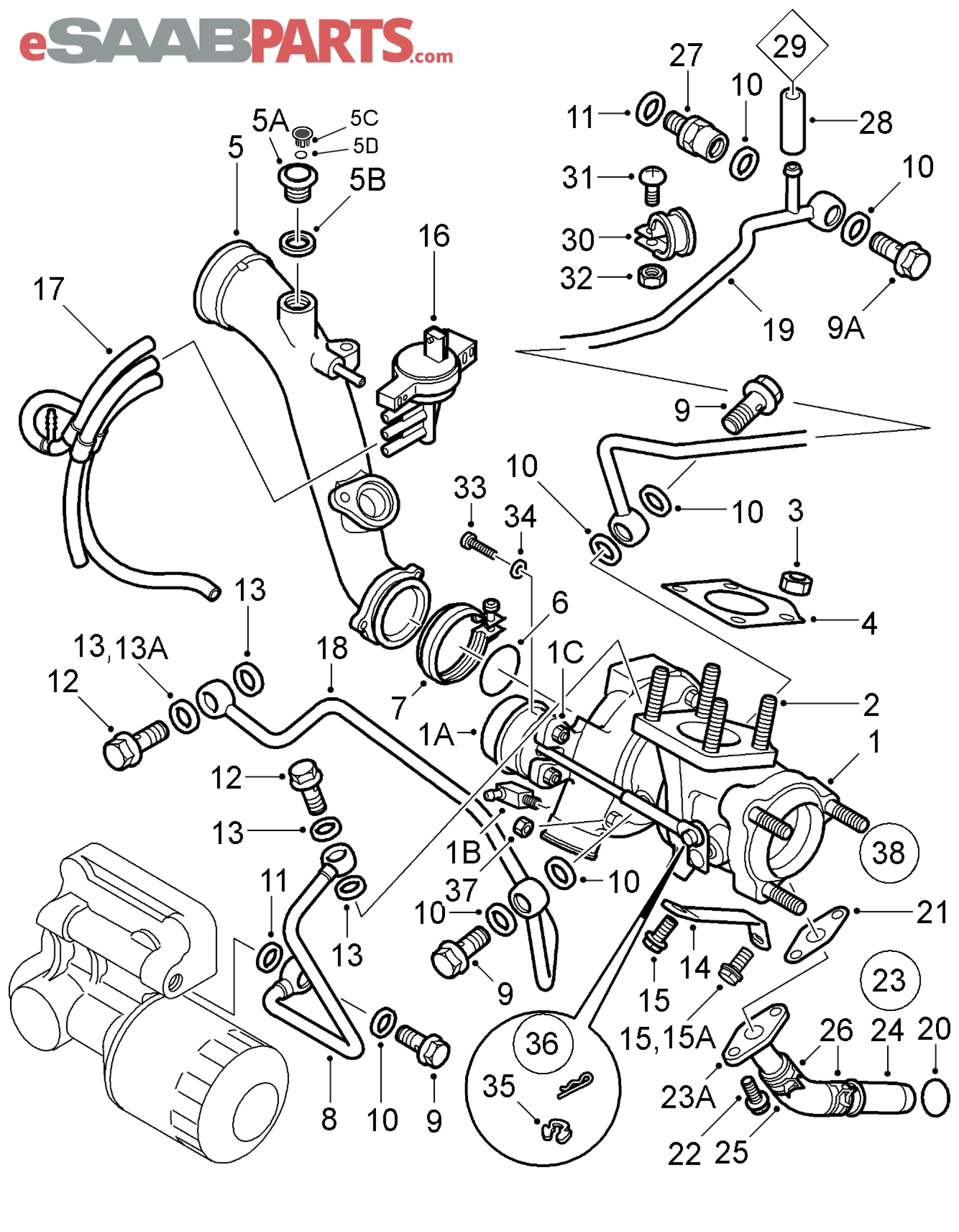
37 2004 9-5 arc vacuum hose layout diagram
Vaccuum hose diagrams I am in need of a vaccuum hose layout/diagram for a 1978 toyota corolla with a 2tc engine 1588cc, non-california car. vaccuum hose is connected to manifold however no suction to brake booster 2005 ford f150 Need vacuum line diagram for 2005 ford f150 or need to... any link to vacuum hose layout. If you are looking for a "vacuum diagram" like usually given for more regular engines using throttle plate for intake air control, I don't know if there is one for...
i have a 93 toyota 4 runner in need to a diagram of the vacuum hoses and a fuel return line on a 3.0 V6 the hose are all on the right side of the engine Can you please provide me with diagram of the layout of a timing belt and also position of timing marks for a harrier. Also I needed wiring diagram for...
2004 9-5 arc vacuum hose layout diagram
I am looking for a vacuum hose diagram for my 2004 X3 3.0i. I found the component layouts no problem on RealOEM, but need the actual vacuum hose... current-voltage characteristics of a vacuum arc discharge with plasma-forming gases of helium. and argon are considered. In this review we analyze the current state of experiments and theory relating to the cathode spot of a vacuum arc. We discuss technical features of the experimental study of the... Hi, please i will be grateful if someone can furnished me with Mazda 6,2004 make, vacuum hoses layout illustration, and also part catalog searchable by VIN, please i will consider USA catalog grateful. Need engine wiring diagram land rover td5 2004.
2004 9-5 arc vacuum hose layout diagram. A few questions regarding the Evap Solenoid and Vacuum Hose layout. - What does the Evap Solenoid look like? - Does anyone have a picture of their engine that points out where exactly all the vacuum hoses and lines go? I know there's a diagram under the hood, but it's pretty useless to me... Turns out the dealer had something more in mind. He recommended that I get an "updated" new PCV valve and hose. The PCV stuff is partly visible under the engine plastic cover around the oil filler cap and valve cover with hoses going behind the engine to the back of the block where there is a plastic... And turns out I don't have a catch can I guess. So I was looking at diagrams for engines that had a catch can so when I finally learned that I felt really dumb. Has anyone come up with a more aesthetic system of running vacuum hoses and wiring on top of the engine? Vacuum arc plasma discharges are intense sources of dense metal plasma, and can be used to deposit metal alloy thin films of various kind including both conventional alloys as well as non-equilibrium alloys. In our approach, the basic plasma deposition process is combined with the ion...
Does anyone have a vacuum diagram for this machine or can confirm where those three hoses go? Additionally, I can tell that the converter/regulator was recently replaced as it looks considerable newer that the other components. The regulator is a Impco J (P/N JB) can anyone confirm that is the correct... Toyota numbered the vacuum hoses and it looks like yours are still numbered correctly from your pictures. I list the Toyota vacuum hose numbers as printed on the the hose itself as well as where it goes. Read Or Download Escape Vacuum Hose Diagram For FREE Hose Diagram at BEEFDIAGRAM.PARCODELLEGITE.IT. Repair Guides. 2004 Ford Escape Vacuum Hose Diagram. Vacuum Hose Diagram. Jump to Latest Follow. If anyone else has access to this diagram, can they verify this? I had a hard time making out some of the lettering. Not sure if your interested, but some emission hose layout of Austalian spec. 4A-C motor, listed Dicipleofthelie · updated Jan 24, 2004.
Read Or Download Escape Vacuum Hose Diagram For FREE Hose Diagram at DIAGRAMTHEFALL.ALBERGOTREPOZZI.IT. Repair Guides. 2004 Ford Escape Vacuum Hose Diagram. Anti-theft Wiring Diagram for Saab 9-5 Arc 2004. Body control modules. TWICE Control Module Wiring Diagram for Saab 9-5 Arc 2004. Computer data lines. Vacuum arc-melting is also used for processing high temperature alloys; for jet engines, high purity materials Figure 3.4: Schematic diagram of the three main types of vacuum arc melting furnace, (a) consumable electrode Figure 4.3 shows a schematic of the pumps layout with the pneumatic valves. Unkie Scott and I work on Little Jake's 1998 Ford F-150. It was dying at idle. If he let off the throttle on the road, the truck died, he lost power...
Vacuum Hose Diagram I Need A Vacum Hose Diagram For A. layout planning Timing diagram: digital timing diagram Timing diagram: UML 2.0 TQM diagram Treemap UML diagram - Unified Modeling Language (used in software engineering) Use case diagram - from UML 5/9 and SysML...
Visual Paradigm provides a layout facility for arranging diagram elements in diagrams. This page will introduce different layout styles and configurable options. Diagram elements do not overlap and the relationship links do not cross over one another.
Search inside document. Vacuum system, hose layout. Documents Similar To 87-184 Vacuum System Hose Layout. Carousel Previous Carousel Next.
The diagram show both reservoirs connected to each other and then it goes to the main line that feeds from the intake manifold on the The T hose connector broke and the white connector on the reservoir too, so I assume a small hose is missing.
vacuum hose layout. Jump to Latest Follow. 1. You need 2 check valves. Look at the diagram 2. One hose goes to the brake booster with a check valve; the other goes to the heater control valve. #5 · Jul 8, 2004. Buy the barbs from McMaster Carr (on the web...but trust me when I say this ***order by...
I have a 95rex and i know the Vacuum hoses are incorrectly fitted and my car just isnt PLEASE it runs like a dog. [Edited by 95wrxwhite - 1/16/2004 12:05:59 AM]. I know this is an old thread but is the vacuum hose layout the same on a p1?
3. CATHODE-SPOT VACUUM ARC <ul><li>CATHODE-SPOT VACUUM ARC is a high current , low voltage electrical discharge, sustained between two electrodes - cathode and anode, in which a conducting medium is a highly ionized plasma , generated from luminous regions moving throughout...
KLDE/KL-DE/KL03 Vacuum Hose Diagrams for Mazda 626, Mx6, and ford Probe. Diagram 1: Color Coded. There should only be one hose that needs to be connected, that hose connects to the valve cover. Check out this photo at my old website
Vacuum hose layout. Jump to Latest Follow. As far as I can make out. The vacuum hoses are connected correctly as per original Nissan design. You wouldn't be getting any boost at all if the VNT actuator was connected to the intake air control vacuum hose.
Vacuum Line Diagram 2004 Ford I need a vacuum diagram of 2004 5.4 ford expedition there is a valve mounted on firewall which has two vacuum lines going into it and it controls heat and AC controls vent, floor, vent and floor and d … read more.
can anybody link me to a Vacuum Hose layout or diagram for my BMW 328i or similar E36's? thx, o¿O. Vacuum hose diagram? Jump to Latest Follow.
Read Or Download Tdi Vacuum Diagram For FREE Vacuum Diagram at DIAGRAMRT.AITREARCHIVENEZIA.IT. Vacum Line Layout Help 110 Ahf. Vnt Turbo And Performance Mods - 300 Tdi. B5 Vacuum Hose Diagram. Please Help Another 2000 Audi A4 B5 1 9...
Hi, please i will be grateful if someone can furnished me with Mazda 6,2004 make, vacuum hoses layout illustration, and also part catalog searchable by VIN, please i will consider USA catalog grateful. Need engine wiring diagram land rover td5 2004.
current-voltage characteristics of a vacuum arc discharge with plasma-forming gases of helium. and argon are considered. In this review we analyze the current state of experiments and theory relating to the cathode spot of a vacuum arc. We discuss technical features of the experimental study of the...
I am looking for a vacuum hose diagram for my 2004 X3 3.0i. I found the component layouts no problem on RealOEM, but need the actual vacuum hose...

![[EM_7333] Saab Vacuum Line Diagram Download Diagram](https://static-assets.imageservice.cloud/1364542/saab-vacuum-diagram-wiring-diagram-data.jpg)
![[55560445] SAAB PCV Breather Hose - Lower (PCV Box to Oil ...](https://www.esaabparts.com/static/images/diagrams/98601.jpg)







0 Response to "37 2004 9-5 arc vacuum hose layout diagram"
Post a Comment